José M. ´Alvarez, Ferran Diego, Antonio López, Joan Serrat, Daniel Ponsa. Computer Vision ..... [1] José M. ´Alvarez, Antonio M. López, and Ramon Baldrich,.
AUTOMATIC GROUND–TRUTHING USING VIDEO REGISTRATION FOR ON–BOARD DETECTION ALGORITHMS ´ Jos´e M. Alvarez, Ferran Diego, Antonio L´opez, Joan Serrat, Daniel Ponsa Computer Vision Center and Computer Science Dpt. Autonomous University of Barcelona ABSTRACT Ground–truth data is essential for the objective evaluation of object detection methods in computer vision. Many works claim their method is robust but they support it with experiments which are not quantitatively assessed with regard some ground–truth. This is one of the main obstacles to properly evaluate and compare such methods. One of the main reasons is that creating an extensive and representative ground– truth is very time consuming, specially in the case of video sequences, where thousands of frames have to be labelled. Could such a ground–truth be generated, at least in part, automatically ? Though it may seem a contradictory question, we show that this is possible for the case of video sequences recorded from a moving vehicle. The key idea is to manually label the frames in one sequence and then be able to transfer this segmentation into another video sequence recorded at a different time on the same track, possibly under a different ambient lighting. We have carried out experiments on several video sequence pairs and quantitatively assessed the precision of the transformed ground–truth, which prove that this method is quite accurate. Index Terms— Ground–truth generation, video registration. 1. INTRODUCTION On–board detection algorithms refers to those methods that uses images acquired with a camera mounted in a mobile platform (i.e., vehicle) as input data. The detection process consists in classifying pixels in the image as target (road, vehicles, pedestrians) or background. The objective evaluation of on–board detection algorithms is usually done by comparing the result with an ideal result (or ground–truth) which is mainly generated manually. The manual annotation over all the data collection is expensive and very time consuming, specially in the case of video sequences, where thousands of frames have to be labelled. This effort is even higher for those algorithms which This work was supported by the Spanish Ministry of Education and Science under project TRA2007-62526/AUT and research programme Consolider Ingenio 2010: MIPRCV (CSD2007-00018).
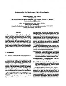
Fig. 1. The evaluation on–board detection algorithms which are claimed to be robust to lighting variations requires imaging and ground–truthing the same scene under different illumination conditions. are claimed to be robust to imaging conditions (i.e., varying illumination and weather conditions [1]). Their evaluation involves imaging and ground–truthing the same scene acquired under different conditions (Fig. 1). Annotating such large volumes of ground–truth data involve having errors due to the drop off of the user attention. Hence, any degree of automation within this process leads to a more accurate ground–truth data since it requires less time and the user can maintain the attention. There are only a few approaches addressing the problem of automatic ground–truth generation. However, these works refers to static cameras [2] or aerial images [3]. The former can not be applied to moving cameras and the latter presents a method for generating the ground–truth of the frames in a video sequence assuming the ground–truth of some key frames exists. However, this can not be applied to generate the ground–truth of a video sequence given the ground–truth of another sequence. In this paper, as a novelty, an automatic ground–truthing algorithm is proposed. In particular, we focus on the generation of ground–truth data of video sequences recorded using moving cameras. The key idea of the algorithm is to manually label the frames in one sequence and then be able to transfer this segmentation into another video sequence recorded at a different time on the same track, possibly under different illumination. To this end, we first solve the problem of temporal alignment (synchronization) of the two videos, since the vehicle speed varies along time and between videos. Once it is done, corresponding frames can be spatially registered, and then, the ground-truth region from annotated video can
be transferred to the target one. The rest of this paper is organized as follows: First, in Sect. 2, the automatic ground–truthing algorithm is introduced. Experiments to validate the algorithm are presented in Sect. 3. The goal of the experiments is to generate the ground–truth to evaluate road detection algorithms under varying illumination conditions. Quantitative and qualitative evaluation are provided. Finally, in Sect. 4 conclusions are drawn. 2. AUTOMATIC GROUND–TRUTHING ALGORITHM In this section the automatic ground–truthing algorithm is introduced. The aim of the algorithm is the generation of ground–truth data of video sequences recorded using moving cameras. The key idea of the devised algorithm is transferring the known ground–truth of one video sequence into another video sequence recorded at different time and different lighting conditions but under the same track. The algorithm, which considers the knowledge of a reference sequence and the ground-truth for each image of the reference video, is divided in two major phases (Fig. 2). In the first phase, the temporal alignment (synchronization) between the input video sequence and the reference is solved. Then, in the second phase, corresponding frames are spatially registered. The result is used to transfer the ground–truth of from one sequence to the other.
ments of our application. This technique is divided in two different parts: temporal alignment and spatial registration. 2.1.1. Temporal Alignment Temporal alignment can formulated as a labeling problem which consists in estimating a list of no labels x1:no = [x1 . . . xt . . . xno ]. Each label xt is the frame number in the reference video corresponding to the t th frame of the observed sequence. This task has been posed as a maximum a posteriori Markov random field inference problem following: xMAP 1:no
= arg min U (x1:no |y1:no ) x1:no ∈X
∝
arg min U (y1:no |x1:no ) + U (x1:no ) x1:no ∈X
where X is the set of all possible labellings, U (x1:no ) is the prior energy and U (y1:no |x1:no ) is the likelihood energy. Hence, Viterbi algorithm [9] is applied to exactly infer xMAP 1:no The prior energy is expressed as a pairwise energy term written as no −1
∑ V (xt , xt+1 )
U (x1:no ) =
(2)
t=1
where V (xt , xt+1 ) is the potential clique used to constraint the vehicle movement whose can stop but not reverse its motion direction in both sequences. Therefore, the labels xt must increase monotonically following ½ V (xt , xt+1 ) =
Fig. 2. Automatic ground–truthing algorithm.
(1)
β 0
if xt+1 ≥ xt otherwise
(3)
where β is a constraint that gives the same importance to any label greater or equal than xt . The likelihood energy U (y1:no |x1:no ) is the unary term of our MRF expressed by
2.1. Video Registration The aim of video registration is to find out a mapping from the time domain of one sequence to another one, such that corresponding frame pairs, one from each sequence, show ’similar content’ [4]. This is a challenging task since the images are taken at different time from a mobile platform manually operated. Hence, the platform does not follow exactly the same trajectory and does not maintain a constant speed. Ground–truth generation for on–board detection algorithms has three main requirements: (1) independent movements of the cameras (mobile platforms), (2) unknown platform trajectories and (3) non–linear time correspondences due to non–constant speeds. Although many video registration techniques have been proposed [5, 6, 7, 8], only the technique proposed in [8] can deal with the specific require-
no
U (y1:no |x1:no ) =
∑ V (xt , yt )
(4)
t=1
where V (xt , yt ) is the frame similarity which must be minimum if two frames are corresponding. Additionally, this must satisfy the assumption that both videos were recorded following similar trajectories. An image descriptor is defined, d, in order to compare a pair of images. To compute d the following steps are done: first, the original image is smoothed a Gaussian kernel and downsampled to 1/16th of the original resolution. Then, the partial derivatives (ix , iy ) are computed setting them to zero if its gradient magnitude is less than 5% of the maximum. The rows of ix followed by those of iy are built as a vector d∗ which
is normalized to unit norm. Finally, the frame similarity is defined as,
V (xt , yt ) =
(< dt , dxt > −1)2 2σa2
(5)
where dt is the image descriptor of the t th frame of observed sequence, dxt is the image descriptor of the xtth frame of reference sequence, σa has been to set to 0.5 to give a significant likelihood only to frames whose image descriptor form an angle less than 5o degrees approximately, and is the scalar product which can be considered as the coincidence of the gradient orientation in the subsampled image. In addition, this likelihood must be also low when appears slight camera rotations and translations due to trajectory dissimilarities. dt is computed from horizontal and vertical translations of the low resolution smoothed image up to 2 pixels. Then, the frame similarity is the maximum value obtained using the scalar product dt . 2.1.2. Spatial Registration The result of the temporal alignment is a list of pairs of corresponding frame numbers (t, xt ),t = 1 . . . no . Ideally, for each pair of frames the camera was at the same position or very close to each other. In that case, only the camera pose may be different. Let the rotation matrix R express the relative orientation of the camera for one pair of frames. The coordinates of the two corresponding frames Fto , Frxt are related by the homography H = KRK −1 , where K = diag( f , f , 1), f being the camera focal length in pixels. The rotation R is parameterized by the Euler angles Ω = (Ωx , Ωy , Ωz ) (pitch, yaw and roll respectively). The motion vector field associated to this homography can be approximated using the model in [10]. This model holds under the assumption of having small angles and large focal length. The model is quadratic in the x and y coordinates but linear in the parameters Ω: " u(x; Ω) =
− xyf 2
− f − yf
2
f + xf
xy f
# Ωx Ωy . x Ωz
−y
Ω
¡
∑ x
£ r ¤2 ¢ Fxt (W (x; Ω)) − Fto (x)
In this section the proposed algorithm has been used to generate the ground–truth data for on–board road detection algorithms [1]. The aim of these algorithms is to detect the road in front of a moving vehicle using a single color camera attached to the windshield, forward facing. One of the major challenges of these algorithms is dealing with lighting variations (i.e., shadows, highlights). Thus, the algorithm has to be tested using video sequences with hundreds of frames of the same track acquired under different conditions (Fig. 1). The experiments have been conducted on two different video sequences on the same track. The former sequence contains 627 frames and was recorded in the morning. That is, without shadows. The latter contains 540 frames and was recorded under the influence of lighting variations. The difference in the number of frames is due to differences in the trajectory and speed of the vehicle. Both sequences were recorded at the same frame rate. Ground–truth data of each frame in one sequence (the reference) has been manually generated. Example results of the generated ground–truth for the second sequence are shown in Fig. 3 and Fig. 4. These results suggest that the reference ground–truth is correctly transferred from the reference sequence to the input one. As shown, errors are mainly concentrated on boundaries Fig. 3c. However, these errors may be due to the boundary ambiguity error. This error refers to the inherent ambiguity in the boundary perception when manually segmenting the images to generate the ground–truth.
(a)
(b)
(c)
(d)
(6)
Ω parameters are estimated by minimizing a registration error. In particular, the sum of squared linearized differences (i.e., the linearized brightness constancy) is used: Ω∗ = argmin
3. RESULTS
(7)
In order to deal with large miss–alignments, Ω parameters are successively estimated in a coarse–to–fine manner. For a detailed description we refer the reader to [11].
Fig. 3. Example results. The frame from the reference sequence (a) is aligned with the input frame (b). The reference ground–truth (c) is used to generate the output ground–truth. Yellow color refers to true positive pixels. Black color refers to true negative pixels. Red color refers to false positives while green colors refers to false negatives. Quantitative assessment is provided using two pixel–wise
(a)
minor limitation since vehicle detection algorithms can be included in the registration process. Once the car is detected the ground truth can be covered. In addition, this algorithm can be used in semi–supervised operation. That is, the ground– truth is automatically generated and shown to the operator for validation. Even this would not be completely automatic, the amount of time saved is still considerably.
(b)
4. CONCLUSIONS
(c)
(d)
Fig. 4. Example results. See Fig. 3 for details. T P+T N error measures: accuracy (ACC = T P+FP+FN+T N ) and qualTP ity (gˆ = T P+FP+FN ). TP is the number of correctly labelled road pixels, TN is the number of non-road pixels detected, FP is the number of non-road pixels classified as road pixels and FN is the number of road pixels erroneously marked as nonroad. Each of these measures provides different insight of the results. Accuracy provides information about the fraction of classifications that are correct. Quality provides information about the completeness of the extracted data as well as its correctness. Both measures range from 0 to 1, where 1 corresponds to the ideal result. To properly assess the quality of the results, manual ground–truth has been generated for the input sequence. Having both manual ground–truth available, two different evaluations have been done. The former uses the first sequence as reference. The latter uses the second as reference. The averaged performance over all the corresponding frames is shown in Table. 1. Small differences are due to the different number of frames in each video sequence. The highest performance is achieved when the largest video sequence is used as reference. The main reason is that the algorithm does not interpolate the information between frames. Thus, the large amount information available as reference, the highest accuracy in the registration process. However, this is a minor drawback since reference sequence can be recorded driving at a lower speed or recording at a higher frame–rate.
Using seq. 1 as reference Using seq. 2 as reference
gˆ
ACC
0.98 ± 0.02
0.67 ± 0.15
0.97 ± 0.001
0.67 ± 0.15
Table 1. Performance of the ground–truthing algorithm. An inherent limitation of the method is the presence of moving vehicles in the input sequence. However, this is a
In this paper, as a novelty, an automatic ground–truthing algorithm has been proposed. The key idea of the algorithm is to manually label the frames in one sequence and then be able to transfer this segmentation into another video sequence recorded at a different time on the same track, possibly under different illumination. The algorithm has been successfully applied to generate the ground–truth necessary to assess on– board road detection algorithms. Qualitatively and quantitatively evaluations prove that this method is quite accurate. 5. REFERENCES ´ [1] Jos´e M. Alvarez, Antonio M. L´opez, and Ramon Baldrich, “Illuminant-invarariant model-based road segmentation,” in Procs. of IEEE IV’08, Eindhoven, The Netherlands. [2] Paul L. Rosin and Efstathios Ioannidis, “Evaluation of global image thresholding for change detection,” Pattern Recogn. Lett., vol. 24, no. 14, pp. 2345–2356, 2003. [3] S.K. Ralph, J. Irvine, M.R. Stevens, M. Snorrason, and D. Gwilt, “Assessing the performance of an automated video ground truthing application,” Applied Imagery Pattern Recognition Workshop, 2004. Procs. 33rd, pp. 202–207, Oct. 2004. [4] Mubarak Shah and Rakesh (Eds.) Kumar, Video Registration, chapter 1, Springer, 2003. [5] L. Wolf and A. Zomet, “Wide baseline matching between unsynchronized video sequences,” Int. Journal of Computer Vision, vol. 68, no. 1, pp. 43–52, 2006. [6] Y. Caspi and M. Irani, “Spatio–temporal alignment of sequences,” IEEE Trans. Pattern Analisys and Machine Intelligence, vol. 24, no. 11, pp. 1409–1424, 2002. [7] C. Lei and Y. Yang, “Trifocal tensor–based multiple video synchronization with subframe optimization,” IEEE Trans. Image Processing, vol. 15, no. 9, pp. 2473–2480, 2006. [8] F. Diego, D. Ponsa, J. Serrat, and A. L´opez, “Video alignment for difference-spotting,” in ECCV 2008 Workshop on Multi Camera and Multi-modal Sensor Fusion Alg. and Apps., 2008. [9] A. Viterbi, “Error bounds for convolutional codes and an asymptotically optimum decoding algorithm,” Information Theory, IEEE Trans. on, vol. 13, no. 2, pp. 260–269, 1967. [10] J. Serrat, F. Diego, F. Lumbreras, and J.M. Alvarez, “Alignment of videos recorded from moving vehicles,” in CIAP07, 2007, pp. 512–517. [11] S. Baker and I. Matthews, “Lucas-kanade 20 years on: A unifying framework,” International Journal of Computer Vision, vol. 56, no. 3, pp. 221–255, 2004.