1454
IEEE TRANSACTIONS ON IMAGE PROCESSING, VOL. 10, NO. 10, OCTOBER 2001
Automatic Image Segmentation by Integrating Color-Edge Extraction and Seeded Region Growing Jianping Fan, David. K. Y. Yau, Member, IEEE, Ahmed. K. Elmagarmid, Senior Member, IEEE, and Walid G. Aref, Member, IEEE
Abstract—We propose a new automatic image segmentation method. Color edges in an image are first obtained automatically by combining an improved isotropic edge detector and a fast entropic thresholding technique. After the obtained color edges have provided the major geometric structures in an image, the centroids between these adjacent edge regions are taken as the initial seeds for seeded region growing (SRG). These seeds are then replaced by the centroids of the generated homogeneous image regions by incorporating the required additional pixels step by step. Moreover, the results of color-edge extraction and SRG are integrated to provide homogeneous image regions with accurate and closed boundaries. We also discuss the application of our image segmentation method to automatic face detection. Furthermore, semantic human objects are generated by a seeded region aggregation procedure which takes the detected faces as object seeds. Index Terms—Edge detection, face detection, image segmentation, seeded region growing (SRG).
I. INTRODUCTION
A
UTOMATIC image segmentation, one of the fundamental problems of early computer vision, has been intensively studied in the past [1]. The existing automatic image segmentation techniques can be classified into four approaches, namely, 1) thresholding techniques, 2) boundary-based methods, 3) region-based methods, and 4) hybrid techniques. 1) Thresholding techniques are based on the assumption that adjacent pixels whose value (grey level, color value, texture, etc) lies within a certain range belong to the same class[2]. Thresholding techniques can obtain good segmentation of images that include only two opposite components. Since these techniques neglect all the spatial relationship information of the images, they are inefficient for images that blur at object boundaries, or for multiple image component segmentation. For a review of thresholding techniques, readers are referred to [3] and [4]. 2) Boundary-based techniques use the assumption that pixel values change rapidly at the boundary between two
Manuscript received July 25, 2000; revised June 14, 2001. This work was supported in part by the National Science Foundation under Grants EIA-9972883, IIS-9974255, and EIA-9983249. The associate editor coordinating the review of this manuscript and approving it for publication was Prof. Aly A. Farag. J. Fan was with the Department of Computer Sciences, Purdue University, West Lafayette, IN 47907 USA. He is now with the Department of Computer Science, University of North Carolina at Charlotte, Charlotte, NC 28223 USA. D. K. Y. Yau, A. K. Elmagarmid, and W. G. Aref are with the Department of Computer Sciences, Purdue University, West Lafayette, IN 47907 USA (email:
[email protected];
[email protected];
[email protected]). Publisher Item Identifier S 1057-7149(01)08201-X.
regions [5], [6]. Edge detectors used in these techniques can be simple ones such as the Sobel or Roberts operators, or more complex ones such as the Canny operator. The output of most existing edge detectors can only provide candidates for the region boundaries, because these obtained color edges are normally discontinuous or over-detected. However, the actual region boundaries should be closed curves. Therefore, some post-procedures, such as edge tracking, gap filling, smoothing, and thinning, should be performed to obtain the closed region boundaries. All of these post-procedures are very time-consuming; converting the edge candidates to the region boundaries is thus not an easy task. The time-consuming post-procedures can be avoided by integrating the results of the boundary-based approach and those of the region-based approach. 3) Region-based techniques rely on the assumption that adjacent pixels in the same region have similar visual features such as grey level, color value, or texture. A well-known technique of this approach issplit and merge [7]–[9]. Obviously, the performance of this approach largely depends on the selected homogeneity criterion. Instead of tuning homogeneity parameters, the seeded region growing (SRG) technique is controlled by a number of intitial seeds [10]. Given the seeds, SRG tries to find an accurate segmentation of images into regions with the property that each connected component of a region meets exactly one of the seeds. Moreover, high-level knowledge of the image components can be exploited through the choice of seeds. This property is very attractive for semantic object extraction toward content-based image database applications. However, SRG suffers from another problem: how to select the initial seeds automatically for providing more accurate segmentation of images. 4) Hybrid techniques which integrate the results of boundary detection and region growing, are expected to provide more accurate segmentation of images [11]–[13]. Pavlidis et al. describe a method to combine segments obtained by using a region-growing approach, where the edges between regions are eliminated or modified based on contrast, gradient and shape of the boundary. Haddon and Boyce generate regions by partitioning the image co-occurrence matrix and then refining them by relaxation using the edge information. Chu and Aggarwal present an optimization method to integrate segmentation and edge maps obtained from several channels, including visible, infrared, etc., where user specified weights and arbitrary mixing of region and edge maps are allowed. This paper proposes a hybrid image segmentation technique by integrating the results of color-edge extraction and those of SRG, in which the centroids between the obtained edge regions
1057–7149/01$10.00 © 2001 IEEE
FAN et al.: IMAGE SEGMENTATION BY INTEGRATING COLOR-EDGE EXTRACTION
1455
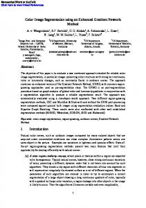
are used as the initial seeds for the SRG procedure. The balance of the paper is organized as follows. An improved isotropic color-edge detector is proposed in Section II . A seeded region growing technique, as well as an algorithm to select the seeds automatically, is introduced in Section III . Application of the proposed automatic image segmentation technique to face detection is discussed in Section IV . We present diverse experimental results in Section V . Conclusions are made in Section VI. Fig. 1. Major steps in our color-edge detection technique.
II. COLOR-EDGE EXTRACTION What are the edges in a digital color image? A first intuitive answer is that the respective brightness values of two neighboring pixels in an edge should be significantly or steadily different. An alternative edge characteristic is that the colors of the neighboring pixels are significantly different, even though their brightness values are very similar. Therefore, both changes in the brightness and changes in the color betweem neighboring pixels should be exploited for more efficient color-edge extraction. Many robust and complex color-edge detection techniques have been proposed [14]–[18]. These sophisticated techniques can provide highly accurate results (a thorough discussion of this body of previous work is, however, beyond the scope of this paper). We choose instead to implement a more simple, though less accurate isotropic edge detector for identifying the geometric structures of an image. The detected edge results can then be improved by integrating them with the results of an SRG procedure. There are two categories of isotropic edge detectors: 1) radient operators and 2) second derivative operators. Gradient operators, such as the Roberts, Prewitt, and Sobel operators [19]–[21], detect the edges by looking for the maximum and minimum in the first derivative of the luminance of an image. The second derivative operators, such as the Marr-Hildreth and Marr-Poggio operators [22], [23], search for zero-crossings in the second derivative of the luminance of an image to find the edges. Despite various shortcomings of these isotropic edge detectors pointed out by Haralick [24] and Canny [25], they remain popular because human beings usually do not show strong directional preferences when detecting edges or boundaries [26]. However, most existing isotropic edge detectors consider only the horizontal and vertical edge patterns. We develop an improved isotropic color-edge detector by including more potential edge patterns and integrating a fast entropic thresholding technique. The major steps of the proposed detector are shown in Fig. 1
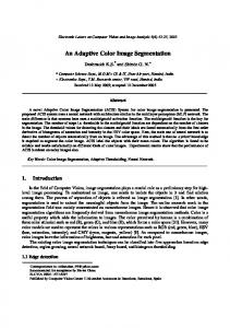
edge extraction procedure. The latter property is very attractive for real-time image processing systems. Since the chrominance components U and V are normally in half-resolution of the luminance Y, a color image of CIF-size, ) pixels of the Y component for example, includes ( ) pixels for each of the U and V components. and ( The luminance component Y of a color image may be taken as , which a two-dimensional (2-D) light-intensity function ) pixels, each with a value of brightness, i.e., contains ( grey level, from 0 to . Grey level 0 is the darkest and grey level is the brightest. In our study, the task of edge extraction is to classify the pixels into two opposite classes: edge versus nonedge. The second-order neighborhood is used to describe the reand its neighboring lationship between the current pixel pixels, as shown in Fig. 2(a) . An edge may pass through the second-order neighborhood of a pixel in one of the four representative patterns shown in Fig. 2(b), namely horizontal, vertical, northeast diagonal, and northwest diagonal. For pixel , , , and denote the edge strength induced by the horizontal, vertical, northeast diagonal, and northwest diagonal edge patterns, respectively. These edge strengths are calculated as a weighted , where the weight coeffisum of the pixel values in cients are given in Fig. 2(b)
(1)
(2)
A. Edge Detection Although the perceptual color spaces (CIE(Lab), HVC, and HSV) may be more suitable for image representation and analysis [37], the YUV color space is selected in this paper, for two reasons. First, the chrominance components (U and V) are explicitly separated from the luminance (Y) component in the YUV model. Second, the YUV space is typically used in most image and video coding standards and therefore the computation burden for format transformation will be avoided in the
indicates the grey level of the pixel at
where .
, The local maximum edge strength of pixel is defined as the maximum of the four edge strengths; i.e.,
(3)
1456
IEEE TRANSACTIONS ON IMAGE PROCESSING, VOL. 10, NO. 10, OCTOBER 2001
Fig. 2. (a) Second-order neighborhood of potential edge patterns.
N(
x; y )
of current pixel (x; y ). (b) Weight coefficients for calculating the H OE , V OE , N OE , and SOE edge strengths
Given an optimal threshold, e.g., , the function classifies the pixels on the luminance component into two opposite classes: edge pixels versus nonedge pixels, as edge pixel
if
nonedge pixel
if (4)
The optimal threshold is automatically determined by the fast entropic thresholding technique, as described in Section II-B . Besides being induced by changes in the luminance component, the edges in a color image can be defined when the chrominance values of neighboring pixels significantly differ. Therefore, an analogous edge detection procedure is further performed on the chrominance components U and V. Since the chrominance components U and V are normally in half-reso) of the luminance component Y with size lution ( ), four neighboring luminance pixels have the same ( chrominance, as edge pixel
where and indicate the local maximum edge strength of the chrominance pixel at and and indicate the respective optimal thresholds. These optimal thresholds are also determined automatically by the fast entropic thresholding technique described in Section II-B. and are calculated on The parameters the basis of the four potential patterns as described above but on the half-resolution chrominance component spaces. Edge results for the three color components are then integrated through the fusion rule, shown in (7) at the bottom of the is classified as an edge pixel if it is so classipage. Pixel fied by at least one of its three color components, in which case is set to 1. Otherwise, it is classified as a nonedge pixel is set to 0. and The obtained color edges can provide a simplified image that preserves the domain geometric structures and spatial relationships found in the original image. They are normally discontinuous or over-detected. Thus, they cannot be used as image content descriptors directly. However, they are very useful for providing the structural seeds of an image.
if B. Fast Entropic Thresholding
nonedge pixel
if
edge pixel
if
nonedge pixel
if
(5)
(6)
edge pixel
To automatically obtain an optimal threshold that is adaptive to the image contents, the entropic thresholding technique is used. The technique is shown to be highly efficient for the two-class data classification problem [27], [28]. To illustrate, let ]. the local maximum edge strength of pixels have range [ In an input image, assume that there are pixels whose local . Given a maximum edge strength has the value , threshold, e.g., , the probability distributions for the edge and
if (7)
nonedge pixel
otherwise
FAN et al.: IMAGE SEGMENTATION BY INTEGRATING COLOR-EDGE EXTRACTION
nonedge pixel classes can be defined, respectively. As they are to be regarded as independent distributions, the probability for can be defined as the nonedge pixels
1457
tropies can then be exploited as
(8) indicates the total number of pixels that have where . the local maximum edge strength features in range can also be defined as The probability for the edge pixels (9) (15) indicates the total number of pixels that have where the local maximum edge strength features in the range . The entropies for these two pixel classes are then given as (10)
(11) selected for performing the The optimal threshold vector nonedge and edge pixel classification has to satisfy the following criterion functions [29]: (12) In order to find the global maximum of (12), the computabecause it takes time to obtain tion complexity is potential the two entropies for each element and there are elements. To reduce the search complexity, a fast algorithm is and proposed that recursively calculates the probabilities and the entropies and , where the computation burden is reduced by calculating the re-normalized part repeatedly. We first define the total number of the pairs in the nonedge and edge classes [the re-normalized parts used in (8) and (9)] when the threshold is set to
(13) The corresponding total number of pairs at global threshold can be calculated as
(14) The recursive iteration property for the two corresponding en-
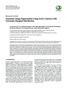
(16) Observe that the complexity of the recursive calculations is reby only adding the incremental part at each itduced to , the re-noreration step. For the partition at threshold in the exmalized parts are always calculated from 0 to haustive search algorithm. But in the proposed fast algorithm, , the re-normalized parts are only calculated from to making it much more efficient. Experimental results have confirmed that the proposed search algorithm is very suitable for real-time image segmentation. C. Performance Evaluation To evaluate the actual performance of the proposed color-edge detector, we tested many images which include variant image components. Since ours is an isotropic edge detector, we compare it with several other well-known isotropic edge detectors. For the traditional isotropic edge detectors, which do not provide automatic selection of the optimal thresholds, we determine their thresholds by our fast entropic technique. Fig. 3(a) gives the original image of “Akiyo.” Fig. 3(b) shows the extracted edges by performing our color-edge detector on the three color components. Fig. 3(c) shows the extracted edges by performing our edge detector on the luminance component only. Observe that our color-edge detector can provide more accurate results — some obvious edges of the color monitors in the image are missed if the edge detector is only performed on the luminance component. The results obtained by the Prewitt, Sobel, Laplacian, and Roberts edge detectors are given in Fig. 3(d)–(g), respectively. Notice that our isotropic color-edge detector can provide more potential edges as compared with these other detectors under the same conditions. Similar results for “Foreman,” “Mobile,” “Flowergarden,” and “Hallmonitor” are given in Figs. 4–7, respectively.
1458
IEEE TRANSACTIONS ON IMAGE PROCESSING, VOL. 10, NO. 10, OCTOBER 2001
Fig. 3. Edge detection performance comparisons based on image “Akiyo”: (a) original image, (b) color edges obtained by our technique, (c) luminance edges obtained by our technique, (d) edges obtained by the Prewitt operator, (e) edges obtained by the Soble operator, (f) edges obtained by the Laplacian operator, and (g) edges obtained by the Roberts operator.
Fig. 4. Edge detection performance comparisons based on image “Foreman”: (a) original image, (b) color edges obtained by our technique, (c) luminance edges obtained by our technique, (d) edges obtained by the Prewitt operator, (e) edges obtained by the Soble operator, (f) edges obtained by the Laplacian operator, and (g) edges obtained by the Roberts operator.
III. REGION-BASED IMAGE SEGMENTATION We have provided simplified geometric structures of the image regions using our color-edge detector. However, these color edges are normally discontinuous or over-detected. Thus they cannot be used directly as the image content descriptors. In the boundary-based image segmentation approach, several post-procedures, such as edge tracking, gap filling, smoothing, or thinning, should be performed on the detected edge points. These post-procedures are expensive. On the other hand, region-based image segmentation techniques can provide the closed region boundaries but the boundaries may be not very accurate. We try to integrate the advantages of both the boundary-based approach and the region-based approach, including avoiding the complex post-procedures required by the latter approach. We select the SRG technique for region growing. whose initial seeds can also be computed automatically from the obtained color-edge regions. Given the seeds, e.g., , , , , SRG segments an image into regions, with the property that each connected component of a region meets
exactly one of the seeds . Moreover, the regions are chosen to be as homogeneous as possible. A. Automatic Seed Generation An obvious way to extend the SRG technique to automatic image segmentation is simply to automate the process of seed selection. One advantage of SRG is that the high-level knowledge of semantic image components can be exploited to select the suitable seeds for more meaningful region growing. This property is very attractive for content-based image database applications. Since most geometric structures of the image regions have been provided by the obtained color edges, the initial seeds for SRG can be generated from these color edges automatically. To this end, the connected edge pixels are first merged together and labeled with the same symbol. A minimum spanning tree is used for representing the relationships among the adja) between two cent edge regions [31]. The centroid ( and , which is defined as adjacent labeled edge regions
FAN et al.: IMAGE SEGMENTATION BY INTEGRATING COLOR-EDGE EXTRACTION
1459
Fig. 5. Edge detection performance comparisons for image “Mobile”: (a) original image, (b) color edges obtained by our technique, (c) luminance edges obtained by our technique, (d) edges obtained by the Prewitt operator, (e) edges obtained by the Soble operator, (f) edges obtained by the Laplacian operator, and (g) edges obtained by te Roberts operator.
Fig. 6. Edge detection performance comparisons based on image “Flowergarden”: (a) original image, (b) color edges obtained by our technique, (c) luminance edges obtained by our technique, (d) edges obtained by the Prewitt operator, (e) edges obtained by the Soble operator, (f) edges obtained by the Laplacian operator, and (g) edges obtained by the Roberts operator.
the algebraic average of the edge pixels in the corresponding regions is calculated as
(17)
if and only if ; otherwise, . The boundary for the same homogeneous region may be partitioned into several adjacent edge regions because the obtained color edges are normally discontinuous. Thus the centroids between several adjacent edge regions may be very close and their colors may be very similar. When that happens, these neighboring similar centroids are merged into one. The refined centroids are taken as the initial seeds , , , , for SRG and these seeds are updated step by step by incorporating the new points. where
B. Seeded Region Growing (SRG) Given the set of seeds, , , , , each step of SRG incorporates one additional pixel into one of the seed sets. These initial seeds are further replaced by the centroids of the gen-
erated homogeneous regions , , , and by incorporating the additional pixels step by step. The pixels in the same region are labeled by the same symbol and the pixels in variant regions are labeled by different symbols. All the labeled pixels are called allocated pixels; the unlabeled pixels are called unallocated pixels. Let be the set of all unallocated pixels which are adjacent to at least one of the labeled regions [10] (18) is the second-order neighborhood of the pixel where ), as shown in Fig. 2(a). For , we have that ( meets just one of the labeled image regions and deto be that index such that fine . is defined as the difference between ) and its adjacent labeled region . the testing pixel at ( is calculated as
(19) , , and indicate the values of the where ), respectively, three color components of the testing pixel (
1460
IEEE TRANSACTIONS ON IMAGE PROCESSING, VOL. 10, NO. 10, OCTOBER 2001
Fig. 7. Edge detection performance comparisons based on image “Hallmonitor”: (a) original image, (b) color edges obtained by our technique, (c) luminance edges obtained by our technique, (d) edges obtained by the Prewitt operator, (e) edges obtained by the Soble operator, (f) edges obtained by the Laplacian operator, and (g) edges obtained by the Roberts operator.
, , and represent the average values of the three color components of the homogeneous region , respectively, and ( ) is the centroid of . If meets two or more of the labeled regions, takes a value meets and is minimized of such that (20) The SRG procedure is repeated until all the pixels in the image have been allocated to the corresponding regions. The definition of (18) and (20) ensures that the final partition of the image is divided into a set of regions as homogeneous as possible on the basis of the given constraints. The results of color-edge extraction and SRG are integrated to provide more accurate image segmentation. The boundaries (boundary pixels) of each homogeneous region are first extracted by determining the first and last pixels for each row and column for the same region and then these first and last pixels are taken as the boundary of the corresponding region. There are four possibilities by integrating the region boundaries (obtained by SRG procedure) and the color edges (obtained by the color-edge detector). The boundary pixels, which are detected as both the region boundaries and the edges, should be pixels on the final region boundary. The region pixels, which are not detected as both the region boundaries and the edges, should be the pixels inside a region. The uncertain pixels which are detected as the region boundaries but are not detected as the edges, may be the discountinuous points and should be refined on the basis of their neighbors. The uncertain pixels which are detected as the edges but are not detected as the region boundaries may be the over-detected edge pixels and should be refined on the basis of their neighbors. The color-edge detector as described in Section II is further performed on the neighborhoods of these uncertain pixels by using a relaxed thresholding procedure [38]. As a result, the region boundaries are eliminated or modified on the basis of these local edges.
There is also a possibility that some of these image regions are actually parts of the same homogeneous region but have been split because the initial given seeds for them are different. Hence, the adjacent regions, which do not have a “significant” edge between them, are also merged together to form a bigger region. This region merging procedure is managed by a minimum spanning tree, which is used for representing the relationships among the adjacent regions. The region relationship graph of the adjacent regions can be further exploited in managing the seeded region aggregation procedure. IV. FACE DETECTION AND HUMAN OBJECT GENERATION Given the homogeneous regions with accurate boundaries, the face detection technique is used to determine which homogeneous regions can be taken as a human face. By taking the detected faces as human object seeds, an automatic semantic human object generation scheme is developed through the seeded region aggregation procedure. A. Skin Color Map Generation In existing skin color segmentation methods, all visible colors are partitioned into two opposite groups: skin color versus nonskin color [32]–[34]. However, two pixels near the boundary of a skin region can be classified into different groups, although their color difference is almost unnoticeable by a human viewer. Moreover, there is a lot of small holes in the skin color regions and a post-procedure is needed to remove these holes. However, the facial features, such as eyes, mouth, nose etc., are also detected as the holes in the skin color segmentation procedure. It is unreasonable to remove these facial features because the objective of face detection is to extract these facial features for face recognition. To avoid these unnatural and instability problems, skin color segmentation is not based on the pixels, but on the obtained homogeneous regions. Following the approach of Wu et al. [35],
FAN et al.: IMAGE SEGMENTATION BY INTEGRATING COLOR-EDGE EXTRACTION
1461
we employ a semi-automatic skin color map generation algorithm, in which the map is generated from a given set of training in the color space face images. For each visible color point (i.e., is a pair of chrominance values), we assign , of how much is likely to correa probability, spond to the skin color (21) denotes the number of times the color point appears within human-identified face regions in the denotes the total number of training images, and appears anywhere in the training images (i.e., times including background, eyes regions, mouth region, etc). Since the chrominance components should be narrowly distributed across a human face region, the span interval for the generated , should be very compact. skin color map,
where
Fig. 8. Definition of rectangular box of a face candidate.
B. Skin Region Detection , in a homogeneous region generated Given a pixel, e.g., as discussed in Sections II and III, its skin color likeness, is computed as (22) is the generated skin color map where ) indicates the values of and of the pixel ( ), respectively. The average skin color similarity, , for an ( identified homogeneous region, e.g., , can then be defined as (23) indicates the total number of pixels in region . The where homogeneous regions whose average skin color similarities are above a given threshold, e.g., , are then taken as the skin color regions is skin region (24) is nonskin region.
Fig. 9.
Front-view face model.
where and indicate the smallest and largest -coordinates of the region’s boundary pixels, respectively, and and indicate the corresponding smallest and largest -coordinates, respectively. In our experimental procedure, we take the acceptable range of aspect ratio to be [0.4,0.85]. Second, we apply a skin area ratio filter to the face candidates remaining after the first step. The basic idea is that the rectangular box of a face candidate, as shown in Fig. 9 , should contain a skin color region (black region the figure) as well as several nonskin color regions (white color regions that correspond to the eyes, eyebrows, mouth, background, etc.). The skin color ratio , which is defined as the ratio between the skin color pixels and the total pixels in the rectangular box, should be within an expected range skin pixel
In practice, is selected on the basis of the set of training face images used for generating the skin color map. C. Face Extraction Of course, not all skin color regions are human face regions. Identifying those skin color regions that resemble a face region is an important step in facial feature extraction. After this step, facial features such as eyes, nose and mouth can be obtained by using suitable geometric constraints. To proceed, we define a “rectangular box,” as shown in Fig. 8 for each obtained skin color region. Since the human face should have an aspect ratio within a narrow range, we first apply anaspect ratio filter to reject the skin color regions that are unlikely to be face candidates. Precisely, this aspect ratio of a region can be defined as (25)
(26)
skin pixel indicates the number of skin color pixels where in the corresponding rectangular box. In our experimental procedure, we require that the skin area ratio of the selected human face region candidates to be in [0.65,0.8]. Third, we apply an ellipse shape filter to the remaining face , its region candidates. For a candidate face region, e.g., weighted centroid is defined as
(27)
is the luminance value of the pixel at ( ). In where addition to this weighted centroid that gives the position of the
1462
IEEE TRANSACTIONS ON IMAGE PROCESSING, VOL. 10, NO. 10, OCTOBER 2001
Fig. 10.
Face detection results for “Foreman”: original images versus face detection results.
face candidate region, the orientation of the face candidate region is defined by an axis that has the lowest moment of rotation. This moment axis is also the line from which the sum of squares of distance from individual pixels is the minimum and its angle can be computed as
(28) indicates the ( )th order central moment for the where . Once the orientation corresponding face candidate region and centroid of a face candidate are known, its major and minor diameters and their lengths can also be determined automatically as shown in Fig. 8 . The ellipse shape model for face cancan then be generated as didate
Fig. 11. Face detection results for “Akiyo”: original images versus face detection results.
(29) and indicate the length of the major and minor where diameters, respectively, represents the “circumference” of the ellipse, and Fig. 12. Region constraint graph for human being object; the extracted human face is taken as the region seed.
(30)
) denotes the principal axis coordinates of the ellipse where ( shape model. The relationships among the weighted centroid, orientation , rectangular box and the major and minor axes are given in Fig. 8 . After the ellipse model for a candidate face , region has been generated, the Hausdorff distance [36], can be used for measuring the similarity between the ellipse model and the corresponding face candidate
(31)
where Euclidean norm;
boundary points on the candidate face region ; boundary points on the generated ellipse model. The ellipse shape filter then rejects those candidate regions for which the computed Hausdorff distance exceeds a specified threshold, e.g., is nonface (32) is face. Since the face region may be partially covered by the hair, etc, the boundary of the detected face region may deviate significantly from the ideal ellipse model; thus the th Hausdorff distance is used in (31). Moreover, the facial features such as eyes, mouth, and nose, can further be detected on the basis of their geometric constraints. A set of face detection results is given in Figs. 10 and 11.
FAN et al.: IMAGE SEGMENTATION BY INTEGRATING COLOR-EDGE EXTRACTION
Fig. 13.
1463
Major steps for semantic human object generation.
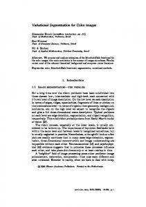
Fig. 14. Segmentation results of “Akiyo.” Frame 249: (a) original image, (b) the obtained color edges, (c) the obtained luminance edges, (d) the obtained chrominance edges, (e) the obtained region boundaries, (f) the obtained human face, (g) the generated seeded semantic human being, and (h) the extracted semantic object. Frame 299: (i) original image, (j) the obtained color edges, (k) the obtained luminance edges, (l) the obtained chrominance edges, (m) the obtained region boundaries, (n) the generated seeded semantic human being, and (o) the extracted semantic object.
D. Human Object Generation It is impossible to design a universal semantic object generation technique which can provide variant semantic objects using the same function. However, semantic object generation for content–based image database applications is possible because the database images can be indexed by selected semantic objects of common interest to human users, such as human beings, cars and airplanes. This interest-based image indexing approach is reasonable because users do not pay equal attention to all the objects present in an image. It reduces the difficulties for automatic semantic object generation—several independent functions can be designed, each handling one type of semantic object. Each function is designed by using an object seed and a region constraint graph (i.e., perceptual model) of the corresponding semantic object.
The selected object seed should represent the distinguishing character of the corresponding semantic object. The region constraint graph can guide how the connected regions of the object seed should be put together for generating that object. The semantic object generation function first tries to identify the object seed from obtained homogeneous regions. It then matches the region constraint graph with the minimum spanning tree (determined by the image segmentation procedure) of the detected object seed. If the object seed is detected and the corresponding region constraint graph is also in good enough matching, a seeded region aggregation procedure is used for merging the adjacent regions of the object seed to produce the semantic object. For example, Fig. 13 illustrates the major steps in our semantic human being generation scheme. As shown, the human face is taken as the seed for object generation and the region con-
1464
IEEE TRANSACTIONS ON IMAGE PROCESSING, VOL. 10, NO. 10, OCTOBER 2001
Fig. 15. Segmentation results of “Foreman.” Frame 14: (a) original image, (b) the obtained color edges, (c) the obtained luminance edges, (d) the obtained chrominance edges, (e) the obtained region boundaries, (f) the obtained human face, (g) the generated semantic human being. Frame 99: (h) the original image, (i) the color edges, and (j) the generated semantic object. Frame 149: (k) the original image, (l) the color edges, (m) the luminance edges, (n) the detected face, and (o) the generated semantic object.
Fig. 16. Segmentation results of “News”: (a) original image, (b) the obtained color edges, (c) the obtained luminance edges, (d) the obtained chrominance edges, (e) the obtained human face for object 1, (f) the obtained human face for object 2, (g) the generated semantic human being for object 1, and (h) the generated semantic human being for object 2.
straint graph (perceptual model) of human beings, as shown in Fig. 12 is used for managing the seeded region aggregation procedure. This perceptual model of human beings can guide how the adjacent regions corresponding to face (or head, taken as object seed), body, arms, legs should be put together. We study semantic human object generation because it is particularly interesting in image database applications. Functions for generating cars, airplanes, etc, will be investigated in future work. V. EXPERIMENTAL RESULTS We report a set of experimental results to show the effectiveness of the proposed algorithms on detecting the color edges, homogeneous regions, faces and semantic human objects. They
serve to illustrate the performance of all the techniques presented in Section II, III, and IV . Four images are used, namely “Akiyo,” “Foreman,” “News,” and “Mother and Daughter.” These images are well-known in the image and video coding community. Fig. 14(a) shows the original image of “Akiyo,” Fig. 14(b) gives the the color edges obtained by this proposed isotropic color-edge detector. Fig. 14(c) is the obtained edges by performing the proposed edge detector only on the luminance component Y. Fig. 14(d) is the obtained edges by performing the proposed edge detector only on the chrominances U and V. Fig. 14(e) is the region boundaries by integrating the results of color edges and SRG. Notice that the homogeneous regions with accurate boundaries are obtained. The filters of skin color,
FAN et al.: IMAGE SEGMENTATION BY INTEGRATING COLOR-EDGE EXTRACTION
1465
Fig. 17. Segmentation results of “Mother and Daughter”: (a) original image, (b) the obtained color edges, (c) the extracted luminance edges, (d) the obtained region boundaries, (e) the obtained human face for “Mother” object, (f) the obtained human face for “Daughter” object, (g) the generated semantic human being for “Daughter” object, and (h) the generated semantic human being for “Mother” object.
aspect ratio, skin area ratio and ellipse shape are used to detect the homogeneous regions that can be taken as human faces. Fig. 14(f) is the human face obtained by the proposed face detection technique in Section IV. Fig. 14(g) is the corresponding seeded semantic human object. Fig. 14(h) is the detected semantic object. Similar results for another frame of the “Akiyo” video are also given in Fig. 14 . In addition, Figs. 15–17 show results for “Foreman,” “News,” and “Mother and Daughter,” respectively. VI. CONCLUSION A new automatic image segmentation algorithm is proposed in this paper. The color edges are first obtained by an improved isotropic color-edge detector and the centroids between the adjacent edge regions are taken as the initial seeds for region growing. Moreover, the results of color-edge extraction and SRG are integrated to provide more accurate segmentation of images. Application of the proposed image segmentation algorithm to automatic face detection is also discussed. Moreover, a novel semantic object generation scheme is proposed using a seeded region aggregation procedure. By including a temporal tracking procedure [38], semantic video objects can also be supported. Such a semantic object generation scheme should be very attractive for content-based multimedia database applications. REFERENCES [1] M. Sonka, V. Hlavac, and R. Boyle, Image Processing Analysis and Machine Vision. London, U.K.: Chapman & Hall, 1999. [2] Y. W. Lim and S. U. Lee, “On the color image segmentation algorithm based on the thresholding and the fuzzy C-means technique,” Pattern Recognit., vol. 23, no. 9, pp. 935–952, 1990. [3] P. K. Sahoo, S. Soltani, and A. K. C. Wong, “A survey of thresholding techniques,” Comput. Vis. Graph. Image Process., vol. 41, pp. 233–260, 1988. [4] N. Pal and S. Pal, “A review on image segmentation techniques,” Pattern Recognit., vol. 26, pp. 1277–1294, 1993. [5] M. Kass, A. Witkin, and D. Terzopoulos, “Snakes: Active contour models,” in Proc. 1st ICCV, 1987, pp. 259–267.
[6] P. L. Palmer, H. Dabis, and J. Kittler, “A performance measure for boundary detection algorithms,” Comput. Vis. Image Understand., vol. 63, pp. 476–494, 1996. [7] R. M. Haralick and L. G. Shapiro, “Survey: Image segmentation techniques,” Comput. Vis. Graph. Image Process., vol. 29, pp. 100–132, 1985. [8] Y. -L. Chang and X. Li, “Adaptive image region-growing,” IEEE Trans. Image Processing, vol. 3, pp. 868–872, 1994. [9] S. A. Hijjatoleslami and J. Kittler, “Region growing: A new approach,” IEEE Trans. Image Processing, vol. 7, pp. 1079–1084, 1998. [10] R. Adams and L. Bischof, “Seeded region growing,” IEEE Trans. Pattern Anal. Machine Intell., vol. 16, pp. 641–647, 1994. [11] T. Pavlidis and Y. T. Liow, “Integrating region growing and edge detection,” IEEE Trans. Pattern Anal. Machine Intell., vol. 12, pp. 225–233, 1990. [12] J. Haddon and J. Boyce, “Image segmentation by unifying region and boundary information,” IEEE Trans. Pattern Anal. Machine Intell., vol. 12, pp. 929–948, 1990. [13] C. Chu and J. K. Aggarwal, “The integration of image segmentation maps using region and edge information,” IEEE Trans. Pattern Anal. Machine Intell., vol. 15, pp. 1241–1252, 1993. [14] Nevatia, “A color-edge detector and its use in scene segmentation,” IEEE Trans. Syst., Man, Cybern., vol. SMC-7, pp. 820–826, 1977. [15] V. S. Nalwa and T. O. Binford, “On detecting edges,” IEEE Trans. Pattern Anal. Machine Intell., vol. PAMI-8, pp. 699–714, 1986. [16] M. A. Ruzon and C. Tomasi, “Color-edge detection with the compass operator,” in IEEE Conf. CVPR, 1999, pp. 160–166. [17] M. D. Heath, S. Sarkar, T. Sanocki, and K. W. Bowyer, “Arobuts visual method for accessing the relative performance of edge-detection algorithm,” IEEE Trans. Pattern Anal. Machine Intell., vol. 19, pp. 1338–1359, 1997. [18] R. J. Qian and T. S. Huang, “Optimal edge detection in two-dimensional images,” IEEE Trans. Image Processing, vol. 5, pp. 1215–1220, 1996. [19] J. Prewitt, “Object enhancement and extraction,” in Picture Processing and Psychopictures, B. Lipkin and A. Rosenfeld, Eds. New York: Academic, 1970. [20] L. G. Roberts, “Machine perception of three-dimensional solids,” in Optical and Eletrooptical Information Processing, J. T. Tripperts, Ed. Cambridge, MA: MIT Press, 1965. [21] L. Davis, “Survey of edge detection techniques, computer vision,” Graph. Image Process., vol. 4, pp. 248–270, 1975. [22] D. Marr and E. Hildreth, “Theory of edge detection,” Proc. R. Soc. Lond. B, vol. 207, pp. 187–217, 1980. [23] D. Marr and T. Poggio, “A computational theory of human stero vision,” Proc. R. Soc. Lond. B, vol. 204, pp. 301–328, 1979. [24] R. Haralick, “Digital step edges from zero crossing of second directional derivatives,” IEEE Trans. Pattern Anal. Machine Intell., vol. PAMI-6, pp. 58–68, 1984. [25] J. Canny, “A computational appraoch to edge detection,” IEEE Trans. Pattern Anal. Machine Intell., vol. PAMI-8, pp. 679–698, 1986.
1466
[26] E. Hildreth, “The detection of intensity changes by computer and biological vision systems,” Comput. Vis. Graph. Image Process., vol. 22, pp. 1–27, 1983. [27] J. Fan, R. Wang, L. Zhang, D. Xing, and F. Gan, “Image sequence segmentation based on 2-D temporal entropy,” Pattern Recognit. Lett., vol. 17, pp. 1101–1107, 1996. [28] J. Fan, L. Zhang, and F. Gan, “Spatiotemporal segmentation based on spatiotemporal entropic thresholding,” Opt. Eng., vol. 36, pp. 2845–2851, 1997. [29] H. D. Cheng, Y. H. Chen, and X. H. Jiang, “Thresholding using twodimensional histogram and fuzzy entropy principle,” IEEE Trans. Image Processing, vol. 9, pp. 732–735, 2000. [30] P. V. Henstock and D. M. Chelberg, “Automatic gradient threshold determination for edge detection,” IEEE Trans. Image Processing, vol. 5, pp. 784–787, 1996. [31] A. Tremeau and P. Colantoni, “Region adjacent graph applied to color image segmentation,” IEEE Trans. Image Processing, vol. 9, pp. 735–744, 2000. [32] G. Wei and I. K. Sathi, “Face detection for image annotation,” Pattern Recognit. Lett., vol. 20, pp. 1313–1321, 1999. [33] D. Chai and K. N. Ngan, “Face segmentation using skin-color map in videophone applications,” IEEE Trans. Circuits Syst. Video Technol., vol. 9, pp. 551–564, 1999. [34] J. Cai and A. Goshtasby, “Detecting human faces in color images,” Image Vis. Comput., vol. 18, pp. 63–75, 1999. [35] H. Wu, Q. Chen, and M. Yachida, “Face detection from color images using a fuzzy pattern matching method,” IEEE Trans. Pattern Anal. Machine Intell., vol. 21, pp. 557–563, 1999. [36] D. P. Huttenlocher, G. Klanderman, and W. Rucklidge, “Comparing images using the Hausdorff distance,” IEEE Trans. Pattern Anal. Machine Intell., vol. 15, pp. 850–863, 1993. [37] Y. Gong and M. Sakauchi, “Detection of regions matching specified chromatic features,” Comput. Vis. Image Understand., vol. 61, pp. 263–269, 1995. [38] J. Fan, G. Fujita, M. Furuie, T. Onoye, I. Shirakawa, and L. Wu, “Automatic moving object extraction toward compact video representation,” Opt. Eng., vol. 39, no. 2, pp. 438–452, 2000.
Jianping Fan received the M.S. degree in theoretical physics from Northwestern University, China, in 1994, and the Ph.D. degree in optical storage and computer science from Shanghai Institute of Optics and Fine Mechanics, The Chinese Academy of Sciences, China, in 1997. He spent six months at the Department of Computer Science, Fudan University as a Researcher. From 1998 to 1999, he was JSPS Researcher at the Department of Information Systems Engineering, Osaka University, Osaka, Japan, where he worked on VLSI design for very low bit-rate video communication. From 1999 to 2001, he was a Visiting Scholar at the Department of Computer Science, Purdue University, West Lafayette, IN. He is now an Assistant Professor with the Department of Computer Science, University of North Carolina at Charlotte. His research interests include adaptive video coding, video analysis, video indexing, error correction codes, and nonlinear systems. Dr. Fan holds two Chinese national awards for the promotion of science and technology.
IEEE TRANSACTIONS ON IMAGE PROCESSING, VOL. 10, NO. 10, OCTOBER 2001
David K. Y. Yau (S’93–M’97) received the B.Sc. (first class honors) degree from the Chinese University of Hong Kong and the M.S. and Ph.D. degrees from the University of Texas at Austin, all in computer sciences. From 1969 to 1990, he was with the Systems and Technology group of Citibank, NA. He was the recipient of an IBM graduate fellowship and is currently an Assistant Professor of Computer Sciences at Purdue University, West Lafayette, IN. Dr. Yau received an NSF Career Award in 1999, for research on network and operating system architectures and algorithms for quality of service provisioning. He is a Member of the ACM.
Ahmed K. Elmagarmid (M’88–SM’93) received the M.S. and Ph.D. degress in computer and information sciences from The Ohio State University (OSU), Columbus, in 1980 and 1985, respectively. He is now a Professor of Computer Science at Purdue University, West Lafayette, IN, as well as an Industry Consultant. His areas of research interests are data quality, video databases, heterogeneous databases, and distance learning. Dr. Elmagarmid received a National Science Foundation PYI Award in 1988 and was named a “Distinguished Alumnus” of OSU in 1993, and the University of Dayton in 1995. He is the Founding Editor-in-Chief of International Journal on Distributed and Parallel Databases. He serves as a Editor of Information Sciences Journal, International Journal of Communication Systems, and the book series Advances in Database Systems (Norwell, MA: Kluwer, 2000). He has served on the editorial board of IEEE TRANSACTIONS ON COMPUTERS. He is a Chair of the steering committee of the Symposium on Research Issues on Data Engineering and was one of its founders; he serves on the steering committee of IEEE ICDE and has served on its program chair and general chair. He has served on various program and organization committees. He is a member of the ACM.
Walid G. Aref (S’90–M’93) received the Ph.D. degree in computer science from the University of Maryland, College Park, in 1993. He has been with Matsushita Information Technology Laboratory and the University of Alexandria, Egypt. Currently, he is an Associate Professor at the Department of Computer Science, Purdue University, West Lafayette, IN. His current research interests include efficient query processing and optimization algorithms and data mining in spatial and multimedia databases. Dr. Aref is a member of the ACM.