Twist optimization of a helicopter rotor in hover is presented using ... Twist optimization results are presented for three tip Mach numbers, and the effects of ...
JOURNAL OF AIRCRAFT Vol. 47, No. 6, November–December 2010
Computational-Fluid-Dynamics-Based Twist Optimization of Hovering Rotors C. B. Allen,∗ T. C. S. Rendall,† and A. M. Morris‡ University of Bristol, Avon, England BS8 1TR, United Kingdom DOI: 10.2514/1.C000316 Twist optimization of a helicopter rotor in hover is presented using compressible computational fluid dynamics as the aerodynamic model. A domain-element shape parameterization method has been developed, which solves both the geometry control and the volume mesh deformation problems simultaneously, using radial basis function global interpolation. This provides direct transfer of domain-element movements into deformations of the design surface and the computational fluid dynamics volume mesh, which is deformed in a high-quality fashion. The method is independent of mesh type (structured or unstructured), and it has been linked to an advanced parallel gradient-based algorithm, for which independence from the flow solver is achieved by obtaining sensitivity information by finite differences. This has resulted in a flexible and versatile modular method of wraparound optimization. Previous fixedwing results have shown that a large proportion of the design space is accessible with the parameterization method, and heavily constrained drag optimization demonstrated significant performance improvements. In the present work, the method is extended to a rotor blade, and this is optimized for minimum torque in hovering flight with strict constraints. Twist optimization results are presented for three tip Mach numbers, and the effects of different parameterization levels are analyzed using various combinations of two levels: global and local. Torque reductions of over 12% are shown for a fully subsonic case, and for over 24% for a transonic case, using only three global and 15 local twist parameters.
a Reynolds-averaged Navier–Stokes-based optimization of a rotor is presented, but it is achieved with extremely low-density grids and incorporates a very small number of design variables. This has recently been extended to a discrete adjoint approach [22], again with a coarse mesh and using few parameters (13 and 25 are used). Nielsen et al. [27] also uses a discrete adjoint approach, using 44 parameters: 20 section thicknesses and 24 section camber parameters. A composite objective function is also considered. Nadarajah et al. [23] and Nadarajah and Tatossian [24] presented optimization of the Caradonna and Tung [28] two-bladed rotor (as considered here) using an adjoint approach, and they demonstrated significant torque reduction, using detailed aerofoil surface changes, with the planform remaining constant and no moment constraints. Choi et al. [25,26] also used an adjoint approach with the UH-60A blade, coupled with a trimming algorithm, and over 100 design variables were used, including section geometries. Both of the latter methods incorporate a frequency domain approach, and they have also been extended to initial forward-flight optimization although, understandably, only a small number of time instances were used. The research presented here is aimed at the development of a modularized, generic optimization tool that is flow-solver- and meshtype-independent and sufficiently flexible to be applicable to any aerodynamic problem: rotor blades in hover in this case. The key aspect of a flexible optimization and design process is an effective geometry parameterization process that allows sufficient design space investigation and is robust enough to be applicable to any geometry or design surface. Furthermore, a small number of design parameters is desirable, particularly if using a finite-difference gradient evaluation. Related to the surface control is the required volume mesh deformation or regeneration once the design surface has been deformed, and mesh deformation is much preferred to avoid introducing differing discretization error. To satisfy these requirements, an efficient domain-element shape parameterization method has been developed by the authors and presented previously for CFD-based shape optimization in two dimensions [29], and three-dimensional fixed-wing optimizations [30,31], and it is applied to a rotor blade here. The parameterization technique, surface control, and volume mesh motion are all accomplished through the use of global interpolations using radial basis functions, wherein global interpolation is used to provide direct transfer of domain-element movements into deformations of the design surface and the CFD volume mesh, which is deformed in a high-quality
I. Introduction UMERICAL simulation methods (of many fidelity levels) are now used routinely in industrial design, and increasing computer power has resulted in their increasing use in optimization. Integrating an effective geometry control method with an aerodynamic model and a numerical optimization scheme can result in an aerodynamic shape optimization approach, and this is invaluable in the design stage. Computational fluid dynamics (CFD) are at the forefront of aerodynamic analysis capabilities, and the application of numerical optimization algorithms with such analysis has already produced notable results [1–3]. Compressible CFD has been used in numerous optimizations of two-dimensional aerofoil sections [4–7], three-dimensional aircraft [8–12], and three-dimensional aeroelastic aircraft [13,14], but little has been achieved in the way of rotors, primarily due to the high cost. High-density and high-quality grids are necessary to capture the vortical wake, and long solution integration times are required to develop and capture this wake when compared with its fixed-wing counterpart [15–18]; this can result in huge computational power requirements to optimize such a system. There are also two distinct flow regimes, hover and forward flight, and good performance in one is unlikely to be carried over to the other. Aerodynamic optimization has been applied previously to rotors in hover but mainly with lowfidelity aerodynamics and only gross geometric changes (see, for example, [19]), with only a few notable results using compressible CFD: those of ONERA [20–22], Nadarajah et al. [23], Nadarajah and Tatossian [24], Choi et al. [25,26], and Nielsen et al. [27]. In [20,21],
N
Presented as Paper 2010-0676 at the AIAA 48th Aerospace Sciences Meeting, Orlando, FL, 4–7 January 2010; received 18 February 2010; revision received 13 June 2010; accepted for publication 15 June 2010. Copyright © 2010 by C. B. Allen. Published by the American Institute of Aeronautics and Astronautics, Inc., with permission. Copies of this paper may be made for personal or internal use, on condition that the copier pay the $10.00 per-copy fee to the Copyright Clearance Center, Inc., 222 Rosewood Drive, Danvers, MA 01923; include the code 0021-8669/10 and $10.00 in correspondence with the CCC. ∗ Professor of Computational Aerodynamics, Department of Aerospace Engineering. Senior Member AIAA. † Lecturer in Aerodynamics, Department of Aerospace Engineering. Member AIAA. ‡ Postdoctoral Researcher, Department of Aerospace Engineering. 2075
2076
ALLEN, RENDALL, AND MORRIS
fashion. The properties of the parameterization method developed mean that design parameters of any scale may be used, allowing a hierarchy ranging from detailed surface changes to large-scale planform changes; changes of any size can be made to the design surface without the requirement for regeneration of a CFD volume mesh, and the resulting deformed volume mesh remains of high quality [32–35]. The remaining tools required for optimization are effective parameter sensitivity evaluation and an optimization algorithm. To achieve modularity and flow-solver independence, a finite-difference approach to parameter sensitivities has been adopted, and so a small number of design parameters is essential. This shape parameterization method has been coupled to an advanced gradient-based constrained optimization algorithm, and the optimization suite has been parallelized to allow optimization of three-dimensional bodies in practical times. The objective of the research presented here is the extension of this versatile method for aerodynamic optimization to threedimensional helicopter rotor blades. Global and coarse local design variables are applied here and, initially, only twist variations are considered. This was done for two reasons. First, the general framework could be tested for rotors before increasing the level of design parameters. Second, the feasible sequential quadratic programming (FSQP) optimization scheme could be validated and the effects of global and more local parameters investigated. Optimization using just three global twist parameters has been compared with that using the local twist of 15 individual domainelement slices to analyze the importance of the parameters and whether intermediate level parameters perform better than global ones, and these results are presented here. Furthermore, to perform a complete validation of the approach and investigate the available design space, these two levels of variables have also been combined: first run together (i.e., an 18 global and local twist parameter case) and then run in series (by running the 15 local twist case from the converged three global twist case), and these results are also presented.
II.
Domain-Element Parameterization
There have been numerous parameterization methods presented for CFD shape optimization, and these can be split into those that parameterize the aerodynamic mesh or those that parameterize the design geometry from which a mesh is generated. Grid parameterization methods are generally independent of the mesh generation package, so they require a mesh deformation algorithm but allow the use of previously generated meshes for optimization. Methods of this nature include discrete [1,36,37], analytical, basis vector [38], free-form deformation [39], domain-element methods,§ and the recently published control grid approach [40]. Geometry parameterization methods are inherently linked with the mesh generation package, and optimization requires automatic mesh generation tools. Methods of this nature include partial differential equation methods [41,42], polynomial or spline [43] methods, CAD and, recently, class function/shape function transformation [44,45] methods. The reader is referred to [46–49] for reviews of parameterization methods. Grid parameterization methods offer the most flexibility by allowing independence from both the mesh generation tools and the mesh structure. Furthermore, mesh regeneration introduces the problem of varying the discretization error. Hence, although a mesh deformation scheme is required, and this is a significant issue, the grid parameterization and deformation approach is much preferred. The efficient parameterization method here links a set of aerodynamic mesh points to a domain element that controls the shape of the design. The domain element is automatically positioned around the exterior of the design. At the center of this parameterization technique is a multivariate interpolation using radial basis functions, and this provides a direct mapping between the domain element, the surface geometry, and the locations of §
Data available at http://www.optimalsolutions.us/ [retrieved 2008].
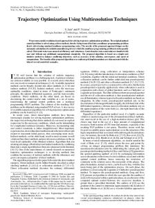
Fig. 1
Initial domain element and rotor surface.
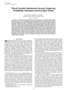
the grid points in the CFD volume mesh. A global dependence can be evaluated between the control points (the domain-element nodes) and the grid nodes, and this has many advantages: the mapping is only required once for the initial design, as the values of the parametric coordinates of the grid points with respect to the domain element remain constant throughout the optimization. Updates to the geometry and the corresponding mesh are provided simultaneously by application of multivariate interpolation, and this is extremely fast and efficient and results in very high-quality mesh deformation, even for large deformations [32–35]; the approach is meshless, so it requires no connectivity and is applicable to any mesh type. Domain-element points and volume mesh points are simply treated as independent point clouds; the system is only the size of the number of domain-element nodes, and so it is not related to the mesh size. The Caradonna and Tung two-bladed rotor [28] is considered here, and the domain element is defined to consist of 17 twodimensional slices evenly distributed along the span. Figure 1 shows the domain-element parameterization extended to this blade for the one million cell mesh used later. Instead of using the individual locations of each domain-element node, an intuitive set of applicable shape deformation design variables have been developed by inverse design techniques [29], and each two-dimensional slice can have up to 22 design variables associated with it; these control local surface changes. It is important to note that the parameterization is fully three-dimensional, such that deformations due to a movement of the domain-element two-dimensional slice smoothly extend in the spanwise direction as well, so that no linear interpolation is required between slices. Combined with this series of local surface changes are design variables that are truly three-dimensional by definition; these control planform changes include angle of attack, twist, sweep, and anhedral/dihedral distributions. The domain-element method allows for independent multiple levels of design variables and, so far, three levels have been adopted: 1) global design variables, such as twist or chord distribution; 2) local coarse, which is the local chord, twist, and thickness of each two-dimensional domain-element slice; and 3) local fine, which is the fine surface design variables, such as leading-edge control. Of interest here are global and local coarse parameters, and only twist parameters are considered in this paper. Figure 2 shows examples of the parameters used here. The first image shows the deformation for an exaggerated global linear rootto-tip twist; the deformed domain element and resulting blade surface are shown. The second image shows a positive twist, about the quarter chord position, of the 16th domain-element slice, and the third image shows an antisymmetric twist of the 13th and 16th domain-element slices. The flexibility of the approach and the smoothness of the deformed surface is clear; the volume mesh is deformed in the same smooth fashion, and so no mesh regeneration is required.
ALLEN, RENDALL, AND MORRIS
Fig. 2
2077
Deformed domain element and rotor surface.
III. Optimization Approach
IV. Test Case and Flow-Solver Validation
Optimization of the aerodynamic performance of a solid body (aerofoil/wing/rotor blade) will only be relevant if it can be achieved while satisfying aerodynamic and geometric constraints (minimum thickness, minimum volume, minimum lift, maximum pitching moment, etc.). Unconstrained optimizations can incorporate constraints by using a penalty function for design parameters that take the design near or beyond the constraint boundary, but these methods are now considered inefficient and have been replaced by methods that focus on the solution of the Kuhn–Tucker equations. A FSQP [50–52] algorithm is employed in the current research and represents the forefront of nonlinear programming techniques. The optimization process obtains the values of a set of design variables that can, in some way, be defined as optimal. Objective function(s), determined to be function(s) of the design variables, are minimized and can be subject to equality constraints, inequality constraints, and/or parameter bounds. Optimization is made independent from the flow solver by obtaining sensitivity information by finite differences using a symmetric central-difference stencil; that is, one positive and one negative perturbation are considered for each design variable. The entire optimization suite has been parallelized using a message-passing interface. The optimization algorithm comprises modules for objective and constraint function evaluations, gradients of objective and constraint functions, and a sequential quadratic programming numerical optimizer for updates. Function evaluations and optimizer updates occur on the master and, for gradient evaluation using a finite-difference methodology, the sensitivity for each design variable is obtained by the relative change in the value of objective (or constraint function) due to a geometric perturbation, and each perturbation can be considered independently. Hence, the gradient evaluation module has been parallelized to allow parallel evaluation of the required sensitivities, such that each CPU can control the geometry (and CFD volume mesh) corresponding to a different design variable and call the flow solver. Flow-solver results are then returned to the master for optimizer updates. This gradient evaluation module remains independent of the flow solver, so either a serial or parallel version of the flow solver may be called.
The Caradonna and Tung two-bladed rotor [28] is a rectangular blade, aspect ratio 6, constant NACA0012 section with no twist or taper. The case chosen was the 8� pitch case, and optimization was performed for three tip Mach numbers. A tip Mach number of 0.612 was first used, since this gives a fully subsonic case, and torque reduction could be attributed to reduction of induced power; higher values of 0.794 and 0.877 were also used, since these would demonstrate the extra effect of wave drag due to the transonic regions, and the effect of tip speed would be clear. A one million cell structured multiblock mesh was used, generated by the techniques of Allen [53]. Figure 3 shows the domain and block boundaries, the grid in the rotor disk, and the structure near the blade tip. The far field is set to approximately 20 chords from the blade. A.
Flow Solver
The flow solver used is a structured multiblock finite-volume unsteady, inviscid upwind code [54,55] using the flux vector splitting of van Leer [56,57] and the implicit pseudotime stepping scheme of Alonso and Jameson [58] and Jameson [59]. Convergence acceleration is achieved through a multigrid [17,55]. The code has been parallelized and shown to have very good scaling properties [15], although the optimization here is performed as data parallel, so each CPU spawns its own scalar call to the solver. The method solves the Euler equations in integral form and, for hovering rotor cases, the three-dimensional unsteady Euler equations are transformed to a blade-fixed rotating reference frame. In this frame, the hover case is then a steady problem. If the frame rotates with angular velocity ! � ��x ; �y ; �z �T , and the absolute velocity vector in the rotating frame is denoted by qr � �ur ; vr ; wr �T, the resulting Euler equations in integral form are then Z Z Z d Ur dVr � Fr :nr dSr � Gr dVr � 0 (1) dt Vr @Vr Vr where Vr is the control volume, @Vr is the control volume boundary, and
2078
ALLEN, RENDALL, AND MORRIS
Fig. 3
R/Rtip = 0.50
1.5
1
1
0.5
0.5
0
0
-0.5
-0.5
-1
-1 0
0.2
0.4
0.6
R/Rtip = 0.80
1.5
-Cp
-Cp
Domain and block boundaries, rotor disk mesh, and mesh near tip.
0.8
1
0
0.2
0.4
x/c R/Rtip = 0.89
0.8
1
R/Rtip = 0.96
1.5
1
1
0.5
0.5
-Cp
-Cp
1.5
0.6
x/c
0
0
-0.5
-0.5
-1
-1
Numerical Experimental
0
0.2
0.4
0.6
0.8
1
0
0.2
x/c
Fig. 4
0.4
0.6
x/c
Surface pressure coefficient: MTip � 0:612.
0.8
1
2079
ALLEN, RENDALL, AND MORRIS
R/Rtip = 0.50
1
1
0.5
0.5
0
0
-0.5
-0.5
-1
-1 0
0.2
0.4
0.6
R/Rtip = 0.80
1.5
-Cp
-Cp
1.5
0.8
1
0
0.2
0.4
x/c R/Rtip = 0.89
0.8
1
R/Rtip = 0.96
1.5
1
1
0.5
0.5
-Cp
-Cp
1.5
0.6
x/c
0
0
-0.5
-0.5
-1
-1
Numerical Experimental
0
0.2
0.4
0.6
0.8
1
0
0.2
0.4
x/c
Fig. 5
0.5
0.5
-Cp
-Cp
1
0
-0.5
-1
-1 0.4
0.6
0.8
1
0
0.2
0.4
x/c
1
R/Rtip = 0.96
1.5
1
1
0.5
0.5
-Cp
-Cp
0.6
x/c
R/Rtip = 0.89
1.5
0.8
0
-0.5
0.2
1
R/Rtip = 0.80
1.5
1
0
0.8
Surface pressure coefficient: MTip � 0:794.
R/Rtip = 0.50
1.5
0.6
x/c
0
0
-0.5
-0.5
-1
-1
Numerical Experimental
0
0.2
0.4
0.6
0.8
1
0
0.2
0.4
x/c
Fig. 6
0.6
x/c
Surface pressure coefficient: MTip � 0:877.
0.8
1
2080
ALLEN, RENDALL, AND MORRIS
Table 1
Rotor optimization results MTip � 0:612
V. Rotor Aerodynamic Optimization The domain-element parameterization and advanced optimization approaches have been previously presented for two-dimensional heavily constrained aerofoil optimization [29], three-dimensional fixed-wing [30,31], and initial rotor optimizations [60]. A detailed analysis of rotor optimization using global and local coarse levels of twist parameters is presented here.
Parameters/Evolutions
CT =� (0.0522) Cmx Cmy Volume Cmz a
3/9
15/41
0.00 �7:99 0.00 0.00 �10:60
0.00 �8:47 0.00 0.00 �11:95
18/30
3 then 15a/27 (9 and 18)
% Differences 0.00 �9:53 0.00 0.00 �11:99
0.00 �10:05 0.00 0.00 �12:33
A.
Three global then 15 local twists.
Table 2 Rotor optimization results. MTip � 0:794 Parameters/Evolutions
CT =� (0.0549) Cmx Cmy Volume Cmz a
3/12
15/54
0.00 �11:98 �84:05 0.00 �16:15
0.00 �11:07 �81:75 0.00 �16:94
18/44
3 then 15a/33 (12 and 21)
% Differences 0.00 �11:22 �74:41 0.00 �17:68
0.00 �12:18 �63:48 0.00 �18:13
Three global then 15 local twists.
Table 3
Rotor optimization results MTip � 0:877 Parameters/Evolutions 3/18
CT =� (0.0559) Cmx Cmy Volume Cmz a
0.00 �14:77 �85:59 0.00 �22:52
15/57
18/51
% Differences 0.00 0.00 �13:22 �14:63 �57:30 �49:03 0.00 0.00 �23:32 �23:79
3 then 15a/35 (18 and 17) 0.00 �14:99 �61:02 0.00 �24:31
Three global then 15 local twists.
3 � 6 �ur 7 7 6 7 Ur � 6 6 �vr 7; 4 �wr 5 E 2
3 ��qr � �! � x � 6 �ur �q � �! � x � � Pir 7 r 7 6 7 Fr � 6 6 �vr �qr � �! � x � � Pjr 7 4 �wr �q � �! � x � � Pkr 5 r E�qr � �! � x � � Pqr 3 2 0 6 ��! � q :ir 7 7 6 r 7 Gr � 6 6 ��! � qr :jr 7 4 ��! � q :kr 5 r 0 2
(2)
Here, Gr is the source term resulting from the transformation, and x � �xr ; yr ; zr �T is the coordinate vector. The equation set is closed by � � � (3) P � �� � 1 E � q2r 2
B.
Hover Results
Figures 4–6 show sectional pressure coefficient variations at four radial stations, compared with the experiment, for the three tip Mach numbers considered. These all show good agreement although, as expected, the shock strength is slightly larger than the experimental data at the highest Mach number. The computed thrust coefficients, i.e., the constraints for the optimizations, are shown in brackets in the results Tables 1–3.
Parameters Investigated
As an initial optimization, to validate the optimizer and test the effects of local and global variables, only twist variables were included. The basic case used only three design variables: blade pitch, linear root-to-tip twist, and nonlinear 1=R root-to-tip twist. In fact, to ensure no nonphysical deformation of the blade root, the deformations begin at the third domain-element section; the first section is fixed, and the second section moves approximately one third of the third domain-element section’s motion to avoid a discontinuity there. To compare the effects of local and global parameters, the local coarse parameters were taken as the individual twists of each of the 15 moving domain-element sections. Once these parameters had been used, the robustness of the optimization approach could be investigated by combining the two levels of parameters (i.e., 18 local and global parameters) to ensure the same level of torque reduction could be achieved. As a final check, the converged three-global-parameter case was used as the starting point for the 15-local-twist case. Hence, for the three tip Mach numbers, results are presented for 1) 3 global twists, 2) 15 local domainelement slice twists, 3) 18 twists: 3 global plus 15 local domainelement slice twists, and 4) 3 global twists run to convergence, then 15 local domain-element slice twists run from this result. B.
Optimization Results
The same three tip Mach number cases were used, and optimizations were run in parallel on 4, 16, or 19 CPUs (one per variable plus one for the master process). The cases were all run with the following strict constraints: 1) The objective was to minimize torque. 2) The first constraint, on thrust, was CT CT (original). 3) The second constraint, on bending moment, was Cmx � Cmx (original). 4) The third constraint, on pitching moment, was jCmy j � jCmy j (original). 5) The fourth constraint, on internal volume, was Vint Vint (original). Tables 1–3 show the results of the four optimizations for the three tip speeds. Hence, all have resulted in a significant reduction in torque. The loading distributions and twist distributions along the blade for the MTip � 0:612 case are shown in Fig. 7 for the original and four optimized blades. Considering Table 1, it is clear that the threeglobal-twist case converges very quickly and produces excellent results. The 15-local-twist case allows more flexibility and gives a slightly better result, but it is the most expensive. It is assumed this is due to the fact that the individual twists must also be used by the optimizer to ensure the constraints are not violated. Combining the three global and 15 local twists offers the best of the three parameter options, allowing the finer control plus the global pitch to be used effectively to control the thrust. This is a good check of the optimizer, and it is reassuring that the two sets of combined parameters produced a result at least as good as any individually. However, the design space allowed by these 18 parameters is still large, and the best option appears to be a two-stage process: converge the three global parameters first, to obtain most of the benefits, then restart from this with the 15 local variables. This second stage allows fine control, without having to navigate through the larger design space in the first place. It should be noted how effective the global variables are, though; only nine evolutions are required with three parameters to obtain a 10.6% torque reduction. The best torque reduction is only 1.7% more than this, but it requires a further 18 evolutions with 15
ALLEN, RENDALL, AND MORRIS
Fig. 7
Loading and twist distributions: MTip � 0:612.
Fig. 8
Loading and twist distributions: MTip � 0:794.
parameters. Considering the twist and loading distributions, it appears the optimizer has attempted to deform the blade toward the minimum induced power condition: that is, toward a linear loading distribution. This is as expected for the subsonic case. This increased twist, and subsequent movement inboard of load, has also resulted in a reduction in the root moment in all cases. The loading distributions and twist distributions along the blade for the two transonic cases are shown in Figs. 8 and 9 for the original and four optimized blades. Considering all three cases, there is a remarkably consistent trend. For all of the cases, the three global twists converge the quickest and produce the lowest torque reduction although still most of the maximum achievable; the 15 local twists converge the slowest, and produce the next largest reduction; the combined three global and 15 local twists converge slightly faster
Fig. 9
2081
than the 15, and they produce a further slight increase in torque reduction; and the two-stage process is the second fastest to converge, and it produces the largest torque reduction. Sample convergence histories are presented in Fig. 10 for the different optimizations. These are similar for the three tip speeds, so only the Mach 0.794 case is shown. These clearly demonstrate how effective the three global twists are and how rapidly they converge; the first nine evolutions in the three global followed by 15 local twists case are using only the three global twists. For both transonic cases, the optimizer has not modified the twist toward the minimum induced power condition, since there is now the wave drag component due to the transonic region. Hence, there are high local parameter sensitivities associated with the outer sections attempting to reduce wave drag by reducing the transonic region, and
Loading and twist distributions: MTip � 0:877.
2082
ALLEN, RENDALL, AND MORRIS
Fig. 10 Convergence histories: MTip � 0:794 (15 twists, 18 twists, and 3 � 15 twist parameters).
this explains the increased local twist toward the tip for the cases including the 15 local parameters. The resulting surface meshes for the three cases are shown in Fig. 11 for the three global followed by 15 local parameter case. The reduction in the transonic region and
increased inboard loading for both transonic optimizations results in large reductions in root moments Cmx due to moving the loading inboard and, particularly, Cmy , due to the reduction of the transonic region.
Fig. 11 Original and optimized surface meshes: MTip � 0:612, 0.794, and 0.877. 3 � 15 twist parameters.
ALLEN, RENDALL, AND MORRIS
Fig. 12
Performance polars: MTip � 0:612, 0.794, and 0.877.
The optimizer requires flow solutions for two perturbations of each parameter to obtain the sensitivities of each evolution, then, once these have been obtained, an average of 1.5 flow solutions of each evolution are required to compute the step size and the gradients of the constraints. Hence, assuming sufficient CPUs are available to compute all parameter sensitivities simultaneously, each evolution requires the runtime of approximately 3.5 flow solutions. Offdesign performance has also been considered, and thrusttorque polars are presented in Fig. 12 for the three tip speeds. These were calculated using 0.5� increments. Hence, for the subsonic case, at negative and low positive thrusts, the performance of the optimized blade is similar to the original but, above a small thrust value, the performance is consistently improved over the original blade. For both the transonic cases, at negative and low positive thrusts, the performance of the optimized blade is inferior to the original but, again, for all thrusts above a small value, the performance is consistently improved over the original blade.
VI.
2083
Conclusions
A generic and efficient domain-element method of geometric parameterization has been presented for application to CFD-based aerodynamic optimization. The parameterization is linked to a radial basis function global interpolation, allowing the domain element to control the grid coordinates and provide simultaneous deformation of the design surface and its corresponding CFD mesh. The approach is totally independent of mesh type, so it requires no connectivity, and both the design surface and the volume meshes are deformed in a smooth high-quality fashion, regardless of the size of the deformation. Design surface control and volume mesh deformation are the key issues when considering shape optimization, and both are solved using this approach. A reduced number of design variables are also key when obtaining sensitivity information via finite difference, and the technique here allows the use of design variables of different scales and types with
only a few parameters. These include gross planform and detailed surface deformation degrees of freedom that, when combined, can lead to a significantly reduced number of design variables for a threedimensional application when compared with many other types of shape parameterization methods. The methods have been previously applied to two-dimensional aerofoil optimization and three-dimensional fixed-wing designs, achieving substantial performance improvements. However, the principal objective of the current work is the extension to aerodynamic optimization of hovering rotors, with the minimum number of design variables, while remaining independent of both the flow solver and the grid generation package. The optimization techniques presented make this possible. Furthermore, a parallel version of an advanced FSQP gradient-based optimizer has been developed such that optimization of the rotor can be performed in a practical run time. The optimization suite has been parallelized in a generic fashion, such that the code is still independent of the flow solver. Initial results for a rotor in hover have been presented here, minimizing torque using only two levels of twist variables, and they are very promising. Global and local parameters have been considered separately then combined to test the robustness of the optimization approach, then they are run in series as a two-stage optimization. A consistent message has been obtained: running a combination of global and local variables is more effective than either on their own, a small number of global variables are by far the most efficient, and the most effective approach is to converge the design using global variables only, and then restart with local variables for fine control to allow the final design improvement. Reassuringly, combining local and global parameters achieves at least the same result as either of these levels used individually. Torque reductions of over 12% have been achieved for a subsonic case, and over 24% for a high transonic case, and these results are very impressive. In the subsonic case, all parameters have deformed the blade toward the minimum induced power condition. However, for the transonic cases, the increased flexibility of the local parameters
2084
ALLEN, RENDALL, AND MORRIS
has resulted in a slightly larger torque reduction and an increased twist toward the tip in an attempt to also minimize the wave drag.
References [1] Jameson, A., “Aerodynamic Design via Control Theory,” Journal of Scientific Computing, Vol. 3, No. 3, 1988, pp. 233–260. doi:10.1007/BF01061285 [2] Jameson, A., “CFD for Aerodynamic Design and Optimization: Its Evolution over the Last Three Decades,” 16th AIAA CFD Conference, Orlando, FL, AIAA Paper 2003-3438, June 2003. [3] Dulikravich, S. G., “Aerodynamic Shape Design and Optimization: Status and Trends,” Journal of Aircraft, Vol. 29, No. 6, Nov.–Dec. 1992, pp. 1020–1026. doi:10.2514/3.46279 [4] Li, W., Huyse, L., and Padula, S., “Robust Aerofoil Optimization to Achieve Consistent Drag Reduction over a Mach Range,” NASA CR 2001-211042, 2001. [5] Li, W., Huyse, L., and Padula, S., “Profile Optimization Method for Robust Aerofoil Shape Optimization in Viscous Flows,” NASA TM 2003-212408, ; also NASA CR 2001-211042, 2003. [6] Hicks, R. M., and Henne, P. A., “Wing Design by Numerical Optimization,” Journal of Aircraft, Vol. 15, No. 7, 1978, pp. 407–412. doi:10.2514/3.58379 [7] Hicks, R. M., Murman, E. M., and Vanderplaats, G. N., “An Assessment of Aerofoil Design by Numerical Optimization,” NASA TM X-3092, July 1974. [8] Reuther, J., Jameson, A., Farmer, J., Martinelli, L., and Saunders, D., “Aerodynamic Shape Optimization of Complex Aircraft Configurations via an Adjoint Formulation,” NASA Research Inst. for Advanced Computer Science TR 96.02 Jan. 1996; also AIAA 34th Aerospace Sciences Meeting and Exhibit, AIAA Paper 1996-0094, Jan. 1996. [9] Chung, H. S., and Alonso, J., “Multiobjective Optimization Using Approximation Model-Based Genetic Algorithms,” 10th AIAA/ ISSMO Symposium on Multidisciplinary Analysis and Optimization, AIAA Paper 2004-4325, Albany, NY, Aug.–Sept. 2004. [10] Gumbert, C. R., Hou, G., and Newman, P. A., “Simultaneous Aerodynamic Analysis and Design Optimization (SAADO) for a 3-D Rigid Wing,” AIAA Paper 1999-3296, 1999. [11] Wong, W. S., Le Moigne, A., and Qin, N., “Parallel Adjoint-Based Optimisation of a Blended Wing Body Aircraft with Shock Control Bumps,” The Aeronautical Journal, Vol. 111, No. 1117, March 2007, pp. 165–174. [12] Qin, N., Vavalle, A., Le Moigne, A., Laban, M., Huckett, K., and Weinerfelt, P., “Aerodynamic Studies of Blended Wing Body Aircraft,” 9th AIAA/ISSMO Symposium on Multidisciplinary Analysis and Optimization Conference, AIAA Paper 2002-5448, Sept. 2002. [13] Gumbert, C. R., Hou, G., and Newman, P. A., “Simultaneous Aerodynamic Analysis and Design Optimization (SAADO) for a 3-D Flexible Wing,” AIAA Paper 2001-1107, 2001. [14] Jameson, A., Leoviriyakit, K., and Shankaran, S., “Multi-Point AeroStructural Optimization of Wings Including Variations,” 45th AIAA Aerospace Sciences Meeting and Exhibit, AIAA Paper 2007-0764, Jan 2007. [15] Allen, C. B., “Parallel Simulation of Unsteady Hovering Rotor Wakes,” International Journal for Numerical Methods in Engineering, Vol. 68, No. 6, 2006, pp. 632–649. doi:10.1002/nme.1723 [16] Allen, C. B., “Convergence of Steady and Unsteady Formulations for Inviscid Hovering Rotor Solutions,” International Journal for Numerical Methods in Fluids, Vol. 41, No. 9, 2003, pp. 931–949. doi:10.1002/fld.474 [17] Allen, C. B., “An Unsteady Multiblock Multigrid Scheme for Lifting Forward Flight Rotor Simulation,” International Journal for Numerical Methods in Fluids, Vol. 45, No. 9, 2004, pp. 973–984. doi:10.1002/fld.711 [18] Renzoni, P., D’Alascio, A., Kroll, N., Peshkin, D., Hounjet, M. H. L., Boniface, J., Vigevano, L., Allen, C. B., Badcock, K. J., Mottura, L., Scholl, E., and Kokkalis, A., “EROS: A Common European Euler Code for the Analysis of the Helicopter Rotor Flowfield,” Progress in Aerospace Sciences, Vol. 36, Nos. 5–6, 2000, pp. 437–485. doi:10.1016/S0376-0421(00)00006-3 [19] Celi, R., “Recent Applications of Design Optimization to Rotorcraft: A Survey,” Journal of Aircraft, Vol. 36, No. 1, 1999, pp. 176–189. doi:10.2514/2.2424 [20] Le Pape, A., and Beaumier, P., “ Numerical Optimization of Helicopter Rotor Aerodynamic Performance in Hover,” Aerospace Science and Technology, Vol. 9, No. 3, 2005, pp. 191–201.
doi:10.1016/j.ast.2004.09.004 [21] Le Pape, A., Numerical Aerodynamic Optimization of Helicopter Rotors, European Rotorcraft Forum, Florence, Italy, Sept. 2005. [22] Dumont, A., Le Pape, A., Peter, J., and Huberson, S., “Aerodynamic Shape Optimization of Hovering Rotors Using a Discrete Adjoint of the RANS Equations,” AHS 65th Annual Forum [CD-ROM], AHS International, Alexandria, VA, May 2009. [23] Nadarajah, S., Soucy, O., and Tatossian, C., “Aerodynamic Shape Optimisation of Hovering Rotor Blades using a NLFD Approach,” 46th AIAA Aerospace Sciences Meeting and Exibit, AIAA Paper 20080322, Jan. 2008. [24] Nadarajah, S., and Tatossian, C., “Adjoint-Based Aerodynamic Shape Optimsation of Rotorcraft Blades,” 26th AIAA Applied Aerodynamics Conference, AIAA Paper 2008-0322, Aug. 2008. [25] Choi, S., Pottsdam, M., Lee, K. H., Iaccarino, G., and Alonso, J. J., “Helicopter Rotor Design Using a Time-Spectral and Adjoint-Based Method,” 12th AIAA/ISSMO Multidisciplinary Analysis and Optimization Conference, AIAA Paper 2008-5810, 2008. [26] Choi, S., Lee, K. H., Alonso, J. J., and Datta, A., “Preliminary Study on Time-Spectral and Adjoint-Based Design Optimization of Helicopter Rotors,” AHS Specialist Conference on Aeromechanics [CD-ROM], AHS International, Alexandria, VA, Jan. 2008. [27] Nielsen, E. J., Lee-Rausch, E. M., and Jones, W. T., “Adjoint-Based Design of Rotors Using the Navier-Stokes Equations in a Noninertial Frame,” AHS 65th Annual Forum [CD-ROM], AHS International, Alexandria, VA, May 2009. [28] Caradonna, F. X., and Tung, C., “Experimental and Analytical Studies of a Model Helicopter Rotor in Hover,” NASA TM 81232, Sept. 1981. [29] Morris, A. M., Allen, C. B., and Rendall, T. C. S., “CFD-Based Optimization of Aerofoils Using Radial Basis Functions for Domain Element Parameterization and Mesh Deformation,” International Journal for Numerical Methods in Fluids, Vol. 58, No. 8, 2008, pp. 827–860. doi:10.1002/fld.1769 [30] Morris, A. M., Allen, C. B., Rendall, T. C. S., “Aerodynamic Shape Optimization of a Modern Transport Wing Using only Planform Variations,” Proceedings of the Institution of Mechanical Engineers, Part G: Journal of Aerospace Engineering, Vol. 223, No. 6, 2009, pp. 843–851. doi:10.1243/09544100JAERO393 [31] Morris, A. M., Allen, C. B., Rendall, T. C. S., “Domain Element Method for Aerodynamic Shape Optimization Applied to Modern Transport Wing,” AIAA Journal, Vol. 47, No. 7, 2009, pp. 1647–1659. doi:10.2514/1.39382 [32] Rendall, T. C. S., and Allen, C. B., “Unified Fluid-Structure Interpolation and Mesh Motion Using Radial Basis Functions,” International Journal for Numerical Methods in Engineering, Vol. 74, No. 10, 2008, pp. 1519–1559. doi:10.1002/nme.2219 [33] Rendall, T. C. S., and Allen, C. B., “Efficient Mesh Motion Using Radial Basis Functions with Data Reduction Algorithms,” Journal of Computational Physics, Vol. 228, No. 17, 2009, pp. 6231–6249. doi:10.1016/j.jcp.2009.05.013 [34] Rendall, T. C. S., and Allen, C. B., “Parallel Efficient Mesh Motion Using Radial Basis Functions with Application to Multi-Bladed Rotors,” International Journal for Numerical Methods in Engineering, Vol. 81, No. 1, 2010, pp. 89–105. doi:10.1002/nme.2678 [35] Rendall, T. C. S., and Allen, C. B., “Reduced Surface Point Selection Options for Efficient Mesh Deformation Using Radial Basis Functions,” Journal of Computational Physics, Vol. 229, No. 8, 2010, pp. 2810–2820. doi:10.1016/j.jcp.2009.12.006 [36] Reuther, J., “Aerodynamic Shape Optimization Using Control Theory,” NASA CR 201064, 1996. [37] Jameson, A., “Automatic Design of Transonic Aerofoils to Reduce the Shock Induced Pressure Drag,” Proceedings of the 31st Israel Annual Conference on Aviation and Aeronautics, Feb. 1990, pp. 5–17. [38] Pickett, R. M., Rubinstein, M. F., and Nelson, R. B., “Automated Structural Synthesis Using a Reduced Number of Design Coordinates,” AIAA Journal, Vol. 11, No 4, 1973, pp. 489–494. doi:10.2514/3.50489 [39] Watt, A., and Watt, M., Advanced Animation and Rendering Techniques, Addison–Wesley, NY, 1992, Chap. 17. [40] Anderson, W. K., Karman, S. L., and Burdyshaw, C., “Geometry Parameterization Method for Multidisciplinary Applications,” AIAA Journal, Vol. 47, No. 6, 2009, pp. 1568–1578. doi:10.2514/1.41101
ALLEN, RENDALL, AND MORRIS
[41] Bloor, M. I. G., and Wilson, M. J., “Efficient Parameterization of Generic Aircraft Geometry,” Journal of Aircraft, Vol. 32, No. 6, 1995, pp. 1269–1275. doi:10.2514/3.46874 [42] Smith, R. E., Bloor, M. I. G., Wilson, M. J., and Thomas, A. T., “Rapid Airplane Parametric Input Design (RAPID),” Proceedings of 12th AIAA Computational Fluid Dynamics Conference, AIAA Paper 19951687, 1995, pp. 452–462. [43] Braibant, V., and Fleury, C., “Shape Optimal Design Using B-Splines,” Computer Methods in Applied Mechanics and Engineering, Vol. 44, No. 3, Aug. 1984, pp. 247–267. doi:10.1016/0045-7825(84)90132-4 [44] Kulfan, B. M., and Bussoletti, J. E., “Fundamental Parametric Geometry Representations for Aircraft Component Shapes,” 11th AIAA/ISSMO Multidisciplinary Analysis and Optimization Conference, AIAA Paper 2006-6948, 6–8 Sept. 2006. [45] Kulfan, B. M., “A Universal Parametric Geometry Representation Method: ‘CST’,” 45th AIAA Aerospace Sciences Meeting and Exhibit, AIAA Paper 2007-0062, 8–11 Jan. 2007. [46] Samareh, J. A., “Status and Future of Geometry Modeling and Grid Generation for Design and Optimization,” Journal of Aircraft, Vol. 36, No. 1, 1999, pp. 97–104. doi:10.2514/2.2417 [47] Samareh, J. A., “Survey of Shape Parameterization Techniques for High-Fidelity Multidisciplinary Shape Optimization,” AIAA Journal, Vol. 39, No. 5, May 2001, pp. 877–884. doi:10.2514/2.1391 [48] Castonguay, P., and Nadarajah, S. K., “Effect of Shape Parameterization on Aerodynamic Shape Optimization,” 45th AIAA Aerospace Sciences Meeting and Exhibit, AIAA Paper 2007-0059, 8–11 Jan. 2007. [49] Nadarajah, S., Castonguay, P., and Mousavi, A., “Survey of Shape Parameterization Techniques and its Effect on Three-Dimensional Aerodynamic Shape Optimization,” 18th AIAA Computational Fluid Dynamics Conference, AIAA Paper 2007-3837, Miami, FL, June 2007. [50] Zhou, J. L., Tits, A. L., and Lawrence, C. T., “User’s Guide for FFSQP Version 3.7: A Fortran Code for Solving Optimization Programs, Possibly Minimax, with General Inequality Constraints and Linear Equality Constraints, Generating Feasible Iterates,” Univ. of Maryland,
2085
TR 92-107r5, College Park, 1997. [51] Zhou, J. L., and Tits, A. L., “Nonmonotone Line Search for Minimax Problems,” Journal of Optimization Theory and Applications, Vol. 76, No. 3, 1993, pp. 455–476. doi:10.1007/BF00939377 [52] Panier, E., and Tits, A. L., “On Combining Feasibility, Descent and Superlinear Convergence In Inequality Constrained Optimization,” Mathematical Programming, Vol. 59, Nos. 1–3, 1993, pp. 261–276. doi:10.1007/BF01581247 [53] Allen, C. B., “Towards Automatic Structured Multiblock Mesh Generation Using Improved Transfinite Interpolation,” International Journal for Numerical Methods in Engineering, Vol. 74, No. 5, 2008, pp. 697–733. doi:10.1002/nme.2170 [54] Allen, C. B., “Parallel Universal Approach to Mesh Motion and Application to Rotors in Forward Flight,” International Journal for Numerical Methods in Engineering, Vol. 69, No. 10, 2007, pp. 2126– 2149. doi:10.1002/nme.1846 [55] Allen, C. B., “Multigrid Convergence of Inviscid Fixed- and RotaryWing Flows,” International Journal for Numerical Methods in Fluids, Vol. 39, No. 2, 2002, pp. 121–140. doi:10.1002/fld.282 [56] Parpia, I. H., “Van Leer Flux Vector Splitting in Moving Coordinates,” AIAA Journal, Vol. 26, No. 1, 1988, pp. 113–115. doi:10.2514/3.9858 [57] van Leer, B., “Flux Vector Splitting for the Euler Equations,” Lecture Notes in Physics, Vol. 170, 1982, pp. 507–512. doi:10.1007/3-540-11948-5_66 [58] Alonso, J. J., and Jameson, A., “Fully Implicit Time-Marching Aeroelastic Solutions,” AIAA Paper 1994-0056, 1994. [59] Jameson, A., “Time Dependent Calculations Using Multigrid, with Applications to Unsteady Flows Past Airfoils and Wings,” AIAA Paper 1991-1596, 1991. [60] Allen, C. B., Morris, A. M., and Rendall, T. C. S., “CFD-Based Aerodynamic Shape Optimisation of Hovering Rotors,” AIAA 27th Applied Aerodynamics Conference, AIAA Paper 2009-3522, June 2009.