275 kV XLPE (cross-linked polyethylene) insulated aluminum sheathed power cable of 6200 m length and its sealing ends of 30 sets have been supplied and ...
special purpose devices, and basically, parallel machines A comparison of the ease of programming and handling, flexi bility the speed of computations, limitations in accuracy and storage, and the cost of the various devices results in the following observations . The sequential digital computer is the least expensive but the slowest of the machines It is also good on all other scores . The higher computational speed is required, the costlier is the device . Parallel machines are faster than sequential ones . Analog devices are fast but inflexible digital machines are slower but more flexible . Hybrid devices are slower but more flexible than analog devices They are also more expensive . For sequential machines the computational times increase with the system size while for parallel machines these times are nearly inde pendent of the system size . The initial investment for special purpose machines is high while the computer runs are inexpensive, the opposite holds for all purpose machines
tors All simulators are
Methods and Devices
Most of the methods used in the evaluation of large power systems contain two main steps, the state selection and the state evaluation The state selection can be performed either by using a suitable algorithm or
by Monte Carlo simulation Any of the all purpose analytical devices can employed for the purpose The state evaluation is based either on an analytical method or on simulation Analytical methods usually exploit be
the sparsity of the system matrix, and the representation of the matrix can be either by a single block of coefficients or by a sequence of sub matrices (multi block arrangement) For a single block solution any of the all purpose analytical devices can be employed In the case of multiblock methods, the blocks can be solved in series on an all purpose analytical device or they can be solved in parallel either by connecting all purpose sequential digital machines in parallel or by parallel procès sors The simulation can be either analog or analog with digital control and data handling or digital, performed on the corresponding simulator
Outlook
Several of the devices, methods and their combinations discussed in this review show promise for the reliability evaluation of bulk power systems and could become applicable in the near future Most of the others cannot be considered at the present stage of their development because of high capital cost or excessive time requirement for the com putations or insufficient accuracy There are two methods that may become feasible in the near future One is based on the analog system simulation with digital state selec tion, control, and data handling The device used in this case is the hybrid power system simulator with digitally controlled parameter setting and autopatch The other method is the application of a sparsity technique, such as the partitioning of the power system equations into several blocks Of the presently available devices, the sequential digital computer can be programmed for this solution Other possible candidates for use in power system reliability évalua tions in the more distant future are the digital power system simulator and the multi block method programmed for a parallel processing de vice (all purpose or special purpose) The digital simulator and the parallel processing devices, however, require more advanced micro processor technology and more suitable computational techniques be fore they
can
March 1981, page 1259
Approximate and Practical Approach to Including Uncertainty Concepts in Generating Capacity Reliability Evaluation An
G. Hamoud and R. Billinton Power System Research Group, University of Saskatchewan, Saskatoon, Canada Probabilistic techniques have been used extensively in power system planning, design and operation to assist in recognizing the uncertainty
associated with component and system behavior The bulk of these applications have been direct predictions of system adequacy which utilize estimated single point statistics of component reliability and unavailability It has been recognized for sometime however, that there is residual uncertainty associated with the component parameters used in these evaluations These considerations have been focused in recent years on the calculation of the Loss of Load Expectation (LOLE) index in generating capacity reliability evaluation studies The problem of treating the LOLE index as a random variable has been critically examined in the last few years The index is found to be dependent upon two sets of random variables namely, the generator forced outage rates (FOR's) and the forecast peak loads (FPL's) Under some assump tions the mean and variance of the LOLE index can be obtained in terms of the means and variances of the FOR's and the FPL's Exact methods used for computing the mean and variance of the LOLE are based on the discrete distribution of system capacity outages and can be time consuming as the system size increases This paper presents an approximate but practical method based on Fourier transform tech niques for evaluating the significance of uncertainty associated with the basic system parameters on the LOLE index of single area systems The LOLE index obtained on a daily basis is defined as the expected number of days over a given period of time in days in which the avail able system capacity is insufficient to supply the daily peak load The LOLE over a period of n days may be expressed as n
LOLE
=
£P,(C, -x,) days/period
/
1
(1)
where
P,{C, .x,) probability of the loss of load on day /, C, available system capacity on day /, =
=
x,
=
forecast peak load on day /
The P, terms in Equation (1) are normally evaluated using the well known recursive technique When the discrete distribution of system capacity outages is approximated by a continuous model, the computa tion of the P, terms becomes relatively simple The probability of loss of load P, on day / in this case can be expressed as
P{C,-x,)=
be applied
C'
x'~ßl
o,
N{Z) dZ + c'~x'+^> N{Z) dZ o,
(2)
where m ,
/li,
=
o2
2 cirit mi
of generators available on day /,
m ,
=yZc2rJ^-rj) i
N{Z)
IS tne numDer
1
i
1
Gram Charher expansion of the standard normal distribution capacity and FOR of unit/ respectively An approximate method was described by the authors in an earlier paper for evaluating the significance of uncertainty associated with the
cJr rj
34
=
=
generating unit forced outage rates on the LOLE index. The method is based on the Taylor series expansion of a continuous function of several variables. The mean and variance of the LOLE index are evaluated using the method of that paper.The method proposed there for considering parameter uncertainty is extended in this paper to include uncertainty in the forecast peak loads. Equation (2) shows that the probability of loss of load on day / is a function of m, + 1 random variables r,, rm ,.; xi namely the forced outage rates of units available on day / and the forecast peak load respectively. The Taylor series expansion of the function P¡, can therefore be derived and some properties of P¡ such as
the mean, variance and covariance with the P¡ can be found. Two examples are given in the paper in order to illustrate the accu¬ racy and the efficiency of the method described. One example uses the IEEE Reliability Test System recently published. One LOLE study was done for a one week period in which the annual peak load of 2850 MW occurs. The loads were assumed to have a normal uncertainty distribu¬ tion with a standard deviation of 5% of the mean. The results obtained are illustrated in the table below. Case
1. FOR'sareuncer2. FPL'sareuncer3. Both the FOR's
andtheFPL'sare uncertain
io.J2j!rt>f>!"l_lto« Auxiliary
'IciumJerutir
l-»ylng
Exact FT tain Exact FT tain Exact FT
.27583 .26780 .34495 .36820 .34495 .37373
.0083095 .0097060 .017705 .013079 .027712 .022785
ST(,
switch *«af
li
Oil lnerwd scaling *nd
SFg avalIns
«a« lHiritd
on
:
iiouta luncth : Ho. of circuit
No. of cabla : Total laogth :
Comparison of Methods E [LOLE] Var [LOLE] Cost$ Method
ead
5.31 1.10 3.90 1.70
racks In tunnal appro*. 6£0a>
3 -cet
9 59«
¦
mechanical damage. The main problems to be solved and their counterfor the realization of extra high voltage XLPE cable are as follows. (1) How to produce completely uniform insulation without any de¬ fects. It is essential to make smooth the interface of the insulation and semi-conducting layers, and also to reduce sizes of contaminants and voids in the insulation to certain levels. We adopted the triple layer simultaneous extrusion method, the inert gas curing process, and the screening of the insulation compound with #500 screen mesh. (2) What kind of cable construction to be adopted to meet large thermal expansion of the insulation. A special semi-conducting insulation shielding tape was newly de¬ veloped which is able to follow the expansion and contraction of the in¬ sulation. Two kinds of sealing ends, i.e., SF6-gas immersed type and oil im¬ mersed type; have been developed and supplied. They are fitted with a plastic stress relief cone which was newly developed to meet thermal expansion and contraction of the cable insulation. The cable and sealing ends which were developed with these kinds of new technology were tested to verify their practical reliability. All the samples satisfied the requirements, and accelerated life test equivalent to 80 years of practical use was carried out for nearly one year on 60 m-long cable and sealing ends. The test ended without any trouble. The cables were laid in a snake shape on the racks in the bus tunnel and fixed by cleats in every 6 m. The laying works of the cable and sealing ends were completed in May 1980 and the system was energized in August, 1980. measure
5.48 1.10
The above table shows that the Fourier transform method for including uncertainty gives results which are in reasonable agreement with those obtained using the exact method and at much lower computing cost. In conclusion, the method presented in this paper is an approxi¬ mate and practicaLtechnique for considering parameter uncertainty in LOLE calculations of single area systems. The method is efficient and easy to apply when compared with the other existing methods. The Fourier transform technique provides a continuous distribution approx¬ imation of the discrete capacity probability model. This approximation may be valid in certain systems and generally improves as the system size increases. The accuracy of the method has been illustrated using two sample systems. The results obtained in these cases are in reason¬ able agreement with those obtained using the conventional method.
1981, page 1298
275 KV XLPE Insulated Aluminum Sheathed Power Cable for Okuyahagi No. 2 Power Station
S. Shinoda The Chubu Electric Power Co., Inc.,
Japan
K. Hikino and M. Marumo Hitachi Cable, Ltd., Tokyo,
tfi-j&Djtndac Hain traimforwor
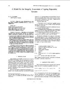
Fig. 1. Outline of 275 kV XLPE Cable Route.
FT is Fourier transform method.
March
circuits of the auxiliary circuit, and in 3 circuits of the main power cir¬ cuit of this P.S. The cable routes are given in Fig. 1. The cable has a conductor size of 600 mm2 and an insulation thick¬ ness of 29 mm. An aluminum sheath is applied for large line-to-ground fault currents in addition to the cable protection from water, fire and
Nagoya,
Japan
275 kV XLPE (cross-linked polyethylene) insulated aluminum sheathed power cable of 6200 m length and its sealing ends of 30 sets have been supplied and installed as main feeder circuits and auxiliary circuits for the Okuyahagi No. 2 pumped storage power station of the Chubu Electric Power Company Inc., Japan. This is the first use of 275 kV XLPE cable in the main circuit of a power station. Okuyahagi No. 2 Power Station, is a pumped storaged power station utilizing dams constructed along the Yahagi River in Aichi Prefecture, central part of Japan. The maximum output power of this P.S. is 780 MW. 275 kV XLPE insulated aluminum sheathed power cable is used in 2
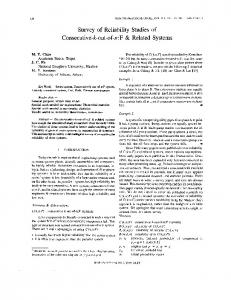
Fig. 2. 275 kV XLPE Cable. 35