Design Guideline for Microfluidic Device and Component Interfaces Editors: Henne van Heeren (enablingMNT), Tim Atkins (Blacktrace/Dolomite), Nicolas Verplanck and Christine Peponnet (CEA-LETI), Peter Hewkin (CfBI), Marko Blom and Wilfred Beusink (Micronit), Jan-Eite Bullema (TNO), Stefan Dekker (University of Twente). With contributions / suggestions and support from persons from the following organisations: APIX, Axxicon, Bronkhorst, CEA-Leti, CfBI, CMC Microsystems, Corsolution, Cytocentrics, Diagnostics Biosensors, DIBA, Dolomite, enablingMNT, EV Group, EVEON, Fluigent, IMTag, IMTEK, Invenios, IPHT, IVAM, LioniX, Memsmart, Microfluidic ChipShop, Microfluidic Consortium, Micronit, MinacNed, NIST, Philips, PhoeniX, Qmicro, SCHOTT Technical Glass Solutions, Semi, SIMTech Microfluidics Foundry, Skalene, Sony DADC, Stanford University, Stiplastics, TNO, University College London, University Twente, and many others.
Comments, suggestions and questions regarding this document can be addressed to: Henne van Heeren enablingMNT –
[email protected] 0031786300748
This work was supported by the Microfluidic Consortium and the MFManufacturing project, co-funded by grants from the UK, France and the Netherlands and the ENIAC / ECSEL Joint Undertaking. Version 1.0, December 2015
Design for Microfluidic Device and Component Interface Guidelines, version 1.0
CONTENTS 1.
Introduction ..................................................................................................................................... 3
2
Definitions around chips and connectors........................................................................................ 4
3.
Pro forma standard chip sizes and interconnections ...................................................................... 5
4.
Standard guidelines for axes and reference point .......................................................................... 7
5
6
4.1
XY axes ..................................................................................................................................... 7
4.2
Chip reference point................................................................................................................ 8
Microfluidic ports ............................................................................................................................ 9 5.1
Port pitches ............................................................................................................................. 9
5.2.
Nominal distance of the first fluidic port from the reference point ..................................... 10
5.3
Distance between two rows .................................................................................................. 10
5.4
Sizes of fluidic ports ............................................................................................................... 11
5.5
Fluidic port nomenclature ..................................................................................................... 11
Total chip thicknesses and their tolerances .................................................................................. 12 6.1
Thicknesses in use in the market........................................................................................... 12
6.2
Most popular chip combinations .......................................................................................... 13
7 Summary table of all interconnect guideline dimensions and tolerances regarding port pitches, chip thicknesses and port dimensions .................................................................................................. 14 8
9
Standard guide lines for chip formats ........................................................................................... 15 8.1
Outer chip dimensions in general ......................................................................................... 15
8.2
Microscope slide format standards ....................................................................................... 15
8.3
Credit card format ................................................................................................................. 16
8.4
Smaller chip format standards .............................................................................................. 17
Sensor / Actuator building blocks ................................................................................................. 17 9.1.
15x15 Microfluidic Building Blocks ........................................................................................ 17
9.2.
30x15 and 15x30 Microfluidic Building Blocks ...................................................................... 18
9.3.
15x45 Microfluidic Building Blocks ........................................................................................ 20
9.4.
Sensor / Actuator Microfluidic Building Block with one inlet and one outlet....................... 21
10 Edge Connectors............................................................................................................................ 23 10.1
Reference lines ...................................................................................................................... 23
10.2
Ensuring leak free connections to a chip with tubes............................................................ 23
10.3
Overview of chip stacks ........................................................................................................ 23
11 Standard guidelines for operational conditions / application classes .......................................... 24 12 And Finally ..................................................................................................................................... 26 2
Design for Microfluidic Device and Component Interface Guidelines, version 1.0
1. Introduction Context The goal of this document is to facilitate the process of designing new microfluidic sensors, actuators, connectors etc. by providing guidelines for the seamless integration with other microfluidic components and systems. This will overcome the challenge that the process of moving from a research prototype device to a production device takes too long and is too expensive. This is the case for a wide variety of materials and manufacturing processes. An important part of the challenge is that one often is designing without a clear guideline what the most appropriate method is to integrate it into a system or connect it to other devices. The flip side of the same argument is that potential users are often frustrated when components and systems presented to them are difficult, inappropriate or even impossible to interconnect with or integrate into their systems. Objectives of this paper This White Paper is an attempt to improve the situation. It is made available for free to developers and researchers around the world who are contemplating the creation of prototype devices containing microfluidics. Its purpose is to present developers a standard by which they will improve the chances of their device will be accepted by the marker / fits to other products. Positioning of this paper This paper is “application agnostic” – it is be relevant to people working in: Diagnostics, High Throughput Screening, Sample Preparation, Genomics, PCR, Circulating Tumour Cells, Regenerative Medicine, Flow Chemistry, Environmental, Food and Homeland Security Sensing... and beyond! This paper is also “materials agnostic” – we recognise that microfluidic devices can be realised in PDMS, PMMA, COC, Polycarbonate, Glass, Silicon, Metal and Paper as different players specialize in / have a preference for different materials. Furthermore this paper is “manufacturing process agnostic” – recognising again that processes can by company specific. Our vision is that newcomers to the microfluidics market – and companies that want to expand their product portfolio – will look at the relevant guidelines and design according to them. The process to create the products based on these designs will not be described or discussed in this paper. Using these design guidelines will be helpful for both user and supplier by ensuring plug and play interconnections. It is intended that this will be a “living document” updated regularly and the authors are keen on feedback regarding how the document might be improved. Note: This document does not guarantee IP freedom to operate! There is a complex landscape of patents around microfluidics devices so it is up to you to check whether you need a licence! The chosen approach concerning the guidelines towards connection/interfacing is to provide the minimum guidelines needed for interoperability, leaving open which materials to be used, what targeted applications and what connections types. We focused on keeping the guidelines simple, 3
Design for Microfluidic Device and Component Interface Guidelines, version 1.0 understandable by all and implementable by the product manufacturers as well as by the research labs. These guidelines are considered as a first essential step but certainly not an end point.
2 Definitions around chips and connectors Connection the microfluidics on a chip or substrate to the outer world is less straightforward than many may think. Often this involves connecting manually channel by channel; a laborious activity and often leading to malfunction. This can be approved by using standardized(multiport) connectors. to enable these, agreements have to be made about the dimensions of the chips and the positions of the ports. As this industry lacks a common language even the discussion itself is complicated. In order to clarify this, a few definitions will be given below. Also the area where our guidelines apply will be described. We have considered two parts particularly important for interoperability: the chip and the connector. The chip is a flat microfluidic device. Important are its format and the position of the fluidic inlets and outlets. Our guidelines will specify at least:
The chip format The inlet /outlet port localization
The connector is defined by two sides; the side connected to the chip and the other side that is left open and can be connected to a tube, an instrument, a fluidic circuit board, another chip, etc… Although one can easily represent a chip, it is much less true for the connector which is important to consider in a very broad way. Indeed in establishing these guidelines, we considered as connector not only typical connectors such as those sold by Dolomite, Micronit and others, but also the possibility to use other types of assembly methods such as adhesives (double face tape, glue..), O-rings with a clamping system or even the often used mini-Luers. Not defining completely the connectors but only the side connected to the chip gives a huge freedom to operate, independently of the chip material or the chip to chip assembly method. However, defining only the geometry (port location, and foot print) is still a great achievement since it enables interoperability. By defining only the chip geometry we avoid all the chip to chip, chip to fluidic circuit board, chip to outer world discussions, simplifying the problem to the chip and to the chip side of the connector. This simplicity enables a large number of users and manufacturers to consider using these guidelines. In order to better clarify chip topology we have agreed on the following terminologies represented in Figure 1:
Top or Bottom connections (ToB connections) Edge connections
4
Design for Microfluidic Device and Component Interface Guidelines, version 1.0
Figure 1: Schematics showing top side (left) and edge (right) connections.
Figure 2 defines the nomenclature of the top and bottom chip sides as well as the left right upper and lower edges.
Upper edge Left edge Bottom side Lower edge
Right edge
Figure 2: Schematics showing top and bottom side and edge of the chips.
3. Pro forma standard chip sizes and interconnections Although many different chip sizes are being used and can be used for microfluidics, for several reasons it might be advisable to adhere to certain chip sizes that are commonly used and supported by the supply chain. The analytical industry is using microtiter plates with standardized dimensions. (See: ANSI/SBS 4-2004). Based on this specification microfluidic chips are offered which have the same outer dimensions. When this chip size is used for microfluidics, the microfluidic connections are mostly miniLuers, placed on the borders of the chip with a pitch of 4.5 mm (or multiples of 4.5 mm) according to the positions of the outer wells of the standard layout. See Figure 3:
5
Design for Microfluidic Device and Component Interface Guidelines, version 1.0
Figure 3: Layout of a microtiter plate (Courtesy ANSI/SBS 4-2004).
Another standard chip size often used is the microscope slide format. There is some variation in dimensions of those slides, but it seems that the industry is slowly heading towards 75 * 25 mm size, although slightly larger slides (3 * 1 inch) are still being sold. We strongly advice to use SI unit in microfluidics where possible. There are two options to connect tubes to these slides: In the case of micromoulded chips, miniLuer interconnects at one or both of the long sides of the chip are the standard (see next Figure).
Figure 4: Layout of microscope slide commonly used in microfluidics with miniLuer interconnect positions
Although often used, the format above show several disadvantages, especially when one want to use multiport connectors, connectors with less dead volume or when one want to use smaller chips. Therefor the following paragraphs will present a more advanced set of standard configurations, containing optimized standard chip dimensions and positions of microfluidic ports.
6
Design for Microfluidic Device and Component Interface Guidelines, version 1.0
4. Standard guidelines for axes and reference point The objective of this part of the design guide is to provide a coherent system of reference axes used to describe positions on the chips.
4.1 XY axes Rectangular chips The naming of the chip defines the position of the XY axes. For instance a 15*30 mm chip has the X axes along the 15 mm side. The chip is then positioned with the X axis pointing from left to right. The Y axis is on the left of the viewer. The reference point is then on the top left of the chip1 (see next Figure).
Figure 5: 15*30 mm chip with axes and reference point.
A 30*15 mm chip has the X axis along the 30 mm side. The Y axis is again on the left and the reference point on the top left corner. (See Figure 6.)
Figure 6: 30*15 mm chip with axes and reference point.
As a preference one should chose the naming (and with that the X axis) in such a way that (most of) the microfluidic connections are on the side of the X axis.
1
For details regarding the reference point see next section.
7
Design for Microfluidic Device and Component Interface Guidelines, version 1.0 Square chips For square chips, the positioning of the XY axis is more arbitrary, but again the preference is that (most of) the connections are near the X axis. If that would lead to two different options due to asymmetric placement of the microfluidic ports, one should choose the one with most of the ports near the reference point (See Figure 7).
Figure 7: Preferred positioning of XY axes and reference point for square chips.
4.2 Chip reference point The reference point is the point where the two sides, named X and Y axes, cross.
Figure 8: Position of reference point determined by the two axes.
When a chip has rounded corners, as it is often the case with injection moulding, the crossing planes of the two sides of the chip, will be used as the reference point (Figure 9). 8
Design for Microfluidic Device and Component Interface Guidelines, version 1.0
Figure 9: The position of the reference point at the crossing planes (A and B) of the two sides of the chip in presence of rounded corners.
If needed, in the case of symmetrical chips for example, the reference point might be clearly marked. If this is the case, a preferred option would be to locate identification markers on the left side of the chip in an index area. This is analogous to identifying or alignment markers in electronics (sometimes also called fiducials). Several Identifying Markers can be used:
Painted or printed markers are recommended when a simple orientation check of the chip is needed. A corner cut or notch can be considered if this is needed for the assembly process.
5 Microfluidic ports This section describes the available options for positioning the microfluidic ports on a chip, it size and the coding of the port position. This is particularly of relevance for those that want to design chips and ToB connectors that are truly interchangeable. These positioning rules are also used for the definition of the edge connector standard. But that is not all, these also provide guidelines for those that have an interest to connect microfluidic sensors and actuators to microfluidic circuit boards. Finally it had an influence on the early discussions about very small microfluidic chips and their connections.
5.1 Port pitches This section describes the available options for positioning the microfluidic ports on a chip. Of all geometrical dimensions, the port pitch, i.e. the distance between the centres of two ports is perhaps the most important parameter. It was decided that all the proposed layouts are to be based on a 1.5 mm grid2. Not all the holes are necessarily present on the chip or connector, but all the hole positions are fixed. This 1.5 mm grid enables several configurations. The hole positioning is always established from the reference point, in order to avoid cumulative drifts. A 1.5 mm pitch was chosen for the following reasons:
Below 1.5 mm, according to manufacturers, it is at this moment not possible to have leakage free fluidic connections using the currently available multiport connection technologies. 1.5 mm is a good number to accommodate: o MiniLuers which have a 4.5 mm pitch widely used in microfluidics. o Microtiter plate well spacing for reservoirs filling by a multi pipette for example.
2
In the future this nominal value may be extended to a smaller one (0.75 mm instead of 1.5 mm). One of the reasons will be to open a route towards miniaturization.
9
Design for Microfluidic Device and Component Interface Guidelines, version 1.0
Reference Point 3mm
p
p
p
p
p
p
D
3
Pitch is n*1.5 mm from center to center on the x axis.
Figure 10: Top view of ToB connections showing the position of the row of hole at a distance of centre to centre of 1.5 mm from each other on the X axis.
There is a preference for a 3.0 mm port pitch (n=2). In the microfluidic field, 3 mm spacing is considered as state of the art for spacing between ports. For the near future chips and connectors with 1.5 mm pitches will likely become available.
5.2.Nominal distance of the first fluidic port from the reference point Nominal distance of the first hole/fluidic port from the reference point is a key guideline (3 mm, 3 mm) (Figure 11). The distance is defined from the reference point to the centre of the hole. This 3 mm distance from one side is the minimum distance for all four sides. This 3 mm distance was adopted after discussion with injection moulding manufacturers, assuring that such a distance from the edge ensured a robustness when using injection technologies.
Reference Point 3
p
p
p
D
3
Center of first hole is at (3 mm,3 mm) from reference point
Figure 11: Top view of ToB connections showing the position of the first hole at a distance of 3 mm from each side of the top left corner of the chip.
5.3 Distance between two rows Distance between two rows is a multiple of 1.5 mm (p*1.5 mm) from centre to centre on the y axis (Figure 12). Not all the rows are necessarily present on the chip or connector, but row positions are fixed. This 1.5 mm grid enables several configurations. The row positioning is always established from
10
Design for Microfluidic Device and Component Interface Guidelines, version 1.0 the reference point, in order to avoid cumulative drifts. The same reasoning was applied to the Y axis as the one used for the X axis. There is a preference for a 3.0 mm row pitch (p=2).
Figure 12: Top view of ToB connections showing the position of the rows at a distance of centre to centre of 1.5 mm from each other on the y axis.
5.4 Sizes of fluidic ports Controlling hole sizes for fluidic ports are important for leak free connections, reduction of dead volume and flow resistance. As hole dimensions are very much dependent on the fabrication technology it is very difficult to standardize them in total. However, minimum and maximum recommended diameters (d) of the port on the surface of the chip are:
1.5 mm pitch : 0.4 < d < 0.7 mm 3.0 mm pitch : 0.4 < d < 2.0 mm 4.5 mm pitch : 0.4 < d < 3.5 mm
Indeed, depending on the needed pressure and flow rate, diameters may need to vary in order to control pressure loss and dead volumes. However microfluidic chip and connector manufacturers considered that a distance of 1 mm between holes is required to have a good microfluidic connection. This therefore provided the upper limit of the range. An exception was made for the 1.5 mm pitch for which 0.7 mm maximum was required in order to provide a sufficient hole diameter.
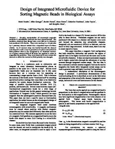
5.5 Fluidic port nomenclature Fluidic port nomenclature was proposed to simplify fluidic chips design, guidelines and instructions. We have adopted the same convention as the microtiter plate format used to identify wells: numbers for columns and letters for rows. The first possible grid position in the left corner, closest to the reference point, would be A1, the next one on the X axis with a distance of 1.5 mm will be A2. Numbers increase from left to right and letters from upper to lower edge (Figure 13).
11
Design for Microfluidic Device and Component Interface Guidelines, version 1.0 The fluidic port grid follows the standard pitch definition of 1.5 mm and can unambiguously identify port locations on a chip. The chess board type notation for fluidic ports helps to prevent mistakes between fluidic ports and electrical interconnect in a chip design where both types of interconnects are used. The generic grid is 1.5 mm pitch but the 3 mm pitch corresponds to the preferred configuration.
Figure 13: Top view of ToB connections showing fluidic port, nomenclature based on a 1.5 mm grid.
6 Total chip thicknesses and their tolerances This section deals with total chip stack thicknesses, an important feature for clamped microfluidic connectors.
6.1 Thicknesses in use in the market The discussion is complicated by the fact that there is no such thing as a standard substrate thickness as shown by the results of a recent surveys:
Figure 14: Occurrences of chip thicknesses in microfluidics.
The suppliers of glass wafers do not make us much wiser; Schott supplies 150 and 200 mm glass wafers with thicknesses between 0.1 mm and 1.1 mm. (Corning: 0.4 mm - 1.1 mm). Microscope slides are normally about 1 mm thick. Cover slides are much thinner; several versions are available with thicknesses ranging between 0.13 and 0.34 mm. The often used silicon wafers have standard thicknesses depending on their diameter as shown in the next table:
12
Design for Microfluidic Device and Component Interface Guidelines, version 1.0 Wafer size 100 mm (usually referred to as "4 inch").
Thickness (µm) 525
150 mm (usually referred to as "6 inch").
675
200 mm 300 mm
725 775
Table 1: Thicknesses of silicon wafers.
100, 150 mm and 200 mm wafers are often used to make sensors. 100 mm wafers are slowly disappearing from the market.
6.2 Most popular chip combinations To sum this up, the following table shows the most often occurring chip thicknesses and the commonly seen combinations (as discussed with several users and suppliers):
Bottom layer
Top layer 0.4 0.4 0.8 0.7 1.1 0.9 1.0 1.1 2 2.4
0.7
0.9
1.0
1.1
2
1.4 1.8 2.0 1.8
2.2 3.0
4.0
Table 2: Chip thicknesses and their combinations.
Four preferred stack thicknesses have been proposed with corresponding tolerances in relation to ToB connectors:
1 mm with +/- 0.15 mm 1.7 mm with +/- 0.22 mm 2 mm with +/- 0.2 mm 4 mm with +/- 0.4 mm
These tolerances are aimed to fit a wide range of manufacturing modes and materials used. Although easy to attain for silicon and glass, they are more challenging but not impossible for injection moulding (when higher thickness are requested). Please note, the tolerances are thus motivated from a general manufacturability perspective and not from an interfacing perspective. Not all clamping or connection solutions will therefore automatically be compatible with the given tolerances.
13
Design for Microfluidic Device and Component Interface Guidelines, version 1.0
7 Summary table of all interconnect guideline dimensions and tolerances regarding port pitches, chip thicknesses and port dimensions The relevant guidelines for ToB connectors are summarized in the table below: Parameters
Nominal value
Minimal value
Maximal value
Tolerance
Reference point : Left chip corner
0 mm
Distance of the first hole from the (3 mm, 3 reference point (3 mm, 3mm) (corner mm) edge to hole centre)
+/- 0.15 mm
Minimal distance of any hole from any side of the chip Distance between holes or port pitch n*1.5 mm (centre to centre) Rows are parallel to the chip’s x axis at a n*1.5 mm distance from ref. point of n*1.5
3 mm 1.5 mm
+/- 0.15 mm
1.5 mm
+/- 0.15 mm
Hole diameter for 1.5 mm grid
0.4 mm
0,7 mm
Hole diameter for 3 mm grid
0.4 mm
2.0 mm
Hole diameter for 4.5 mm grid
0.4 mm
3.5 mm
0.85 mm 1.58 mm 1.80 mm 3.60 mm
1.15 mm 1.92 mm 2.20 mm 4.40 mm
Total Chip Thickness Total Chip Thickness Total Chip Thickness Total Chip Thickness Tight tolerance of outer chip dimension (desired) Lower tolerance of outer chip dimension (when tight tolerance not achievable)
1 mm 1.7 mm 2 mm 4 mm
+/- 0.15 mm +/- 0.22 mm +/- 0.20 mm +/- 0.40 mm +/- 0.05 mm + 0.05 / - 0.15 mm
Table 3: Key parameters for top interconnection standardization and tolerances.
14
Design for Microfluidic Device and Component Interface Guidelines, version 1.0
8 Standard guide lines for chip formats Due to the diversity in the market, standardisation of chip formats is a difficult topic, but after analysing the situation and discussions with major players, we were able to propose here some guidelines that fit as best as possible to the demand. We added to those standard formats the position of the microfluidic ports according to the standards we developed before (see section 4).
8.1 Outer chip dimensions in general The outer chip dimensions are important for standardization. Chip formats are described in the next section. However it is important to fix the desired tolerances, while allowing for less accurate manufacturing processes. We have defined an asymmetrical tolerance for limiting oversize chips which will not fit in holders and connectors:
Maximum / desired oversize is (+ 0.05 mm) Maximum undersize is (- 0.15 mm) Preferred undersize is (- 0.05 mm)
8.2 Microscope slide format standards The official microscope slide standard3 allows all sizes in length between 76 and 74 and in width 26 and 24 mm. This will not work for affordable and reliable connectors. The two most commonly used dimensions are 75.6 x 25.4 and 75 x 25. We have chosen the slide format that fits best to the grid of 1.5 mm, which is therefore the 25.0 x 75.0 mm slide format. In order to have symmetrical connectors, we have modified the first hole location for this format: the first hole position will be at 3.5 mm4 from the long edge and 3.0 mm from the short edge. Microscope slide X1:
Figure 15: 75*25 mm microscope slide with ports having 3 mm pitches (blue); the microtiter plate well positions in a 6 mm grid are shown for reference (in orange)
3 4
Standard Microscope slide: ISO (International Organization for Standardization) 8037-1:1986. This is unfortunate deviation from the general rule, caused by the size of the slide.
15
Design for Microfluidic Device and Component Interface Guidelines, version 1.0
Microscope slide X2: Some users have a double microscope slide format, in this case 50.0 x 75.0 mm is the standard chip format. The first hole position will be 4 mm5 from the long edge and 3.0 mm from the short edge.
Figure 16: 75*50 mm microscope slide with ports having 3 mm pitches (blue); the microtiter plate well positions in a 6 mm grid are shown for reference (in orange)
8.3 Credit card format The credit card format with its well-established manufacturing production lines is often used in the industry and may be important for providers of microfluidic devices. For this reason, we have included this format which is 85.60 × 53.986 mm. To make it better compatible with the 3 mm pitch preference, we propose the following “credit card” format: 84 mm x 54 mm (see Figure 17).
Figure 17: Top view of credit card chip format showing in blue the standard fluidic ports for one row and one column.
5
This is unfortunate deviation from the general rule, caused by the size of the slide.
16
Design for Microfluidic Device and Component Interface Guidelines, version 1.0
8.4 Smaller chip format standards Although, as shown above, there are standard chip formats for the larger chip sizes, no such standard exists yet for smaller chips. That is an unfortunately situation; there is much interest to go to smaller chip sizes. For the moment we propose to use footprints that are a multiple of 15 mm in the X and Y directions. This size has been chosen because an investigation by one of the MFManufacturing partners showed that this is a format used by several companies. Furthermore, it is compatible with the 1.5 mm pitch and can accommodate a wide range of applications. That is not the end of the discussion; already there are voices that vote for chip sizes smaller than 15*15 mm.
9 Sensor / Actuator building blocks In many cases is it easier to position a sensor direct onto another component or device without using tubes for interconnections. For instance placing them on a microfluidic circuit board analogue to placing a transistor on an electronic circuit board. This part of the guidelines defines the geometries required to ensure plug and play interconnections and interoperability in such situations. Mechanical fixture can be done for instance by gluing or clamping7. We advise here generic design rules for the templates of the most common building blocks (15x15 and 15x30). We identify three types of connections: fluidic connections, pneumatic and electrical connections.
9.1.15x15 Microfluidic Building Blocks
Figure 18: Top view 15x15 Microfluidic Building Block with multiple ports.
7
The specification of the area on top of the chip needed for clamping will be specified later.
17
Design for Microfluidic Device and Component Interface Guidelines, version 1.0
Figure 19: Top view of 15x15 Microfluidic Building Block with ports centred on short edges.
Figure 20: Top view of 15x15 Microfluidic Building Block with a single centred port in D4 position.
9.2. 30x15 and 15x30 Microfluidic Building Blocks
Figure 21: Top view of a 30x15 mm building block with ports on the long side.
18
Design for Microfluidic Device and Component Interface Guidelines, version 1.0
Figure 22: Top view of a 15*30 mm building block with ports on the short side.
Figure 23: Top view of a 15*30 mm building block with centred ports.
19
Design for Microfluidic Device and Component Interface Guidelines, version 1.0
9.3. 15x45 Microfluidic Building Blocks
Figure 24: 15x45 Microfluidic Building Block with multiple ports on the short side.
Figure 25: 15x45 Microfluidic Building Block with centred ports.
20
Design for Microfluidic Device and Component Interface Guidelines, version 1.0
9.4. Sensor / Actuator Microfluidic Building Block with one inlet and one outlet
Figure 26: Sensor block layout with fluidic, electrical and pneumatic interconnections (1)
Pneumatic Valve Building Block
Port designation A1 A3 A7
Function Fluid inlet Pneumatic actuation Fluid outlet
Figure 27: Sensor block layout with fluidic, electrical and pneumatic interconnections (2).
21
Design for Microfluidic Device and Component Interface Guidelines, version 1.0
9.5.Example of the use of standardized sensor / actuator interfaces The next Figure shows an example where companies have made use of the standardized sensor / actuator layout (dimensions and port pitches). The components on the microfluidic board (they are form several suppliers), al adhere to the proposed standards discussed above.
Figure 28: Example of the use of sensor / actuator standard to create a complete functional tool (courtesy EVEON)
22
Design for Microfluidic Device and Component Interface Guidelines, version 1.0
10 Edge Connectors Some outcomes from the top connector discussion can be used for the edge connector specification: distance to edge (3 mm), port pitch (based on a grid of 1.5 mm) and chip sizes (multiples of 15*15 mm). There are however two additional dimensions to be defined: thickness of top layer and thickness of bottom layer. Besides that, the specification of the diameter of the port might be different from those of top holes. Only chip to tube connectors will be discussed, the option of an interposer (for fanning out) is not taken into account.
10.1 Reference lines All distances are given with reference to two lines:
Figure 29: Items to be specified for edge connectors8.
10.2 Ensuring leak free connections to a chip with tubes Often used small polymer tubes have an outer diameter of 0.8 mm. In order to have ample room for tolerances and leak free connection of clamped connectors, a preferred thickness of 2 mm and a minimal thickness of 1.4 mm for the total stack are recommended by experts9.
10.3 Overview of chip stacks From the discussion above and table 2 on page 13 we distinguish the following general cases: Thickness bottom layer
Corresponding tubes10 0.8 or 1.6 0.8 or 1.6‡ 0.8 or 1.6‡ 0.8 or 1.6‡ 0.8 or 1.6‡ 0.8 or 1.6‡ 0.8 or 1.6‡ 0.8 or 1.6‡ 0.8 or 1.6‡
Comment
2 +0.2 / -0.2† 1.0 +0.15 / -0.15† 0.7 +0.07 / -0.07 Includes glass with silicon 1.0 +0.15 / -0.15† 0.7 +0.07 / -0.07 Includes glass with silicon 0.4 +0.04 / -0.04 0.7 +0.07 / -0.07 Includes glass with silicon 0.4 +0.04 / -0.04 0.4 +0.04 / -0.04 Table 4: standards for edge connectors († for better alignment of tube to port and better performance, smaller A B C D E F G H I
2 +0.2 / -0.2† 2 +0.2 / -0.2† 2 +0.2 / -0.2† 1.0 +0.15 / -0.15† 1.0 +0.15 / -0.15† 1.0 +0.15 / -0.15† 0.7 +0.07 / -0.07 0.7 +0.07 / -0.07 0.4 +0.04 / -0.04
Thickness top layer
tolerances are generally recommended; ‡ ‘socket’ seal needed)
8
To ease the discussion in the rest of the document it is assumed that the thickest layer is at the bottom. In the future constructions using 0.4 mm chips is foreseen. 10 These are recommended tubesizes, other (smaller) tubes can also be used. 9
23
Design for Microfluidic Device and Component Interface Guidelines, version 1.0
11 Standard guidelines for operational conditions / application classes This part is still under discussion and is provided here as an example of how we will proceed rather than a final version of operational condition limits. We came to this point by an iterative process using surveys to check our initial assumptions. Temperature and pressure were chosen as key elements for the operating conditions while they are closely linked to the applications and have important consequences in terms of manufacturing chips or connectors. Depending on the conditions temperature or pressure, material choice will be impacted as well as the design. The first survey provided a coarse overview of the field. The proposed temperature and pressure ranges for the second survey were chosen based on the following considerations:
The temperature range 4 - 50 °C was chosen while this range is used by many suppliers of off the shelve pumps. The temperature range 0 - 100 °C is chosen to cover also applications using polymerase chain reaction (PCR) On advice of the some suppliers, who felt that the difference between 50 and 100 °C was too much, 75 °C was chosen as a upper limit too. 2 And 7 bar are maximum pressures that are quite commonly used by suppliers to specify their products. The other limits are based on the outcome of the first survey. The second and third survey provided more information about the distribution of the user over the classes. (see Figure 30)
Figure 30: Distribution of the users of microfluidics over the classes (from a survey).
24
Design for Microfluidic Device and Component Interface Guidelines, version 1.0 Based on this outcome we created a first proposal for operating classes: Classes A B C D E F
Minimum temperature (°C) 4 0 0 4 4 0
Maximum Temperature (°C) 50 75 100 50 50 100
Maximum pressure (bar) 2 2 2 7 30 7
Table 5: Proposal for application classes.
Table 5 presents only a starting point in relation to classification. Undoubtedly a more comprehensive classification scheme is envisaged, once other distinctive features like for instance flow and media used will be taken into account. It is therefore likely that other classes and sub-classes will be introduced into the scheme of things, which will be explored in follow up surveys. For example, we will explore if this classification system can be extended to cover different media used, thus taking into account if the device is designed for chemicals or biologicals. In addition, the classification system will need to take into account special devices, such as those that operate at higher pressures/temperatures than those listed in the table. For example, the classification system will need to be extended to take into account special cases such as HPLC-Chip technology, where pressures are significantly higher than those listed.
25
Design for Microfluidic Device and Component Interface Guidelines, version 1.0
12 And Finally As said, this White Paper is not a final document; it is just a reflection of the first discussions about microfluidic standards. Experienced engineers will find many other details to specify; organisations working on very lost cost disposables will stress the need for smaller chips and integration. Those interested in shorter times to market and higher reliability will stress the need for industry wide accepted validation test etc. etc.. Therefor we (and hopefully you too) will regard this as a living document. We are interested in your feedback and involvement to improve it!
We are grateful to the ENIAC /ECSEL project MicroFluidic Manufacturing and the Microfluidic Consortium that have supported this work. And thanks to many, many engineers and researchers who actively participated in the many discussions leading to this document.
To be continued ==========================================================
26