Design of a Fuzzy Logic Process Controller for Flow Applications and Implementation in Series Tanks Pilot Plant Tareq Aziz Hasan AL-Qutami, Rosdiazli Ibrahim Department of Electrical & Electronic Engineering Universiti Teknologi PETRONAS Seri Iskandar, Perak, Malaysia
[email protected],
[email protected]
Abstract— Flow control is essential in many industrial applications such as chemical reactors, heat exchangers and distillation columns. Most industrial processes exhibit nonlinearities and inherit dead time, which limit the performance of conventional PID controllers. This Project aims to design and implement Fuzzy Logic Controller (FLC) for flow control applications. The objective is to overcome problems inherited with conventional PID control scheme such as handling unpredictable disturbance, non-measurable noise as well as further improve the transient state and steady state response performance. The proposed control scheme is implemented in Flow Control and Calibration Pilot Plant. The design is done using Matlab/Simulink software package and is connected to the Pilot Plant through USB-type DAQ cards. Simulation and implementation results showed that the developed controller has less overshoot, good control performance, better disturbance handling ability, great robustness and is more flexible and intuitive to tune. It is expected that this advanced controller improves efficiency and productivity of industrial processes through proper handling of any disturbance or noise and increase the robustness of controller actions. Index Terms—PID, Fuzzy Logic control, flow rate control, process control, disturbance handing, series tanks flow process, Fuzzy Logic Controller tuning.
I. INTRODUCTION Precise measurement of flow is essential in the process industries to ensure proper rate of supply of ingredients during mixing and blending of materials and to avoid any high rate that may cause temperature or pressure to reach dangerous levels, or spilling of materials. Furthermore, Flow measurement is used in custody transfer and is essential for accounting and payment purposes [1, 2] . Flow measurement is classified into volumetric flow rate (Liters/min, ft3/s, gallons/s), mass flow rate (fluid mass per unit time like kg/h) and flow velocity (kg/h or Ib/h) [1]. The most widely used controllers in industry are PID controllers in eq. (1) because of their simple structure and satisfactory performance as long as they are properly tuned [3, 4]. (1)
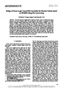
PID is a linear-type controller and hence is only efficient for a limited operating range when used to control non-linear processes[5]. But most of the industrial processes exhibit nonlinear characteristics and inherit long dead-time such as flow, PH and temperature [5, 6]. Moreover, parameters tuning is sensitive and has to be changed with changing process conditions and requires expertise in order to be tuned properly [7]. These reasons led to the development of advanced nonlinear controllers such as MPC, Fuzzy logic and Neural Networks based controllers. The objectives of this project are to design advanced controller for flow process using Fuzzy Logic principles then implement the designed strategy onto a Pilot Plant followed by comparison between current PID control strategy and the proposed advanced controller in terms of control performance and handling disturbances. Using limited experimental data to generate a reliable empirical model is a challenging task especially for MIMO and nonlinear processes. Traditionally, statistical models are developed using these experimental data. However it is still hard to choose the most appropriate model structure and parameters. Mathematical modeling for some processes like flow is not easy and therefore model based control is not possible [8]. It seems that new methodologies for efficient control and modeling are required. This is where Fuzzy Logic and Neural Networks come in [7]. II. FUZZY LOGIC Fuzzy Logic is a mathematical system that can deal with uncertain and ambiguous information which is complex to calculate by means of conventional mathematics [8]. Fuzzy Logic uses Fuzzy sets in continuous interval [0, 1] rather than two-valued logic (0, 1) or crisp set. Fig. 1. shows the general configuration of Fuzzy Logic system. Fuzzification interface converts crisp input to a linguistic variable using membership functions while Defuzzification interface converts the fuzzy output into crisp number using membership functions.
Common Defuzzification methods are Centroid of Area, Mean of Maximum and Largest of Maximum.
Fig. 1. Basic configuration of Fuzzy Logic system
Rule base is set of if-then statements that represent expert’s linguistic knowledge while Decision-making unit converts Fuzzy inputs to Fuzzy outputs using the Rule Base and determines how rules are activated and combined using operators such as AND, OR, and NOT operators. Fuzzy Inference System (FIS) combines rule base and decisionmaking unit and most common FIS are Mamadani [9] and Takagi and Sugeno[10]Fuzzy Inference Systems. General FLC block diagram is shown in Fig. 2. The inputs to most of FLCs are the error and error rate of change; the outputs go through scaling functions and then fed to the final element (e.g. Control Valve).
continuously stirred tank reactor. Prior knowledge divides the process into Fuzzy regions that are used to propose Fuzzy control scheme, besides secondary variable is used to identify the operating region. As well as several other Fuzzy controllers were developed for several processes involving disturbance, nonlinearity and long dead-time and proved to have improvements over the conventional controller. Hybrid Fuzzy-PID controllers were developed for several processes such as polymerization process which was proven to be more reliable than conventional PID, batch time and the energy consumption were reduced for batch distillation column process [15]. Simple tuning mechanisms for PID controllers were developed using Fuzzy logic for SISO and MIMO systems and were tested on coupled double tank plant where water level is the controlled variable and results showed better performance and rejection of disturbance associated with tank nonlinearity than conventional PID [16]. Lastly, a Fuzzy Logic incremental-type controller was implemented to regulate flow rate between two water tanks using 9 MFs 2 inputs Mamadani FIS [17]. IV. FUZZY LOGIC CONTROLLER STRUCTURE Different structures of FLCs have been developed, most common ones are: 1. FPD Controller: Fuzzy PD controller in Fig. 3. has advantage of less overshoot due to the use of derivative term however it is sensitive to noise and an abrupt change of the reference causing a derivative kick [18].
Fig. 2. Fuzzy Logic Controller block diagram
III. FUZZY LOGIC IN PROCESS CONTROL Fuzzy Logic principles have been used in industry and have managed to overcome problems inherited in conventional PID controllers. For example NOX reduction in a power plant and plasma-etching are non-linear processes that were modeled by Lou and Huang [8] using Fuzzy logic through limited experimental data. Takagi and Sugeno who developed Fuzzy controllers for water cleaning process and a converter in a steal-making process which solved the decomposition and realization problems of the controllers [11]. Another application is in boiler systems of power plants where level control of water inside drum is crucial, and PID control fails in the presence of process disturbance while Fuzzy logic controller performed better in disturbance handling [3]. Another Fuzzy controller was also developed for temperature control in oil steam distillation and results achieved were better than PID in terms of step point tracking [12]. A Type-2 Fuzzy controller was developed for aerobic alcoholic fermentation nonlinear bioprocess characterized by parameter uncertainty proved to reduce the negative effects of system parameters with a minimum computational load [13]. a multiregional FLC was proposed by Qin and Borders [14] for control of nonlinear processes such as pH titration in
Fig. 3. FPD controller
2. FPI (Incremental) Controller: Fuzzy PI controller or incremental controller in Fig. 4. will ensure zero steady state error. The change in control signal cu is added to the current control signal, A disadvantage is that it cannot include Daction well [4, 18].
Fig. 4. Incremental controller
3. FPD+I Controller: Fuzzy PD+I controller in Fig. 5. is a three input controller that combines FPD controller with I controller. The integral error is computed as (2) It offers all advantages of PID; nonetheless it inherits its drawbacks of integration windup and derivative term kick.
Fig. 5. FPD+I controller Fig. 8. Proposed Fuzzy Logic controller structure
V. METHODOLOGY
Fig. 6. Project Flowchart
A. Tools and Software Required
Computer. 2 of USB-1208FS cards or 1 USB-1208FSPLUS card. Simulink/MATLAB software package. PcA SimExpert Flow Control and Calibration Process Mobile Pilot Plant. 250 ohm resistors to convert 4-20mA into 1-5V.
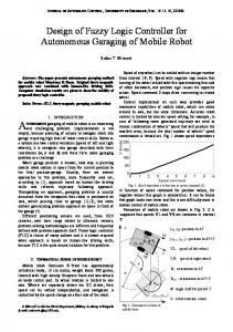
The Fuzzy PD part will ensure faster reaction and dampen the oscillations and its effect can be controlled through GU gain that controls the amount of derivative action contribution to the output. A Proportional gain that is dependent on the error has been added and it can be used to increase the initial kick of the controller however increasing this value may lead to harder tuning of other parameters and bigger overshoots. B. Fuzzy Inference System (FIS) and Membership Functions Both Sugeno-Takagi FIS and Mamadani FIS were considered initially however Sugeno-Takagi type FIS has been chosen for this controller since it is computationally efficient and can be optimized during implementation. Fig. 9. and Fig. 10. show the membership function of input variables. NB 1
Degree of membership
Flow of project activities is shown in Fig. 6.
NM
NS
ZE
PS
PM
PB
-20
-10
0 E
10
20
30
0.8
0.6
0.4
0.2
0
General setup Block diagram is shown in Fig. 7.
-30
Fig. 9. Membership functions for input E
Degree of membership
NB 1
NM
NS
ZE
PS
PM
PB
-20
-10
0 CE
10
20
30
0.8
0.6
0.4
0.2
0
Fig. 7. Implementation Setup diagram
-30
Fig. 10. Membership functions for input CE
VI. FUZZY LOGIC CONTROLLER DESIGN A. Structure The Fuzzy Logic Controller (FLC) for this project has Fuzzy PD +Fuzzy PI structure shown in Fig. 8. and equation 3. The inputs are Error (E) and Derivative of error (CE) while the output of FIS is change in control action (CU). GE and GCE are input gains used to map input ranges to the range of FIS. The Fuzzy PI part (incremental controller) accumulates CU and ensures zero steady state error; it has GCU gain to control the accumulation rate and it is dependent on the process dead time and rise time.
Error and Change of Error have 7 Gaussian-type MFs and ranges are set to [-30 30], the Pilot Plant operating limits. The output membership functions for the output are discrete values rather than fuzzy membership functions. Output membership Functions are: Positive Big (PB), Positive Medium (PM), Positive Small (PS), Zero (ZE), Negative Small (NS), Negative Medium (NM), Negative Big(NB). All outputs are distributed equally in the range of [-0.4 0.4]. C. FIS Rules ABLE I. and TABLE II. show the 45 FIS rules developed for T the Fuzzy Logic Controller and the different operating regions, they are based on the behaviors of PID controller.
TABLE I. FLC RULES AND RELATIONSHIP BETWEEN INPUTS AND OUTPUT
NB NB NB NM NM NS PS PB
TABLE II.
NM NB NB NS NS NS PS PB
NS NB NM NS ZE ZE PM PB
ZE NB NM NS ZE PS PM PB
PS NB NM ZE ZE PS PM PB
PM NB NS PS PS PS PB PB
PB NB NS PS PM PM PB PB
OPERATING REGIONS AND APPROPRIATE ACTIONS
I: Starting up, response to the Set Point change II: Error is not changing, change output accordingly III: Moving along, Maintain output IV: getting worse, reverse output somewhat.
SP PID FLC
20
flow rate (l/min)
E/CE NB NM NS ZE PS PM PB
If we change the tuning to have a more aggressive response in the expense of overshoot in order to see how the controller will handle overshoot we get the responses shown in Fig. 13. and Fig. 14. due to step point change and random steps respectively. We can observe that FLC still has superior performance, faster settling time and less overshoot than PID.
15
10
V: Error changing very fast, adjust output a bit if necessary. VI: reached equilibrium
5
0 0
VII: Error is zero but changing
100
200
300 100 samples/s
400
500
600
Fig. 13. Response of PID and FLC to step change (aggressive tuning)
VIII: Error is zero but changing insignificantly, action maintained.
SP PID FLC
40
VII. SIMULATION RESULTS Simulations were based on the FODT model in Eq. 3, a result from empirical modeling on the Pilot Plant.
flow rate (l/min)
35 30 25 20 15 10 5 0 0
ig. 11. shows the results of a step change of 20 l/min for PID F and FLC, FLC clearly performs better in both transient and steady state. Both controllers were tuned such that no overshoot happens. Fig. 12. shows response due to several random changes to ensure FLC has same performance throughout the whole range and using different step size.
1000
2000
3000 100 samples/s
4000
5000
6000
Fig. 14. Response of PID and FLC to Random steps (aggressive tuning)
We conclude from the simulation results that FLC has better performance and that is due to the nonlinearity inherited within the design and the proper handling of error rate and its influence on the change in control action. VIII. EXPERIMENTAL RESULTS
SP PID FLC
flow rate (l/min)
20
15
10
This section aims to validate the controller design through real system implementation in the Pilot Plant which is two interacting series tanks with the objective of controlling the fluid transfer rate between the two tanks. Results are shown in Fig. 15. and Fig. 16.
5 SP PID FLC
40
100
200
300 100 samples/s
400
500
600
Fig. 11. Response of PID and FLC to step change 40
SP PID FLC
35 flow rate (l/min)
30
flow rate (l/min)
0 0
35
30
25
25
1000
20 15
1200
1300 1400 100 samples/s
1500
Fig. 15. Response of PID and FLC to step change
10 5 0 0
1100
1000
2000
3000 100 samples/s
4000
5000
Fig. 12. Response of PID and FLC due to random steps
1600
1700
SP PID FLC
flow rate (l/min)
40 35 30 25 20 1000
1500
2000
2500
3000 3500 100 samples/s
4000
4500
5000
5500
Fig. 16. Response of PID and FLC due to random steps
FLC has generally better tracking performance, faster rise time and settling time, less overshoot compared to PID. TABLE III. Summarize the results from both simulation and implementation. TABLE III. RESPONSE CHARACTERISTICS FOR CONTROLLERS Mode Parameter/Controller Settling Time (s) Overshoot (%)
Simulation PID FLC 3.9 1.9 0.7 0.5 0
Rise Time (s)
Implementation PID FLC 3.8 1.4 0.7 0.6
0
12.4
2.2
IX. DISTURBANCE HANDLING In this segment controller performance is examined when subjected to sudden disturbance using the manual valves in the pilot plant. Changing Hand Valves 101 and 121 to 20% opening will reduce the flow rate (MV), then waiting until the controller adjusts the Control Valve to make PV equal to MV, then changing both Valves back to 100% as fast as possible will create a disturbance in MV that controller has to handle. Fig. 17. shows the results. FLC disturbance response MV
37
PV
PV(l/min), MV(%)
36 35 34 33 32
30 1500
2000
2500
3000 3500 4000 100 Samples/sec PID disturbance response
4500
5000
5500
PV MV
PV(l/min), MV(%)
36
34
32
30 1000
Tuning stage usually requires experience and some intuition; however there are some guidelines that can be followed in order to accelerate tuning: 1. All gains are initialized to zero. 2. Identify the range of the system and modify GE to scale to the range of FIS universe [-30 30], the maximum E must not go beyond limit of universe, i.e. |Emax*GE|=|Universemax|. 3. Increment GCU until you have zero steady state error and the response starts to oscillate, good initial value is Ki/1.2 from conventional PID gains. 4. Increment GCE until the oscillation is removed or the response starts to undershoot, good initial value is Kp/2 from conventional PID gains. 5. Alternate between incrementing GCU and GCE until there is overshoot followed by undershoot. 6. Alternate between incrementing GU and decrementing GCE until you get the best rise time, minimum overshoot and no undershoot. 7. To improve the performance further, increment GEU slightly to get better rise time, and then repeat steps 4-6 to remove any overshoots but this time consider either incrementing or decrementing each gain depending on the response, this is done through observation of the effect of each gain and intuition. XI. CONCLUSION Fuzzy Logic-based controllers exhibit far better control performance and stability than conventional PID controllers, they are flexible and can handle any sudden changes or disturbances on the system. It is expected that the efficiency of the process and ability to handle any disturbances will be increased dramatically. The designed system can then be transferred into real industrial processes through the use of modern PLCs which support Fuzzy Logic; such PLCs are available nowadays from different manufacturers such as Siemens and Omron. Furthermore, Fuzzy Logic Controller can perform well despite presence of process nonlinearities, operation variability and measurements noise. XII. FUTURE WORK
31
1000
X. CONTROLLERS TUNING PROCEDURE
1500
2000
2500
3000 3500 100 Samples/sec
4000
4500
5000
5500
Fig. 17. PID and FLC Controllers disturbance response
FLC shows superior handling of disturbance both in terms of recovery time (5.8s) and undershoot (1.3%) while PID takes 14.8s to recover and has 2.5% undershoot percentage.
It is recommended to expand current work and develop a level controller that is cascaded with the flow controller and test how it performs in the cascade system. Furthermore, an investigation is required to develop a comprehensive and clear procedure to tune FLC; this will guarantee optimum performance and stability of the controller. Another recommendation is to take this project to the next phase, which is implementation in industrial PLC or DCS system and test whether it will still have the same performance and explore ways of optimization to implement the controller with minimum resources. Last recommendation is to expand the designed controller into other processes such as temperature and pressure and test whether this controller can be used to control these processes with minimum changes to the structure or FIS rules.
REFERENCES [1] [2]
[3]
[4]
[5]
[6]
[7]
[8]
[9]
T. L. M. Bartelt, Instrumentation and process control vol. 1: Thomson Delmar learning, 2007. A. K. Pandey, "Low Cost Sensor for Low Flow-Rate Measurement," in Sensors for Industry Conference, 2005, 2005, pp. 6-8. H. F. VanLandingham and N. D. Tripathi, "Knowledgebased adaptive fuzzy control of drum level in a boiler system," in Southcon/96. Conference Record, 1996, pp. 454-459. K. J. Astrom. Control System Design [Online]. Available: http://www.cds.caltech.edu/~murray/courses/cds101/fa0 2/caltech/astrom.html G. Zaidner, S. Korotkin, E. Shteimberg, A. Ellenbogen, M. Arad, and Y. Cohen, "Non linear PID and its application in process control," in Electrical and Electronics Engineers in Israel (IEEEI), 2010 IEEE 26th Convention of, 2010, pp. 000574-000577. M. Yukitomo, Y. Baba, T. Shigemasa, M. Ogawa, K. Akamatsu, and S. Amano, "A model driven PID control system and its application to chemical processes," in SICE 2002. Proceedings of the 41st SICE Annual Conference, 2002, pp. 2656-2660 vol.4. Z. Dingxue and X. Zhen, "Fuzzy PID control in the process control," in Instrumentation & Measurement, Sensor Network and Automation (IMSNA), 2012 International Symposium on, 2012, pp. 587-591. H. H. Lou and Y. L. Huang, "Fuzzy-logic-based process modeling using limited experimental data," Engineering Applications of Artificial Intelligence, vol. 13, pp. 121-135, 4/1/ 2000. E. H. Mamdani and S. Assilian, "An Experiment in Linguistic Synthesis with a Fuzzy Logic Controller," International Journal of Human-Computer Studies, vol. 51, pp. 135-147, 8// 1999.
[10]
[11]
[12]
[13]
[14]
[15]
[16]
[17]
[18]
M. Sugeno, "Fuzzy measures and fuzzy integrals: a survey," Fuzzy Automata and Decision Processes, , pp. 89-102, 1997. T. Takagi and M. Sugeno, "Fuzzy identification of systems and its applications to modeling and control," Systems, Man and Cybernetics, IEEE Transactions on, vol. SMC-15, pp. 116-132, 1985. N. N. Mohammad, N. Kasuan, M. H. F. Rahiman, and M. N. Taib, "Steam temperature control using fuzzy logic for steam distillation essential oil extraction process," in Control and System Graduate Research Colloquium (ICSGRC), 2011 IEEE, 2011, pp. 53-58. C. Bartolomeo and G. Mose, "Type-2 fuzzy control of a bioreactor," in Intelligent Computing and Intelligent Systems, 2009. ICIS 2009. IEEE International Conference on, 2009, pp. 700-704. S. J. Qin and G. Borders, "A multiregion fuzzy logic controller for nonlinear process control," Fuzzy Systems, IEEE Transactions on, vol. 2, pp. 74-81, 1994. A. M. F. Fileti, A. J. B. Antunes, F. V. Silva, V. Silveira Jr, and J. A. F. R. Pereira, "Experimental investigations on fuzzy logic for process control," Control Engineering Practice, vol. 15, pp. 1149-1160, 9// 2007. M. B. B. Pinto, J. G. R. Mota, and O. M. Almeida, "PID selfadjustable fuzzy logic MIMO case: Method and application," in Industry Applications (INDUSCON), 2010 9th IEEE/IAS International Conference on, 2010, pp. 1-6. E. Pathmanathan and R. Ibrahim, "Development and implementation of Fuzzy Logic Controller for Flow Control Application," in Intelligent and Advanced Systems (ICIAS), 2010 International Conference on, 2010, pp. 1-6. J. Jantzen, "Tuning Of Fuzzy PID Controllers," Technical University of Denmark, Lyngby, DENMARK 98-H 871 30 Sep 1998.