JOURNAL OF AUTOMATIC CONTROL, UNIVERSITY OF BELGRADE, VOL. 16:13-16, 2006©
Design of Fuzzy Logic Controller for Autonomous Garaging of Mobile Robot Srđan T. Mitrović
Index Terms—FLC, fuzzy magnets, garaging, mobile robot
A
I. INTRODUCTION
garaging of mobile robot is an interesting and challenging problem. Implementation is not simply, because planning of actions to navigate robot into garage requiring high level of robot control skills. Robot as a system has two control variables (speed of left and right wheels), it is navigates into garage described with three coordinates (x, y and β) and these facts make garaging problem as a challenge. When garage position is known, next step is planning mobile robot motion in space from the current position to the final position-garage. Usually, there are several approaches to this problem, more frequently used are, according to [1], approach based on human-like driving skills and referent trajectory following approach. Disregarding on approach, garaging problem is usually discussed from the viewpoint that robot is positioned on lane, which passing close to garage [1]-[3], but some authors generalizing problem approach on space in front of the garage [4]. Different positioning sensors are used, from CCD cameras, over laser range meters to ultrasonic sensors; problem-solving methodologies are different and frequently defined with problem approach itself. Fuzzy logic controller (FLC) is choice of many authors and it is almost required when approach is based on human-like driving skills, because FLC is the quite natural solution for this problem. UTONOMOUS
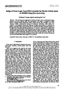
Speed of any wheel can be settled with an integer number from interval [-9, 9]. Speed with negative sign means that turning of the wheel settled with this speed moving that side of robot backward, and positive sign causes the opposite action. Speed command 0 stops drive concerning to related wheel. Control implemented on such way provides good maneuvers capabilities of mobile robot, which can rotate around its axis, but has some limitations. Accurate robot control is limited by discrete speed setting; for example, in case of following some generated trajectory we need to choose combination of wheels’ speed that will produce the smallest error, because the total number of wheels’ speed combination is limited set. Fig. 1 shows speed dependence V [mm/s]
Abstract—The paper presents autonomous garaging method for mobile robot Hemisson K-Team. Original fuzzy magnetic approach was combined with human-like driving skills. Computer simulation results are given to show the validity of proposed fuzzy logic controller.
200 150 100 50 0 0
S. Mitrović is with the Naval Department, Military Academy at Belgrade (e-mail:
[email protected]).
2
3 4 5 6 Speed command
7
8
9
Fig. 1. Speed dependence in function of speed command [5].
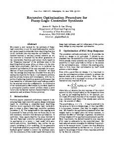
in function of speed command for positive values, for negative values this graph is symmetrical. It can be found that graph looks non-linear and this is one difficulty more in motion control of mobile robot. Parameters of mobile robot are shown in Fig. 2. It is supposed that speeds VL and VR are constants in interval T. y
(xk , yk ): position in kT VL
(xk , yk)
ψk
(xk+1 , yk+1) : position in kT+T VL: speed of left wheel
V
VR
II. KINEMATICAL MODEL OF MOBILE ROBOT
O
VR: speed of right wheel
θ
Ψk : orientation in kT R
Mobile robot Hemisson K-Team has approximately cylindrical body, 12 cm radius; weight about 200 grams, covered with high density Neoprene foam and two wheels on body central part. Its wheel rotation is limited to one axis. Wheels are separately driven via DC drives, their speed can be settled independently, and navigation is controlled by the speed change on either side of the robot.
1
ψ k+1
Ψk+1 : orientation in kT+T Θ : angle shift for period T
(x k+1 , yk+1 ) O : robot rotation centre x Fig. 2. Kinematical scheme of mobile robot.
14
MITROVIĆ S., DESIGN OF FUZZY LOGIC CONTROLLER FOR AUTONOMOUS GARAGING OF MOBILE ROBOT
Robot will keep going along the circle, radius R, with speed V: VL + VR (1) V=
for generating the next robot position, with known inputs: wheels’ speed and current position of robot.
2
and radial speed ω: ω=
III. ROBOT GARAGING WITH THE NEAREST END
VL − VR D
(2)
Angle shift for interval T is calculating as: Θ = ( VL − VR ) ⋅
T D
(3)
where D is distance between wheels. Circle radius of robot movement is calculating as: ω VL + VR D (4) R= = ⋅ , VL ≠ VR V
VL − VR 2
Orientation of robot in moment kТ+ Т is: (5)
Ψ ( k +1 ) = Ψ ( k ) + Θ
According to the Fig. 1 coordinates of circle center in moment kT may be expressed as: (6) O X = x( k ) + R ⋅ cosΨ ( k )
Because of the mobile robot symmetry, backward and forward garaging tasks are equals and this fact will be used for garaging by principle of nearest end, by what means that robot will moving backward and forward in dependence of situation, and it will finish navigation in garage with the front or back end (the nearest end). It will be shown that is possible to design only one FLC for garage task performing. A. Fuzzy „magnets“ It is defined two points: point Fp, (Fig. 3) distanced from garage front line for robot width, which lie on garage y |
(7)
Oy = y( k ) - R ⋅ sinΨ ( k )
In time kT+T coordinates of circle center can be expressed as: (8) O X = x( k +1 ) + R ⋅ cosΨ ( k +1 ) (9)
2 VL − VR D VL + VR , VL ≠ VR = y( k ) + (sinΨ ( k +1 ) - sinΨ ( k ) ) 2 VL − VR
(11)
α1 y
α2 Sg d1
With assume that, in interval [kT, kT+T], robot is moving along the circle with radius R, and circle center is fixed in this time interval, equalizing right side of (6) with (8) and (7) with (9), and inserting R from (4) give: D VL + VR (10) x( k +1 ) = x( k ) - (cosΨ ( k +1 ) - cosΨ ( k ) ) , VL ≠ VR
d2
Oy = y( k +1 ) - R ⋅ sinΨ ( k +1 )
y( k +1 )
Ψ
β
Fp Cp
Sr
Substituting Θ from (3) in (5) gives: Ψ ( k )+1 =Ψ ( k ) + ( VL − VR ) ⋅
T D
(12)
For completing the description of mobile robot kinematics, equations (10)-(12) must be complemented for case of straight line motion, when VL=VR. VL + VR (13) x( k +1 ) = x( k ) + T ⋅ ⋅ sinΨ ( k ) , VL = VR y( k +1 )
2 VL + VR = y( k ) + T ⋅ ⋅ cosΨ ( k ) , VL = VR 2
(14)
Equations (10)-(14) are complete kinematical model of mobile robot, which enables calculations of mobile robot center and orientation in moment kT+T, based on knowledge of parameters in moment kT. A. Approximate Dynamical Mode Kinematical model represents motion of mobile robot with one limitation. Namely, mobile robot is described in kinematical model without their weight, by what means inertia of robot and DC electric drives were not considered and consequence is momentary setting of ordered speeds. Because the response of robot is aperiodic function of time, previous model is translated into approximate dynamical model by adding a low pass Butterworth filter. By filtering wheels’ speed, instantaneously setting of ordered speed in simulator is prevented. The first order filter was used, with band pass of 1.225 Hz. This filter with kinematical equations is used in simulator
Fig. 3. Parameters of robot and ambient.
symmetry line Sg, and point Cp in center of the garage. Let imagine these points as a fuzzy magnets, on such way that point Fp “pulling up” the robot until it is reaches close to Fp, and point Cp “pulling up” the robot only if it is near enough to Cp. “Activities” of these points is neutralizing in garage center, and robot is stops there. For purpose of solving garaging problem, information about current distances and orientations regarding these points are required, as shown on Fig. 3. B. Suppositions It is supposed that the robot is enough distanced from garage; garage coordinates (x, y, β ) and garage size are known, and robot is positioned in front of imaginary line crossing throw garage entrance (traced with dashed line on Fig. 3. C. Fuzzy logic controller structure Designed FLC has four inputs and two outputs. Inputs are: distance from the robot to the garage center (d2), distance from the robot to the referent point in front of the garage (d1), and angles α1 и α2 (Fig. 3). As T–norm is chosen minimum method and weighted average is used as defuzzification method. If the angle α1 is equal to zero, than robot’s front end is
JOURNAL OF AUTOMATIC CONTROL, UNIVERSITY OF BELGRADE oriented to referent point Fp, and if α1 is equal to π than robot’s back end is oriented to point Fp. Analogous, if angle α2 is zero than robot’s front end is oriented to garage center, and if angle α2 is π than robot’s back end is oriented to center of the garage. Previous cases are essentially in garaging problem, because we will conduce to set angles α1 and α2 right to zero or π, depending on case. Input and output variables with corresponding membership function will be discussed in detail as follows. D. Direction (α1 and α2) Linguistics variables α1 and α2 are commonly named Direction, and described with same membership functions, which represents orientation of the robot regarding to the referent points, defined as follows: Direction {forward, forward left, forward right, backward, backward left, backward right} or in short notation: D{F, FL, FR, B, BL, BR}, as shown on Fig. 4. Forward and backward moving are symmetrical
FL
0
−π/2
−π/2 −π=π Fig. 4. Membership function of linguistic variable D
tasks, and for this reason direction is strictly divided in two groups, angles from the front side {F, FL, FR}, colored in gray on figure, and angles from the backside {B, BL, BR}. This membership functions are defined symmetrically, wherewith identical robot control is ensured regardless to that which robot’s side is closer to the garage. Universe of discourse for this linguistic variable is full circle, and from fuzzy theory viewpoint it must be limited, therefore discourse is defined in interval [-π, π], as shown on Fig. 5. Linguistic variable Direction on Fig. 5 consists of
1
B'
BL
0 −π −π+Μ −π/2
FL
F
FR
−Μ
0
Μ
π/2
E. Distances (d1 and d2) Both distances, from the robot to the garage centre and to the referent point Fp, have one membership function (Fig. 6). Linguistic variable d1 is defined with membership 1
1
far
near 0
d1[cm]
d2[cm] 0 24 30 4
200
48
function far, and linguistic variable d2 is defined with membership function near. Membership functions defined on such way are unusual, because universe of discourse is obviously not completely enveloped for both linguistics variables and just one membership function defines each linguistic variable. However, this concept is absolutely in accordance with fuzzy magnet idea.
BR B
BL
taking values π/2 or -π/2, when robot is positioned on garage symmetry line or it is far enough from the garage. If FLC is perfectly symmetrical, both outputs will be zero, without action of robot. Consequently this, one of membership functions, which limits are π/2 or -π/2, must be defined on such way to overlap adjoin function minimum for value which causes action. Only in this case we choosing which side robot will be garaged and this action solves special cases.
Fig. 6. Membership function of variables d1 and d2
FR
F
15
BR
B''
π−Μ
π
Fig. 5. Membership functions of variables α1 and α2, М=2π/9
seven membership functions: D {F, FL, FR, B’, B’’, BL, BR}, in contrary of six as shown Fig. 4, because the membership function B (Back) is divided in two sub functions B’ and B’’, as follow: B=Ѕ(B’, B’’) (15) what means that union of B’ and B’’ makes B. Because these membership functions do not overlapping, method of computing the S-norm is irrelevant. In following text will be implied that membership function B (Back) is constructed by this manner. Special cases occurring when the orientation angles
F. Speed commands Because the ordered speed must be an integer from the interval [-9, 9], this interval is accepted as universe of discourse for linguistic variables VL and VR, and they may take right these integer values. This is special case of Takagi-Sugeno controller, with constant as output function [6]. G. Rules base Rule base is constructed according to the previously notices, on such way that membership functions of input variables d1 and d2 independently activating rules, as shown in Table I. Principles of rules constructions are simple, big distances–fast turns, small distances–smaller turns, turning to the correct side according to direction, good direction–high speed. Simplified rule inspection may conduce to the incorrect conclusion that robot will not stop. Including in consideration fact that points Cm and Fm are on garage symmetry line, and if the robot is close to final position into garage than its orientation according to this points is different for π, rules with opposite action are activated and both output variables have zero as result. TABLE I INHERENCE RULES BASE
No 1 2 3 d1 far far far α1 B BL FL d2 α2 VL -8 -3 3 VR -8 -8 8
4 5 6 far far far F FR BR
8 8
8 3
-8 -3
7
8
near B -9 -9
near BL 0 -3
9
10
11
12
near near near near FL F FR BR 0 9 3 -3 3 9 0 0
16
MITROVIĆ S., DESIGN OF FUZZY LOGIC CONTROLLER FOR AUTONOMOUS GARAGING OF MOBILE ROBOT IV. SIMULATIONS RESULTS
Multiple garaging simulations are completed, respecting to the previously suppositions and post processing and preprocessing recommendations in [7], by approximate dynamical model of robot, with sampling period T=0.2s. Garage dimensions is 20cm x 24cm. Fig. 7 shows
EN d2[cm] 02 6
24 30
Fig. 8. d2 membership functions
No 13 14 15 16
d1 α1
d2 α2 S VL VR BL -2 2 EN BR EN 2 -2 FR -2 2 EN FL EN 2 -2
function extremely near (EN), as shown on Fig.8. Additional inherence rules are defined for new input (Table II), and system finally consists of five inputs and sixteen inherence rules. Multiple simulations are repeated, and it is observed that angle error is less than 2˚.
y [m]
y[m]
1
TABLE II ADDITIONAL INHERENCERULES
near
1
1
VI. CONCLUSION
0
0
0
x[m]
0
x [m]
Fig.7. Garaging simulations results
simulation results for different initial conditions, forward end of robot is marked with black solid line. Mobile robot garaging is successful, without any collision with garage walls. Distance error from the garage center is less than 2cm, but angle error in final position is about 5˚. Reason of that big angle error is degradation of significance concerning to angle α2 information when distance d2 closes to zero. V. ALGORITHM CORRECTIONS Correction of angle error requires adding one more input to the FLC, as information about difference between symmetry line of robot Sr, and garage symmetry line Sg, according to next: S=Ψ-β (16) Input S is defined as S{ FL, FR, BL, BR}, and its membership functions looks as appropriate membership functions of variable Direction (Fig. 5). To limit power of new input on nearness of garage center, linguistic variable D2 is expanded with membership
This paper shows that one complex and nonlinear problem, as mobile robot garaging, can be solved by relative noncomplex fuzzy technique. New proposed method of fuzzy magnets for garaging is successfully tested in simulations, and approximate dynamical model of Hemisson robot is used. It is shown that garaging of distanced robot is successful, for all initial conditions. According to the similar systems, for example as in [1], rule base is significantly smaller (50→16), with simultaneously speed and direction control. Difficulty is complicated fuzzy tuning, and for its determination, decomposition of algorithm in phases is proposed. REFERENCES [1] [2] [3] [4] [5] [6] [7]
S. J. Chang, “Design and implementation of fuzzy parking control methodology for car-like mobile robots”, PhD these, National Cheng Kung University, Tainan, Taiwan, R.O.C. May, 2003 A. Ohata, M. Mio, "Parking control based on nonlinear trajectory control for low speed vehicles", Proc. of IECON, Kobe, Japan, pp. 107-112, 1991 M. Wada, K. S. Yoon, H. Hashimoto, “Development of advanced parking assistance system”, IEEE Transactions on Industrial Electronics, Vol. 50, NO. 1, pp. 4-17, 2003 C. Bentalba, A. E. Hajjaji, A. Rachid, “Fuzzy parking and point IEEE stabilization: application car dynamics model”, 5th Mediterranean Conference on Control and Systems, Cyprus, 1997 A. Colot, K-Team S.A. “Hemisson user manual“, [Online]. Available: www.k-team.com J. Godjevac, “A method for the design of neuro-fuzzy controllers: an application in robot learning”, These No.1602. Ecole Polytechnique Fédérale de Lausanne, Switzerland, 1997 M. Aleksić, S. Mitrović „Design and structure of fuzzy logic controllers“, Collection of papers of the faculty of Maritime Studies at Kotor, No 21/2005