Hindawi Publishing Corporation Mathematical Problems in Engineering Volume 2013, Article ID 590861, 10 pages http://dx.doi.org/10.1155/2013/590861
Research Article Design and Implementation of Fuzzy Logic Controller for Online Computer Controlled Steering System for Navigation of a Teleoperated Agricultural Vehicle Prema Kannan,1 Senthil Kumar Natarajan,2 and Subhransu Sekhar Dash3 1
Department of Electronics and Instrumentation Engineering, SRM University, Chennai, Tamil Nadu 603 203, India Department of Electrical and Electronics Engineering, Mepco Schlenk Engineering College, Sivakasi, Tamil Nadu 626 005, India 3 Department of Electrical and Electronics Engineering, SRM University, Chennai, Tamil Nadu 603 203, India 2
Correspondence should be addressed to Prema Kannan;
[email protected] Received 12 July 2013; Revised 28 November 2013; Accepted 3 December 2013 Academic Editor: Siddhivinayak Kulkarni Copyright © 2013 Prema Kannan et al. This is an open access article distributed under the Creative Commons Attribution License, which permits unrestricted use, distribution, and reproduction in any medium, provided the original work is properly cited. This paper describes design, modeling, simulation, control, and implementation of teleoperated agricultural vehicle using intelligent technique. This vehicle can be used for ploughing, sowing, and soil moisture sensing. Online computer controlled steering system for a vehicle utilizing two independent drive wheels can be used to avoid obstacles and to improve the ability to resist external side forces. To control the steer angles of the nondriven wheels, the mathematical relationships between the drive wheel speeds and the steer angles of the nondriven wheels are used. A fuzzy logic controller is designed to change the drive wheel speeds and to achieve the desired steer angles. Online control of the agricultural vehicle is achieved from a remote place by means of Web Publishing Tool in LabVIEW. IR sensors in the vehicle are used to detect and to avoid the obstacles around. The developed steering angle control algorithm and fuzzy logic controller have been implemented in an agricultural vehicle which depicts that the vehicle performs its operation efficiently and reduces the manpower and becomes advantageous.
1. Introduction The diminishing number of agricultural wages in India is a momentous issue for Indian agriculture. Robot tractors have been introduced to replace human labors for field work and for improving work efficiency. However, robot tractor needs safety devices to ensure safe operation when it is not operated by a human. Therefore, the safety issue is an important research topic for agricultural robots when utilized on a farm [1]. Numerous studies on the automation of agricultural machines, particularly on a solution of this problem, have been carried out. Autonomous navigation and vehicle guidance, a global positioning system (GPS), a gyroscope, machine vision, and other sensors have been used in most of those studies [2–4]. Sgorbissa and Zaccaria [5] have proposed a navigation subsystem of a mobile robot which operates in human environments to carry out different tasks, such as transporting
waste in hospitals or escorting people in exhibitions. This approach integrates prior knowledge of the environment with local perceptions to carry out the given tasks efficiently and safely. They had discussed the properties of their approach and experimental results recorded during real-world experiments. Murakami et al., [6] have presented a teleoperation system for a hydrostatic transmission drive crawler type robotic vehicle. Their system was developed to satisfy the needs of various farm operations and teleoperation in unknown agricultural fields. There are two vital issues to be resolved for developing a safety device for a teleoperated agricultural vehicle; one is to detect an obstacle surrounding the vehicle and the other one is to determine the location of the obstacle. The performance of various sensors for detecting obstacles has been investigated in recent studies to improve the safety of an autonomous vehicle or assist human driving. Noguchi et al. [7] have introduced a master-slave robot system in which a
2 wireless local area network was utilized to broadcast the GPS position of a slave robot to a master robot, so that the master and slave robots could work together without collision of two robot tractors but could not detect other objects except the robot. In order to identify general obstacles, radar and stereo vision were used in some studies for automobiles [8, 9]. A laser scanner was used to identify and locate other vehicles working in the same field with the robot [10]. In addition, ultrasonic sensors [11] and a bumper switch were mounted in front of robot tractor as a safety system. In those previous studies, a laser scanner, radar, and an ultrasonic sensor were used as a range finder because these sensors can determine distance to the obstacle with a high accuracy. Knudson and Tumer [12] have evaluated reactive and learning navigation algorithms for exploration robots that avoid obstacles and reach specific destinations in limited time and with limited observations. This method uses neuroevolutionary based navigation. Neuroevolutionary approach is policy search method where control is achieved through a search across policies. This search through a population of policies allows the discovery of new and robust control strategies. Direct current (DC) motors are broadly used in conveyors, textile mills, paper mills, position control, and robotic manipulators because they are reliable for an extensive range of operating conditions and their control is fairly simple. Usually DC motors are modeled as linear systems and controlled by linear control approaches. However, most linear controllers give unsatisfactory performance due to changes in the control parameters, loading conditions, and nonlinearities introduced by the armature reaction. When these nonlinearities of the motor are known functions, then adaptive tracking control method can be used [13, 14]. If these nonlinearities of the motor are unknown, neural or fuzzy control is suitable for ensuing satisfactory performance of the closed loop system [15–18]. Senthil Kumar et al., [19] have designed an artificial neuron controller for chopper fed embedded DC drives. The designed neuron controller reduces the steady state error, overshoot, and settling time. The objective of this work is to develop a teleoperated agricultural vehicle which can be used for ploughing, sowing, and soil moisture sensing. Online computer controlled steering system for the vehicle is described and a fuzzy logic controller is designed to achieve steering control based on obstacle and boundary information of the agricultural land. The mathematical relationships between the drive wheel speeds and the steer angles of the nondriven wheels are used to calculate and control the steer angles. The developed fuzzy logic controller controls the speeds of DC motors connected with rear wheels of the agricultural vehicle to achieve the desired steer angle. Using the proposed approach, a teleoperated agricultural vehicle is controlled from a remote place. Infrared (IR) sensors are employed to detect the obstacle. The status of IR sensor helps path planning and changing the direction of the vehicle. Data transmission between the agricultural vehicle and the remote client is achieved by means of Web Publishing Tool. To accomplish this goal, a soil moisture sensor, a stepper motor, and
Mathematical Problems in Engineering
Front and rear IR sensors
Stepper motor and drive circuit
Microcontroller
DC motor and drive circuit
Speed sensors
ATMEL 89C51 Fuzzy logic controller
Solenoid valve in seed box
Modem for Internet connection
Soil moisture sensor
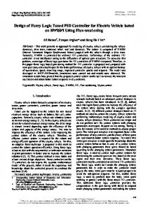
Figure 1: Hardware structure of the proposed system.
a solenoid valve are used for measuring soil moisture, to control ploughing tool and seed box open and close operation, respectively.
2. Architecture of the Proposed System Figure 1 shows the hardware structure of the proposed system. The system consists of DC motors, stepper motor, soil moisture sensor, IR sensors, and a solenoid valve. Soil moisture sensor is used to measure the moisture content of the land. The obstacles around the vehicle are detected using IR sensors. The seed box open and close operation is controlled by solenoid valve during sowing operation. Stepper motor is used to control the up and down movement of ploughing tool. The depth of ploughing can also be controlled by this stepper motor by varying its step angle. The steer angles of the nondriven wheels are controlled by two DC motors connected with the rear driven wheels of the vehicle. Based on the desired steering angle values, the desired speed values of the DC motors are calculated by using the developed algorithm. The speeds of the DC motors are controlled to the desired value by the designed fuzzy logic controller. The length and width of the agricultural land are measured. The time taken by the vehicle to travel a particular length is determined. Based on this determined time value and the length of the land, the time taken by the vehicle to reach one end of the land to the other end is calculated. The timer value is set to this calculated time value to navigate the vehicle in forward direction. For this calculated time period, the vehicle moves in forward direction, subsequently turns left, and moves in forward direction for the same period and then it turns right and moves forward. Thus by using the time taken by the vehicle to travel the length once, wheel track, and the width of the land, its navigation and steering control actions are repeated.
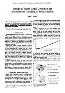
Mathematical Problems in Engineering LCD display
3 Front IR sensor
Rear IR sensor
Seeding box Solenoid Soil moisture valve sensor
Battery
Figure 2: Top view of hardware prototype of the developed teleoperated agricultural vehicle.
Ploughing tool
Rear driven wheels
Figure 3: Elevation of hardware prototype of the developed teleoperated agricultural vehicle.
3. Experimental Setup The hardware prototype set-up of the teleoperated agricultural vehicle is shown in Figures 2 and 3. The developed fuzzy logic controller and the control algorithm for ploughing action and solenoid valve were implemented using ATMEL 89C51 microcontroller. A two-way normally closed electromechanical solenoid valve is used to control the flow of seeds. The solenoid valve is energized by a normally closed relay. When the relay is energized, it comes to normally opened position. In this relay position, the solenoid valve is energized and it opens to drop the seeds. By increasing or decreasing the frequency of energization of relay circuit, the distance between the seeds can be increased or decreased. A 12 V stepper motor is used to adjust the position of ploughing tool. By controlling the stepping angle of the stepper motor, the ploughing tool position is being controlled. The navigation speed and steering angle control are achieved by two 12 V DC motors connected with two independent drive wheels. The stepper motor and DC motors are supplied by a 12 V, 7 Ah sealed lead acid battery. A soil moisture sensor is used to measure the moisture content of the soil. The measured value is displayed using LCD display.
4. Fuzzy Logic Controller General proportional integral (PI) and proportional integral derivative (PID) controllers are extensively used for motor control applications. But they do not give satisfactory results when control parameters, loading conditions, and the motor itself are changed. But fuzzy logic controller can be designed without the exact model of the system. This approach of fuzzy logic controller (FLC) design guarantees the stable operation even if there is a change in the parameters and the motor [20]. Fuzzy logic control is derived from fuzzy set theory introduced by Zadeh in 1965. In fuzzy set theory, the transition between membership and nonmembership can be gradual. Therefore, boundaries of fuzzy sets can be vague and ambiguous, making it useful for approximate systems. Fuzzy logic controller (FLC) is an attractive choice when precise mathematical formulations are not possible [21]. The designed fuzzy logic controller has two inputs and one output. The inputs are error value and change in error
Front nondriven wheels
Table 1: Rule table. Error NVB NB NM NS Z PS PM PB PVB
NVB NVB NVB NVB NVB NVB NB NM NS Z
NB NVB NVB NVB NVB NB NM NS Z PS
Change in error NM NS Z PS PM NVB NVB NVB NB NM NVB NVB NB NM NS NVB NB NM NS Z NB NM NS Z PS NM NS Z PS PM NS Z PS PM PB Z PS PM PB PVB PS PM PB PVB PVB PM PB PVB PVB PVB
PB NS Z PS PM PB PVB PVB PVB PVB
PVB Z PS PM PB PVB PVB PVB PVB PVB
and the output is duty cycle. The seven linguistic variables used for “error” and “change in error” are NVB (negative very big), NB (negative big), NM (negative medium), NS (negative small), Z (zero), PS (positive small), PM (positive medium), PB (positive big), and PVB (positive very big). The duty cycle output uses seven linguistic variables like NVB (negative very big), negative big (NB), negative medium (NM), negative small (NS), zero (Z), positive small (PS), positive medium (PM), PB (positive big), and PVB (positive very big). The rule table for the designed fuzzy logic controller is given in Table 1. From the rule table, the rules are manipulated as follows. If error is NS and change in error is PB, then output is PM. The symbolic expression of 𝑘th rule of the designed fuzzy logic controller is given as follows. If 𝑒 is 𝐿𝐸(𝑘) and Δ𝑒 is 𝐿Δ𝐸(𝑘) , then Δ𝑢 is 𝐿Δ𝑈(𝑘) ,
(1)
where 𝐿𝐸(𝑘) , 𝐿Δ𝐸(𝑘) , and 𝐿Δ𝑈(𝑘) are linguistic values from term sets of error, change in error, and change in output duty cycle, respectively. The meaning of the above defined 𝑘th rule in terms of mamdani type implication is given as a fuzzy relation 𝑅(𝑘) as follows 𝜇𝑅 (𝑘) (𝑒, Δ𝑒, Δ𝑢) = 𝜇𝐿𝐸 (𝑘) (𝑒) Λ𝜇𝐿Δ𝐸 (𝑘) (Δ𝑒) Λ𝜇𝐿Δ𝑈(𝑘) (Δ𝑢) . (2)
4
Mathematical Problems in Engineering
The overall conclusion by combining the outputs of all the fuzzy rules can be written as 𝜇𝑅 (𝑒, Δ𝑒, Δ𝑢) = 𝜇𝑅 (1) (𝑒, Δ𝑒, Δ𝑢) 𝑉𝜇𝑅 (2) (𝑒, Δ𝑒, Δ𝑢) ⋅ ⋅ ⋅ 𝑉𝜇𝑅 (𝑘) (𝑒, Δ𝑒, Δ𝑢) .
(3) Steering angle ΦL = tan−1
The value of 𝜇𝑅 (𝑘) for each value of 𝑘 is defined in (2). The crisp value of change in duty cycle is computed using centre of area method as follows: Duty cycle output = 𝑢∗ =
∫ 𝑢 ⋅ 𝜇𝑈 (𝑢) ⋅ 𝑑𝑢 ∫ 𝜇𝑈 (𝑢) ⋅ 𝑑𝑢
,
(4)
where 𝑢∗ is defuzzified duty cycle, 𝑢 is duty cycle output, and 𝜇𝑈(𝑢) is Union of the clipped control outputs.
5. Mathematical Model for Steering System Figure 4 represents kinematic model of the proposed agricultural vehicle with a primary steering system using two independently driven wheels. 𝜔L and 𝜔R are the wheel speeds of the rear left and rear right drive wheels, respectively. ΦL and ΦR are the steer angles of the front left and front right wheels, respectively. 𝑏 is the wheel base. 𝑡𝐵 is the track of the rear wheels and 𝑡𝐹 is the track of the front wheels. 𝑅 is the radius of the turning circle of the vehicle (radius of curvature) [22]. The rate of rotation of the drive axle about the centre of curvature is given by 𝜃̇ =
𝑉R 𝑉L = , 𝑅 + (𝑡𝐵 /2) 𝑅 − (𝑡𝐵 /2)
(5)
where 𝑅 is radius of the turning circle of the vehicle (radius of curvature), 𝑉L is translational velocity of the left drive wheel, 𝑉R is translational velocity of the right drive wheel, 𝑡𝐵 is the track of the rear wheels, and 𝑡𝐹 is the track of the front wheels. If longitudinal slip is considered, the translational velocities become 𝑉L = 𝑟𝜔L (1 − 𝑖L ) , 𝑉R = 𝑟𝜔R (1 − 𝑖R ) ,
(6)
where 𝑟 is radius of a drive wheel, and 𝑖 is longitudinal slip When we substitute (6) in(5) The centre of curvature 𝑟𝜔 (1 − 𝑖L ) 𝑟𝜔R (1 − 𝑖R ) 𝜃̇ = L = . 𝑅 + 𝑡𝐵 /2 𝑅 − 𝑡𝐵 /2
(7)
When the longitudinal slips are equal for left and right drive wheels, as well as equal radius for the drive wheels, then 𝜃̇ =
𝜔R 𝜔L = . 𝑅 + 𝑡𝐵 /2 𝑅 − 𝑡𝐵 /2
Equal longitudinal slips will occur where traction conditions are the same and under these conditions, slip angles will not be significant. For the front left steerable wheel,
(8)
2𝑏 (𝜔L − 𝜔R ) . 𝜔L (𝑡𝐵 + 𝑡𝐹 ) + 𝜔R (𝑡𝐵 − 𝑡𝐹 ) (9)
Similarly, for the front right steerable wheel, Steering angle ΦR = tan−1
2𝑏 (𝜔L − 𝜔R ) . 𝜔L (𝑡𝐵 − 𝑡𝐹 ) + 𝜔R (𝑡𝐵 + 𝑡𝐹 ) (10)
If 𝑡𝐵 = 𝑡𝐹 , (9) and (10) will be simplified as given in (11), and (12), respectively, 𝜔 𝑏 ΦL = tan−1 [ (1 − R )] , 𝑡 𝜔L
(11)
𝑏 𝜔 ΦR = tan−1 [ ( L − 1)] . 𝑡 𝜔R
(12)
6. Calculation of Drive Wheel Speed for Steering Control If both drive wheels turn with same speed, the robot moves in a straight line. If one wheel rotates faster than the other, the robot follows a curved path inward towards the slower wheel. If the wheels turn at equal speed, but in opposite directions, the robot spins around. Thus, steering the robot is just a matter of varying the speeds of the drive wheels. These drive wheel speeds are calculated from the steer angles ΦL and ΦR . 6.1. Calculation of Drive Wheels Speed to Turn the Vehicle Left. To turn the vehicle left, the left wheel speed should be less than the right wheel speed. Hence the left wheel speed is assigned with some low speed value and the expression for desired right wheel speed 𝜔DR is derived from the steering angle ΦL of left steerable wheel. Let 𝜔L = 1 rpm; then, (9) will be tan ΦL =
2𝑏 (1 − 𝜔R ) . (𝑡𝐵 + 𝑡𝐹 ) + 𝜔R (𝑡𝐵 − 𝑡𝐹 )
(13)
From (13), the desired right wheel speed can be written as 𝜔DR =
2𝑏 − tan ΦL (𝑡𝐵 + 𝑡𝐹 ) . 2𝑏 + tan ΦL (𝑡𝐵 − 𝑡𝐹 )
(14)
6.2. Calculation of Drive Wheels Speed to Turn the Vehicle Right. To turn the vehicle right, the right wheel speed should be less than the left wheel speed. Hence the right wheel speed is assigned with some low speed value and the expression for desired left wheel speed 𝜔DL is derived from the steering angle ΦR of right steerable wheel.
Mathematical Problems in Engineering
5
tF ΦL
ΦR
b
·
𝜃
ΦR
𝜔R
𝜔L
ΦL
R tB
Figure 4: Kinematic model of the proposed agricultural vehicle.
Start
Initialize rule table Get actual drive wheel speeds 𝜔 L and 𝜔R Get desired steer angles ΦL and ΦR ΦL = 0
Yes
ΦR = 0
No ΦL > 0
No Yes
No ΦL = ΦR
Yes
Find 𝜔DL and 𝜔DR for reverse turn
No Yes
No No ΦL > ΦR
ΦL > 0 ΦR > 0
𝜔DL and 𝜔DR for front motion
Yes
Calculate 𝜔DL and 𝜔DR for forward right turn
Yes
Calculate speeds of 𝜔DL and 𝜔DR for forward left turn from equation Compare actual 𝜔L and 𝜔R with desired 𝜔DL and 𝜔DR Fuzzify the inputs of FLC
Defuzzify the output of FLC Calculate new duty cycle
Output new duty cycle Delay
Figure 5: Flow chart of the control algorithm.
6
Mathematical Problems in Engineering
Figure 6: Block diagram of the simulated fuzzy logic control system for a teleoperated agricultural vehicle.
Figure 7: Block diagram of the simulated steering angle control system to turn the vehicle left.
Let 𝜔R = 1 rpm and then (10) will be tan ΦR =
2𝑏 (𝜔L − 1) . 𝜔L (𝑡𝐵 − 𝑡𝐹 ) + (𝑡𝐵 + 𝑡𝐹 )
7. Computer Simulation and Teleoperation (15)
From (15), the desired right wheel speed can be written as 𝜔DL =
2𝑏 + tan ΦR (𝑡𝐵 + 𝑡𝐹 ) . 2𝑏 − tan ΦR (𝑡𝐵 − 𝑡𝐹 )
(16)
The simulation of online computer controlled steering system for a teleoperated agricultural vehicle is done based on equation modeling using LabVIEW. Flow chart of the proposed control algorithm is given in Figure 5. The simulated models are shown in Figures 6, 7, and 8. The simulation of computer controlled steering system was done with a fuzzy logic controller.
Mathematical Problems in Engineering
7
Figure 8: Block diagram of the simulated steering angle control system to turn the vehicle right.
Figure 9: Configuration of server computer for remote clients using Web Publishing Tool in LabVIEW.
Online control is achieved from remote place using Web Publishing Tool in LabVIEW. This tool is used to create an HTML document and embed static or animated images of the server computer’s front panel in an HTML document as shown in Figures 9 and 10. When the HTML document is created, URL is generated as shown in Figure 11. Using this generated URL, a remote user can view and control the front panel remotely by a web browser.
8. Experimental Results The developed fuzzy logic controller and the control algorithm for ploughing action and solenoid valve were implemented using ATMEL 89C51 microcontroller. The drive wheels speeds are controlled by two 12 V DC motors. By using the proposed control algorithm, the speeds of these DC motors are controlled and measured values are plotted in the graph. The experimental response of left and right DC motors
8
Mathematical Problems in Engineering
Figure 10: Configuration of server computer for remote clients using Web Publishing Tool in LabVIEW with header and footer details.
Figure 11: URL generation by the HTML document.
when the vehicle moves in forward, reverse, left, and right directions are shown in Figures 12, 13, 14, and 15.
9. Conclusion In this paper, a teleoperated agricultural vehicle capable of performing ploughing, sowing, and soil moisture sensing
was successfully developed. Two independent drive wheels installed on the vehicle are used for motion and steering control. The developed fuzzy logic controller controls the steering angle of the teleoperated vehicle according to the desired steering angle. Using the proposed agricultural vehicle depth of ploughing and the distance between the seeds can be varied. By measuring the moisture content of
Mathematical Problems in Engineering
(a)
9
(b)
Figure 12: Graph of actual speed values of left motor and right motor when the agricultural vehicle moves in forward direction with the set speed value of 10 rpm.
(a)
(b)
Figure 13: Graph of actual speed values of left motor and right motor when the agricultural vehicle moves in reverse direction with the set speed value of 10 rpm.
(a)
(b)
Figure 14: Graph of actual speed values of left motor and right motor when the agricultural vehicle turns in left direction.
(a)
(b)
Figure 15: Graph of actual speed values of left motor and right motor when the agricultural vehicle turns in right direction.
10 the soil, the crops are watered adequately. Thus this teleoperated agricultural vehicle reduces the manpower and becomes advantageous.
References [1] N. Kondo, M. Monta, and N. Noguchi, Agricultural Robots (1), Corona, 2006. [2] J. Marchant, T. Hague, N. Tillest, and J. Sanchiz, “Research on an autonomous vehicle for precise plant treatments,” in Proceedings of the 5th International Workshop on Robotics and Automated Machinery for Bio-Productions, pp. 237–242, Gandia, Spain, 1997. [3] K. Inoue, K. Otsuka, M. Sugimoto, and N. Murakami, “Estimation of place of tractor and adaptive control method of autonomous tractor using INS and GPS,” in Proceedings of the 5th International Workshop on Robotics and Automated Machinery for Bio-Productions, pp. 27–32, Gandia, Spain, 1997. [4] T. Pilarski, M. Happold, H. Pangels, M. Ollis, K. Fitzpatrick, and A. Stentz, “The Demeter system for automated harvesting,” Autonomous Robots, vol. 13, no. 1, pp. 9–20, 2002. [5] A. Sgorbissa and R. Zaccaria, “Planning and obstacle avoidance in mobile robotics,” Robotics and Autonomous Systems, vol. 60, no. 4, pp. 628–638, 2012. [6] N. Murakami, A. Ito, J. D. Will et al., “Development of a teleoperation system for agricultural vehicles,” Computers and Electronics in Agriculture, vol. 63, no. 1, pp. 81–88, 2008. [7] N. Noguchi, J. Will, J. Reid, and Q. Zhang, “Development of a master-slave robot system for farm operations,” Computers and Electronics in Agriculture, vol. 44, no. 1, pp. 1–19, 2004. [8] Y. Fang, I. Masaki, and B. Horn, “Depth-based target segmentation for intelligent vehicles: fusion of radar and binocular stereo,” IEEE Transactions on Intelligent Transportation Systems, vol. 3, no. 3, pp. 196–202, 2002. [9] S. Wu, S. Decker, P. Chang, T. Camus, and J. Eledath, “Collision sensing by stereo vision and radar sensor fusion,” IEEE Transactions on Intelligent Transportation Systems, vol. 10, no. 4, pp. 606–614, 2009. [10] M. Kise, Q. Zhang, and N. Noguchi, “An obstacle identification algorithm for a laser range finder-based obstacle detector,” Transactions of the American Society of Agricultural Engineers, vol. 48, no. 3, pp. 1269–1278, 2005. [11] L. Guo, Q. Zhang, and S. Han, “Agricultural machinery safety alert system using ultrasonic sensors,” Journal of Agricultural Safety and Health, vol. 8, no. 4, pp. 385–396, 2002. [12] M. Knudson and K. Tumer, “Adaptive navigation for autonomous robots,” Robotics and Autonomous Systems, vol. 59, no. 6, pp. 410–420, 2011. [13] K. H. Kim, I. C. Baik, S. K. Chung, and M. J. Youn, “Robust speed control of brushless DC motor using adaptive input-output linearization technique,” IEEE Proceedings on Electric Power Applications, vol. 144, pp. 469–475, 1997. [14] M. S. Ibbini and W. S. Zakaria, “Nonlinear control of DC machines,” Electric Machines and Power Systems, vol. 24, no. 1, pp. 21–35, 1996. [15] M. A. Rahman and M. A. Hoque, “On-line adaptive artificial neural network based vector control of permanent magnet synchronous motors,” IEEE Transactions on Energy Conversion, vol. 13, no. 4, pp. 311–318, 1998. [16] A. Rubaai and R. Kotaru, “Online identification and control of a dc motor using learning adaptation of neural networks,” IEEE
Mathematical Problems in Engineering
[17] [18]
[19]
[20]
[21]
[22]
Transactions on Industry Applications, vol. 36, no. 3, pp. 935– 942, 2000. J.-H. Horng, “Neural adaptive tracking control of a DC motor,” Information Sciences, vol. 118, no. 1, pp. 1–13, 1999. A. Rubaai, D. Ricketts, and M. D. Kankam, “Development and implementation of an adaptive fuzzy-neural-network controller for brushless drives,” IEEE Transactions on Industry Applications, vol. 38, no. 2, pp. 441–447, 2002. N. Senthil Kumar, V. Sadasivam, H. M. Asan Sukriya, and S. Balakrishnan, “Design of low cost universal artificial neuron controller for chopper fed embedded DC drives,” Applied Soft Computing Journal, vol. 8, no. 4, pp. 1637–1642, 2008. N. S. Kumar, V. Sadasivam, and K. Prema, “Design and simulation of fuzzy controller for closed loop control of chopper fed embedded DC drives,” in Proceedings of the International Conference on Power System Technology (POWERCON ’04), pp. 613–617, Singapore, November 2004. D. Driankov, H. Hellendoorn, and M. Reinfrank, An Introduction to Fuzzy Control, Narosa Publishing House, New Delhi, India, 2nd edition, 2001. B. C. Besselink, “Computer controlled steering system for vehicles having two independently driven wheels,” Computers and Electronics in Agriculture, vol. 39, no. 3, pp. 209–226, 2003.
Advances in
Operations Research Hindawi Publishing Corporation http://www.hindawi.com
Volume 2014
Advances in
Decision Sciences Hindawi Publishing Corporation http://www.hindawi.com
Volume 2014
Journal of
Applied Mathematics
Algebra
Hindawi Publishing Corporation http://www.hindawi.com
Hindawi Publishing Corporation http://www.hindawi.com
Volume 2014
Journal of
Probability and Statistics Volume 2014
The Scientific World Journal Hindawi Publishing Corporation http://www.hindawi.com
Hindawi Publishing Corporation http://www.hindawi.com
Volume 2014
International Journal of
Differential Equations Hindawi Publishing Corporation http://www.hindawi.com
Volume 2014
Volume 2014
Submit your manuscripts at http://www.hindawi.com International Journal of
Advances in
Combinatorics Hindawi Publishing Corporation http://www.hindawi.com
Mathematical Physics Hindawi Publishing Corporation http://www.hindawi.com
Volume 2014
Journal of
Complex Analysis Hindawi Publishing Corporation http://www.hindawi.com
Volume 2014
International Journal of Mathematics and Mathematical Sciences
Mathematical Problems in Engineering
Journal of
Mathematics Hindawi Publishing Corporation http://www.hindawi.com
Volume 2014
Hindawi Publishing Corporation http://www.hindawi.com
Volume 2014
Volume 2014
Hindawi Publishing Corporation http://www.hindawi.com
Volume 2014
Discrete Mathematics
Journal of
Volume 2014
Hindawi Publishing Corporation http://www.hindawi.com
Discrete Dynamics in Nature and Society
Journal of
Function Spaces Hindawi Publishing Corporation http://www.hindawi.com
Abstract and Applied Analysis
Volume 2014
Hindawi Publishing Corporation http://www.hindawi.com
Volume 2014
Hindawi Publishing Corporation http://www.hindawi.com
Volume 2014
International Journal of
Journal of
Stochastic Analysis
Optimization
Hindawi Publishing Corporation http://www.hindawi.com
Hindawi Publishing Corporation http://www.hindawi.com
Volume 2014
Volume 2014