Development and Design of Mobile Robot with IP-Based Vision System Argel A. Bandala, Elmer P. Dadios De La Salle University
[email protected],
[email protected]
Abstract - Hardware, firmware and software design of a mobile robot capable of transmitting video information and receiving commands from a controlling point is presented. The hardware design is composed of a PIC18F4620 microcontroller, a UCC27525 MOSFET gate driver, XBee Series 2 OEM RF Module. Firmware design includes the reception, processing and decoding of Zigbee API packets. Based on this decoded information the microcontroller will generate signals to move the motors namely left and right motors with a corresponding direction, either clockwise of counter clockwise. The software part includes the graphical user interface which generates commands sent to the mobile robot. The images from the mobile robot are sent to the central controller. The images are then processed and a command is generated. The command is formatted in API format and then sent to the mobile robot. Testing of the system is done by experimentation. Three parameters are tested which are influenced by four parameters. Image recognition is measured while varying the distance. Also image recognition is measured while varying the luminance of the environment. The received signal level is measured while varying the distance. Lastly the accuracy of the movement of the mobile robot is also measured while varying the target position. The results showed that the distance used by the researcher has no significant effect on image recognition. The results showed also that image recognition is unaffected with the luminance of 230-1590 lumens. The mobile robot will respond in an optimum range of one meter and can respond from one to ten meters.
applications which use embedded vision systems in the robot itself. A small robot is restricted to the capability of equipping itself a vision system for the reason of power capacity and weight management. Furthermore designing a larger robot will comply with the said requirements however mobility and movement flexibility will be sacrificed. This paper introduced a mobile robot design which is capable of transmitting video information wirelessly to a base station using Internet Protocol. The base station also is capable of transmitting wirelessly digital movement commands through IEEE 802.15.4. The base station processes the video information sent by the mobile robot and generates appropriate movement and then transmits this to the mobile robot. This study developed a vision system capable of recognizing three objects and is applied to the soccer robot platform.
Index Terms – Vision System, IP based Vision, Mobile Robot, Zigbee Controlled Mobile Robot
I. INTRODUCTION The fast growing popularity of using vision system and robotics in numerous applications becomes evident nowadays [1] [2], [3]. Applications such as in military [2], manufacturing [3] medical [4], [5] and animal robotics [8], [9] started to merge the science of vision systems and robotics. However there are few
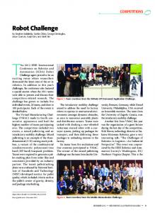
Figure 1. The General Block Diagram of the System
7c
7cm
7c
7c
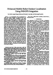
Figure 3. PCB Design of the Mobile Robot Figure 2. The Relational Block Diagram of the System II. HARDWARE BLOCK DIAGRAM The developed system is composed primarily of a base station and mobile robots as shown in figure 1. The controlling station or base station generates and sends the movement of the mobile robot which is dependent primarily on the video information sent by each mobile robot. The controlling station is composed of a desktop computer or a laptop computer. As shown in figure 2 there are two devices connected to the computer namely the zigbee receiver and the Wi-Fi router. Since the mobile robot’s vision is composed of an IP camera, it is appropriate to retrieve transmitted video information from a router. Based on these images the Graphical User Interface will generate commands which will be carried out to the zigbee transmitter. The transmitted command is then decoded by a microcontroller unit in this case a PIC18f4620. The decoded information is then translated into movements by the microcontroller which is fed to the motor driver to be executed by the motors. III. THE HARDWARE DESIGN Figure 3 shows the 3D design of the mobile robot’s printed circuit board. The board is composed primarily of Microchip’s PIC18f4629 microcontroller, UCC27524 MOSFET motor drivers, LM7805 voltage regulator. The board is powered by nine volts battery connected in a voltage regulator to provide the circuitry its maximum requirement of 5V. However the MOSFET motor drivers are directly connected to the battery to provide the required voltage of 9V to the motors.
The speed and direction of the motors are controlled by the microcontroller through pulse width modulation. Seen in figure 4 the pin outs of the motor driver used. There are two motor drivers used one for every motor. Vdd is supplied with 9V of power. ENA and ENB are enable pins which are shorted and connected to a PWM pin of the microcontroller. OUTA and OUTB pins are connected individually to the two terminals of the motor. INA and INB are input pins of the motor driver which is connected to a general input output pin of the microcontroller, one for each input pin. Providing a logic value of 1 in one of the input pins and logic value of 0 to the other input pin will generate movement to the motor provided that the enable pins is supplied with a logic value of 1. Meanwhile reversing the logic values from the previous set up will reverse the rotation of the motor with a supply of logic 1 on the enable pins. Delivering the same logic value regardless of the supply logic value to the enable pins will halt the rotation of the motors. Movement controls is further discussed in [10]. Since the enable pins of the motor driver serves as a switch for each output pins, the system make use of the PWM technic to control the speed of rotation of the motors. Controlling the speed of the motors will enable the mobile robot to turn either on left or right side.
Figure 4. Pin Assignments of the Motor Driver
Table 1. Zigbee API Packet Format
4cm
3cm
3cm
Figure 5. PCB Design of the Zigbee Daughter Board (Mobot side) The logic values in the input pines will dictate the direction of rotation of the motors and providing a value of 1 at the enable pin, the motor will rotate at full speed. To regulate the speed of rotation PWM is used by alternately varying the value of the enable pin from logic 1 to logic 0. The length of logic 1 before changing to logic 0 and logic 0 to logic 1 will dictate the speed of rotation. Decreasing the amount of time of supplying logic 1 and increasing the amount of time supplying logic 0 at the enable pin will decrease the speed of rotation. On the other hand reversing the said procedure will increase the speed of the motors’ rotation.
Xbee zigbee modules are oriented with 20 pins which includes VDD, GND, and other peripheral pins. In this study, the researchers used 4 pins which is oriented in the zigbee daughter board. These pins are VDD, GND, RX and TX. RX and TX are the receive and transmit pins respectively. These pins utilize UART communication standards.
Figure 5 displays the 3D view of the PCB for zigbee interface to the mobile robot. Since the logic level of the zigbee used for wireless transmission is different from the logic level of the microcontroller, a logic level converter of 3.3V to 5V and vice versa is required. This daughter board is equipped of the said circuitry and also this board contains the AZ117 3.3V voltage regulator which supplies the zigbee’s VDD.
The researchers used the Application Programming Interface (API) format of packets transmitted in this study. The information sent by the controlling station to the mobile robot are ASCII characters in which a character signifies the direction of movement of the mobile robot. However this information is encapsulated and formatted in a packet. The character in hex form is attached with other informations which is in the syntax presented in table 1. 64-Bit Destination Address is the 8-bit address of the destination of the message. This address is unique for every zigbee module used and cannot be altered for every device. Data is 2-bit information in length and expandable up to 8 bits. For this study, there are three basic information needed to control the robot. Forward, backward, left, right are the commands transmitted signified by four character strings. FR for forward, BW for backward, LT for left and RT for right. Each command is composed of two characters which is represented by a byte per character. This is the reason why data length is 2 bits.
IV. ZIGBEE COMMUNICATION DESIGN
V. THE GRAPHICAL USER INTERFACE
Zigbee commonly known as IEEE 802.15.4 is the wireless standard adopted by the study. Since the commands from the controlling station must be wireless the researchers decided to use digital wireless communication provided by the zigbee. A sample of zigbee module is presented in figure 6.
Figure 6. Xbee Series 2 OEM RF Module
A. The GUI Design Figure 7 shows the design of the graphical user interface for the controlling station. The upper portion is the tab in which video information is from each mobile robot is displayed this figure shows two online mobile robots. This control panel can accommodate up to but not restricted to three videos and mobile robots. The upper portion is the tab in which the administrative part of the system is set. The upper set of text boxes are the link of the video to display, the username and password of the IP camera that feeds the video.
Figure 9. Raw and Processed Image
Figure 7. The Graphical User Interface Design The values of these parameters are configured in the IP camera. The lower portion is the calibration inputs. This is the part where the value for hue, saturation and luminance of a certain goal is set. Figure 8 is the flowchart of the program embedded in the graphical user interface. The process determines whether if the target is on site of the mobile robot, if not, the mobile robot will rotate until the target is on site. However if the target is on site, the mobile robot will align itself to the target until the target is on the center. After this the mobile robot will then move forward while constantly checking if the target is in the center of the image. If not, the mobile robot will realign its position to the target and forward again. B. Recognition of Image
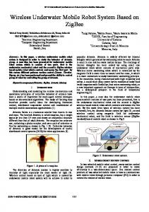
VI. EXPERIMENT RESULTS Figure 10 shows the characteristic of the signal strength of the transmission of commands using zigbee with respect to distance. Since the designed system is prospected to operate in a soccer robot field the covered distance receives ample strength to accurately transmit commands from the controlling station. Figure 11 describes the summary of results of varying the light intensity in detecting or recognizing a target image. With a low luminance, the number of detected pixels is low. However increasing the luminance at 230 lumens, the number of recognized pixels increases. Also, increasing the luminance at certain levels will cause the number of detected pixels to decrease. To conclude, a certain range of luminance can sustain adequate number of recognized pixels. The range recommended by this experiment is between 230 lumens to 1590 lumens.
Received Signal
In every frame grabbed from the transmission done by the IP camera, there is a background process done by the graphical user interface. This background process translates the image into numeric values. Then the assigned values from the control panel are filtered as shown in figure 9.
A calibration process is done to determine the values of hue, saturation and luminance. The center of the target object is determined by finding the mean of non-black or unfiltered pixels. The column in which the center of the target is located is then aligned to the center of the frame by turning the mobile robot in either left or right depending on the position of the target.
Distance (meters)
Figure 8. Flowchart of Searching the Target
Figure 10 The Characteristic of Signal Strength vs Distance
While on the findings on the effect of varying lighting condition on the image recognition of the mobile robot, the researcher recommends a range of 230 lumens to 1590 lumens of light luminance for optimum image recognition
Figure 11. Characteristic of Recognized Pixels with Respect to Lighting Table 2 shows the summary of the experiment done to determine the accuracy of the movements of the mobile robot with respect to the commands given by the controlling station. After 50 trials the test concluded that the mobile robot has an average movement and position error of 2.222% in the horizontal axis and 9.329% in the vertical axis.
VII. CONCLUSION Based on the findings on the effect of distance on the Image quality of the mobile robot, it has been concluded that distance has no effect in recognizing target objects for the distances used in this application. In addition to this experimental data have been proved that the higher the pixel recognized the higher the percentage of image recognition while the relationship between the distance and the strength of signal is inversely proportional. The optimum distance for transmission is distance lesser than 1 meter, however distance from 5 meters to 10 meters can still provide a reliable transmission of data. Table 2. Summary of the Average Movement Accuracy of the Mobile Robot
With respect on the findings of Movement Accuracy of the mobile robot under a certain command of the controlling station. It has been found that mobile robot’s movement was highly accurate and precise. REFERENCES [1] Sean Davies, "It's war - but not as we know it - [control robotics]," Engineering & Technology, vol. IV, no. 9, pp. 4043, May-June 2009. [2] B Chen and L L Hoberock, "Fuzzy logic controller for automatic vision parameter adjustment in a robotic dish handling system," in IEEE International Symposium on Intelligent Control, Monterey, California, 1995, pp. 332 - 337. [3] Youngkak Ma, Seungwoo Kim, Dongik Oh, and Youngwan Cho, "A Study on Development of Home Mess-Cleanup Robot McBot," in IEEE/ASME International Conference on Advanced Intelligent Mechatronics, Xi’an, China, 2008, pp. 114 - 119. [4] Danna Voth, "A New Generation of Military Robots," Intelligent Systems, IEEE , vol. XIX, no. 4, pp. 2 - 3 , May 2005. [5] Devendra P. Garg and Clayton D. Poppe, "Coordinated Robots in a Flexible Manufacturing Work Cell," in 2001 IEEOASME International Conference on Advanced Intelligent Mechatronics Proceedings, Como, Italy, 2001, pp. 648 - 653. [6] S Ikeda et al., "In vitro patient-tailored anatomical model of cerebral artery for evaluating medical robots and systems for intravascular neurosurgery," in IEEE/RSJ International Conference on Intelligent Robots and Systems, Alberta, Canada, 2005, pp. 1558 - 1563. [7] Paul Thienphrapa and Peter Kazanzides, "A Scalable System for Real-Time Control of Dexterous Surgical Robots," in IEEE International Conference on Technologies for Practical Robot Applications, Boston, 2009, pp. 16 - 22. [8] Susumu Tachi, Kazuo Tanie, Kiyoshi Komoriya, and Minoru Abe, "Electrocutaneous Communication in a Guide Dog Robot (MELDOG)," IEEE Transactions on Biomedical Engineering, vol. XXXII, no. 7, pp. 461 - 469, July 1985.
X position
Y Position
Expected Value
860
1077.16
Measured Value
855.42
1109.32
Mean Error (%)
2.222207049
9.328797777
Overall Accuracy(%)
97.77779295
90.67120222
[9] Junyao Gao, Xueshan Gao, Jianguo Zhu, Wei Zhu, and Boyu Wei, "Design and Research of a New Structure Rescue Snake Robot with All Body Drive System," in International Conference on Mechatronics and Automation, Takamatsu, Japan, 2008, pp. 119 - 124. [10] Odon, Jr. A Maravillas and Elmer P Dadios, "Cooperative Mobile Robots with Obstacle and Collision Avoidance Using Fuzzy Logic," in Proceedings of the 2002 IEEE International Symposium on Intelligent Control, Vancouver, Canada, 2002, pp. 75-80.
[11] Anthony Rowe, Dhiraj Goel, and Raj Rajkumar, "FireFly Mosaic: A Vision-Enabled Wireless Sensor Networking System," in 28th IEEE International Real-Time Systems Symposium, Tucson, Arizona, 2007, pp. 459 - 468. [12] Ee Sian Neo, Kazuhito Yokoi, Shuuji Kajita, Fumio Kanehiro, and Kazuo Tanie, "A Switching Command-Based Whole-Body Operation Method for Humanoid Robots," IEEE/ASME Transactions on Mechatronics, vol. X, no. 5, pp. 546 - 559, October 2005. [13] ChingChang Wong and ChurkPo Huang, "Role Construction and Recognition in Soccer Games," in International Conference on Networking, Sensing and Control, Taipei, Taiwan, 2004, pp. 1115 - 1120. [14] Dirk Schulz, Wolfram Burgard, Dieter Fox, Sebastian Thrun, and Armin B. Cremers, "Web Interfaces for Mobile Robots in Public Places," IEEE Robotics & Automation Magazine, vol. VII, no. 1, pp. 48 - 56 , March 2000.