A Formal Method for Modeling, Verification and Synthesis of Embedded Reactive Systems Ruiter Braga Caldas Universidade Federal do Amazonas Av. Rodrigo Otávio, nº 6.200, Coroado, Manaus-Brazil.
[email protected]
Raimundo da Silva Barreto Universidade Federal do Amazonas Av. Rodrigo Otávio, nº 6.200, Coroado, Manaus-Brazil.
[email protected]
Lucas Cordeiro Universidade Federal do Amazonas Av. Rodrigo Otávio, nº 6.200, Coroado, Manaus-Brazil.
[email protected]
Sérgio Campos Universidade Federal de Minas Gerais Av. Antônio Carlos, 662, Pampulha, BeloHorizonte-Brazil.
[email protected]
ABSTRACT
Embedded reactive systems are now invisible and everywhere, and are adopted, for instance, to monitor and control critical tasks in cars, airplanes, traffic, and industrial plants. However, the increasing amount of new functionalities being moved to software leads to difficulties in verifying the design correctness. In this context, we propose a novel design method called BARE Model, which is a formal abstraction to design, verify and synthesize software in embedded reactive applications. The method consists in designing the application using an extension of the well-known finite state machine, called X-machine. We thus propose to translate this model to a tabular data structure, which is a kind of state transition table augmented with memory input, memory output, and condition (or guard). This tabular structure may be automatically translated to the input of the NuSMV model checker in order to verify the system’s properties. We also propose a runtime environment to execute the system (expressed as a tabular data structure) in a specific platform. In this way, we can convert the high-level specification into executable code that runs on a target platform. To show the practical usability of our proposed method, we experimented it with the Envirotrack case study. The experiment shows that the proposed method is able to not only model the system, but also to verify safety and liveness properties, and synthesize executable code of real-world applications. KEYWORDS Formal Methods, Model Checking, Embbeded Systems.
1.
INTRODUCTION
Reactive systems are those that maintain an ongoing interaction with its environment rather than to compute some final value and terminate [17]. In this way, reactive systems have to react to stimuli produced by the environment. When these systems perform a specific function and is part of a larger system they are called embedded reactive systems. We advocate that embedded reactive systems are now invisible and everywhere. They are used to monitor and control important functions in cars, airplanes, industrial plants, bank accounts, and even patients in the hospital. If we consider critical applications, where an error can lead to a catastrophe (for instance, loss of human life), the control quality assurance plays an important role to ensure that risks are minimized and kept under control. However, in order to achieve this goal, rigorous methods and techniques must be used to develop and verify those system. Embedded reactive systems are usually defined by a data acquisition stage, application of an algorithm, followed by output of a result. The development process of these systems needs to ensure that the behaviour of the software is well controlled, even in the presence of unusual combinations of external stimuli and failures. In this context, Finite States Machine (FSM) can be used to capture the system’s behaviour in a high-level of abstraction and to make it possible to reason about the system’s properties via model checking [2]. In reactive systems, for example, the application is usually built by combining different FSMs, but this combination lacks the ability to model non-trivial data structures that arise from real-world applications [7]. In order to alleviate this problem, X-machine extends the FSM by introducing memory concepts, and functions that operate on input symbols and memory values. This work makes two major novel contributions. First, we propose the use of the formal model BARE1 as the model to design embedded reactive applications. This model is used to describe the behaviour at a high-level of abstraction using the X-machines formalism so that we can transform it into a tabular model and later upload it into the target platform to be executed by a specific runtime environment. From the tabular model, a specific “system model” maybe generated and some properties (e.g., safety and liveness) can be verified using a model checker to ensure the correctness of the application; in particular, this work adopted the NuSMV model checker. Second, X-machines are static mathematical models, which do not support the notion of events and conditions. Consequently, we modified and added these two new elements into the original model of the X-machine. In this case, events are fired whenever a change occurs in the values of the variables under observation. Conditions are logical expressions dependent on events, which are composed by memory variables and are linked by logical connectors. As a result of this modification, our proposed method may be effective in the modeling, verification and synthesis of real-world embedded reactive applications.
2. X-MACHINE X-machine is a mathematical device that is capable of modeling both data-flow and control-flow of a system. It employs a diagrammatic approach to model the control-flow by extending the expressive power of FSM. X-machine has been proposed independently by the mathematician Eilenberg [6] and used by other researchers as a specification language for dynamic systems [7]. In an X-machine model, transitions between states are no longer performed through simple input symbols, but by the application of functions. Functions (φ) receive input symbols (σ) and memory values (m) and produce output symbols (γ) and may modify memory values. In contrast to FSM, X-machines are capable of modeling non-trivial data structures by employing a memory, which is attached to the X-machine. Consequently, in the X-machine model, transitions are associated to functions, or relations, that act on a data structure. One of these subclasses proposed by Laycock [14] is the Stream X-machine in which the inputs and outputs are performed through a data stream. In the formal description, a deterministic Stream X-machine, denoted by XM= (Σ, Γ, Q, M, Φ, F, q0, m0), is a eight tuple such that: (i) Σ is the input alphabet; (ii) Γ is the output alphabet; (iii) Q is the finite set of states; (iv) M is the (possibly) infinite set of values of variables in memory; (v) Φ is a machine type of M comprising a finite set of partial functions φ that map a memory and an input to a new memory and an output; (vi) F is a partial function of the next state, given a state and a function of the type Φ, it denotes
1
Available at http://www.dcc.ufam.edu.br/ruiter/index.php/br/projetos
the next state. F normally is described as a diagram of state, F : Q × Φ → Q ; (vii) q0 is the initial state; and (viii) m0 is the initial values of variables in memory. Section 4 shows an example of modeling with XMachine.
3. THE PROPOSED METHOD
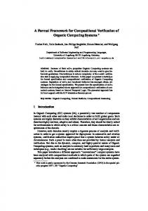
Figure 1. Overview of Bare Model Figure 1 shows the proposed development cycle of embedded reactive applications. We start by modeling the system using an extension of the X-Machine model that deals with embedded reactive systems; this extension is called BARE model. Considering that the BARE model is not executable, after the modeling phase we call the GeneratorXM which aims to transform the BARE model to a tabular model. The tabular model may be executed by a runtime environment, in this method called ExecutorXM. The proposed method also provides means to verify formally the properties of the system. Therefore, it is possible to translate from the tabular model to a specific input of a model-checker, in this case, we adopt the NuSMV model-checker. The main parts of the proposed method are described in the following subsections.
3.1.
The BARE model
The BARE model extends the X-Machine model specifically to deal with embedded reactive systems. In this context, we consider that all applications are composed by three main components: (1) Sensor, which is responsible for providing data to the application. This data generation can be time-triggered or event-triggered; (2) Transformer, which is responsible for implementing each application requirement; and (3) Communicator, which is responsible for all aspects related to send data to other devices. We propose to adopt X-machines for both Sensors and Communicators and consequently connecting them as an unique component. In this paper, however, we focus mainly on the transformer component, which is targeted to embedded reactive applications and is developed in a domain-specific basis. All three parts are further placed together into a single application for execution on a embedded platform. The BARE model extends the XMachine model in the following way: BM = (T , Σ, Γ, Λ, Q', M, E, C, Φ, F, q0, m0) where: •
T is a set of basic data types.
•
Σ is the input alphabet, which is called monitored variables.
•
Γ is a set of output alphabet. This definition is the same as the X-Machine. Γ is called controlled variables.
•
Λ is a set of internal alphabet or internal variables.
•
Q' = Q ∪ {Init,Start,Halt}, is the set of states. The purpose of the states Init, Start, Halt is to perform initial configuration (state Init) or initialization (state Start), and indicate when the application terminates (state Halt). We propose that the first state to be executed in any application is always the state Init, and after the state Start.
•
M is the set of values of variables in memory. This definition is the same as the X-Machine.
•
E is the set of Events. Events may be fired whenever a change occurs in the value of the variables (monitored, controlled, internal).
•
C is the set of Conditions. Conditions are logical expressions that rely on events. They are composed by variables from memory and linked by logical connectors.
•
Φ is a finite set of partial functions φ, that transforms an input alphabet and a value of memory into an output alphabet and a new value of memory, enabled by a condition when an event occurs. φ : Σ × M × C → Γ × M.
•
F is a partial function of the next state, given a state and a function of the type Φ, it denotes the next state. F normally is described as a diagram of state, F : Q × Φ → Q.
•
q0 ∪ Q' is the Init state. This definition is the same as the X-Machine.
•
m0 ∪ M is the initial values of variables in memory. This definition is the same as the X-Machine.
3.2.
Mapping the BARE Model to the Tabular Model
The BARE model is a specification model and, therefore, it is not executable. The next step on the proposed method is to transform the BARE model into a tabular model. This tabular structure is constructed with the aim to transform a specification model to a executable model, in such a way to make it easy to execute the application on the target platform. This kind of tabular model has been used for several years as a tool for software specification [3, 9, 11], with the aim of making systems more readable and understandable. The transformation from the BARE model to the tabular model is performed automatically by a specific tool called GeneratorXM. The columns of the application table are filled in with the information obtained directly from the BARE model. The resulting table is composed by the following columns: (i) Source represents the initial states of the transitions. The Source column should contain all states including the states Init, Start, Halt. The transitions between states are controlled by events. As sj = F(si, φi). In this case, this column should contain all si ∪ Q'; (ii) Input contains the input event to be considered in the transition between states. As 〈γk, mk+1〉 = φk(σk, mk, ck), the Input column should contain all σk ∪ Σ. (iii) Mem_input are internal variables values that will be considered in the condition to enable state transitions. As 〈γk, mk+1〉 = φk (σk, mk, ck), the column should contain all ; (iv) Target is the target state of transitions. As sj = F(si, φi) . In this case, the Target column should contain all sj ∪ Q'; (v) Condition is the condition to be evaluated in order to enable the transition from the current state to the target state. The conditions are synchronized by the input events. As 〈γk, mk+1〉 = φk (σk, mk, ck), the Condition column should contain all ck ∪ C; (vi) Mem_output are internal variable values of the machine that will be updated if the transition is taken when the condition ck is satisfied. As 〈γk, mk+1〉 = φk (σk, mk, ck) , the column Mem_output should contain all mk+1 ∪ M; (vii) Output is the value produced as a result of the transition between states. The output may trigger some other event or produce some output data. As ,〈γk, mk+1〉 = φk(σk, mk, ck), the Output column should contain all γk ∪ Γ.
3.3.
Formal Verification of Tabular Model
The technique chosen to verify the system is model checking [12], and the model checker adopted is the NuSMV [4]. The input language of the NuSMV model checker is a finite state machine (FSM), which makes it easier the translation from the BARE model. The model must describe the transition relation of the states through valid transition relations of the machine. The construction of the system’s model from the Bare model will be carried out through a tabular model, which contains all the needed elements to extract the
transition system. The mapping of the tabular model to the system’s model is thus done automatically by the GeneratorXM, which is based on the following algorithm: 1. Construction of the elements of the VAR section. (a) The variables in memory are selected from the set M of the BARE model. If needed, types are required explicitly from the user. (b) All events, either input or output, are declared as boolean type. The events come from the sets Σ and Γ of the BARE model. (c) All states, except for the states Init and Start, are declared in a variable called states. This variable has enumerated type with all states of the system. These states come from the set Q' of the BARE model. 2. Construction of the elements of the ASSIGN section. (a) All variables are assigned to its initial value. When needed, these values are required explicitly from the user. (b) The variable states is assigned to the target value of the transition “start” of the tabular model. 3. Construction of the transition between states through the CASE expression. (a) For each line of the tabular model, we construct an expression to the next state of the system as follows: states = Vi[1] & Vi[5] : Vi[4], where Vi[j] means jth column of the line i.
3.4.
ExecutorXM: The Runtime Environment for the BARE model
The application consists in an array of monitored variables m = [m1 , . . . mt], an array of internal variables i = [i1 , . . . im], an array of controlled variables c = [c1, . . . cn], and a finite directed graph G = (V,A), where the following conditions are satisfied: (1) There is only one vertex called “Init” (I ∪ V); there is only one vertex called “Start” (S ∪ V); there is only one vertex called “Halt” (H ∪ V); and any vertex v is in the path from S to H; (2) Each arc a not incident in H is associated with a quantifier-free formula of type Pa(m,i) and an assignment i ← fa(m,i); Each arc a incident in H is associated with a quantifier-free formula of type Pa(m,i) and an assignment c ← fa(m,i) ; where Pa means test predicate associated with arc a, and Pa(m,i) is called test formula associated with arc a; (3) For each vertex v ≠ H, let a1, a2, . . . ar be all arc leaving v and let Pa1, Pa2, . . . Par the test predicates associated with with arcs a1, a2, . . . ar, respectively. Thus, for all m and i, one and only one of the Pa1(m,i), Pa2(m,i), . . . Par(m,i) is true. After the construction of the graph, the application execution occur in accordance with the following algorithm: 1. Execution starts on vertex Init (I) and next the control is given to the vertex Start (S). 2. Let j = 0, vj = S and ij the internal variables. 3. If vj= H, then execution ends, otherwise go to step 4. 4. Let ak the arc in which vj is the source vertex, and the test formula associated with the arc is true, that is, Pak(m,ij) = true . Let vj+1 be the target vertex of ak. Thus, the control moves, through ak, to the vertex vj+1 and one of the following assignments is executed: •
ij+1 ← fak (m,ij), if vj+1 ≠ Η ;
•
c ← fak (m,ij), if vj+1 = Η ;
5. Let j=j+1, go to step 3. One platform adopted for execution of the runtime environment was the LEGO Mindstorm Robot [15]. The ExecutorXM was implemented in the LUA language [10]. This implementation is composed by two main
functions: Executor and ReadCurrent. The Executor is the main function. It receives a file with the application in the tabular format, always starts by state “init”, and executes up to state “halt” is reached. ReadCurrent receives as input the current state and returns all lines of the application that has this as source state. All such lines are evaluated in order to capture all input events of column “Input” and put in a list of monitored events. When an event occur, the next step is to find out what condition is true. We consider that just one condition will be true in each event. After that, the event in the column “Output” is executed. Later, “Mem_Output” is updated, in such a way that internal variables are updated, and the next current state is defined by column “Target”.
4. THE ENVIROTRACK CASE STUDY This section describes the main characteristics of the EnviroTrack case study [1], and shows results of the application of the proposed method in the modeling, verification and synthesis.
4.1.
Problem Specification
EnviroTrack aims to detect and track moving targets in a network of sensors. One sensor node can be in one of the following states: free, follower, member or leader. Initially a node is in the free state. A node free becomes member when it detects a target. A node free becomes a node follower if it has not detected any target, but it is in the neighbourhood of a member and received a heartbeat that a target was detected. The sensor node in free state does not respond to time event and leader election event. A node leader is a node that was member and was elected for this purpose. All members send their location to the leader, which performs a fusion of the positions for estimation on the position of the target object. If the node leader loses the detection of the intruder, it passes to the state of follower and other node member must be elected as leader. The members send specific signals (heartbeat) so that the free nodes that are in their neighbourhood may become a follower. The follower has a timer, and if it has not detected a target in a timeout, it returns to be free state. Figure 2 shows a high-level model of the EnviroTrack application.
Figure 2. Envirotrack application
4.2.
EnviroTrack’s BARE Model
The BARE model of the EnviroTrack case study is defined by the following tuple: BM = (T , Σ, Γ, Λ, Q', M, E, C, Φ, F, q0, m0), where: 1)
T = (Int, Bool, Temp = [0, 10000]);
2) 3) 4) 5)
Σ=(mSound={Bool}, mIntruder={Bool}, mElect={Bool}, mTemp={Temp}, mX={Int}, mY= {Int}); Γ=(cSound={Bool}, cPosX={Int}, cPosY={Int}); Λ=(iX={Int}, iY={Int}, iCurr={Temp}, iTotal={Temp}); Q' = {Free, Follower, Member, Leader, Init, Start, Halt };
6) 7) 8)
M=(mSound, mIntruder, mElect, mX, mY, mTemp, iCurr, iTotal, iX, iY, cSound, cPosX, cPosY); E={e1=mSound ∪ e2= mIntruder ∪ e3=mElect ∪ e4=mTemp}; C ={ {c0= True}, {c1= e1}, {c2=e2 }, {c3=e3 }, {c4= iCurr > iTotal ∪ e4 }, {c5= iCurr