Department of Computer Science, The University of Texas at Dallas. Richardson, Texas ... Our approach for software development is based on the Reserved ...
A Graph Grammar Approach to Software Architecture Verification and Transformation Jun Kong, Kang Zhang, Jing Dong, Guanglei Song Department of Computer Science, The University of Texas at Dallas Richardson, Texas 75080-0688, USA {jxk019200, kzhang, jdong, gxs017800}@utdallas.edu
Abstract Software architecture and design are usually modeled and represented by informal diagrams, such as architecture diagrams and UML diagrams. While these graphic notations are easy to understand and are convenient to use, they are not amendable to automated verification and transformation. This paper provides graph grammars for architecture and UML class diagrams. These grammars enable a high level of abstraction for the general organization of a class of software architectures, and form a basis for various analysis and transformations. In this approach, software verification is performed through a syntax analyzer. Architecture transformation is achieved by applying predefined transformation rules.
1. Introduction Graphic notations are widely used in software design and development. These notations can greatly help on the modeling and representation of software architecture [1] and design [2]. There are many benefits of informal graphic notation: first, it can be used for conveying complex concepts and models, such as object-oriented design. Notations like UML are very good at communicating designs. Second, it can help people grasp large amount of information more quickly than text can. Third, as well as being easy to understand, drawing diagrams is normally easier than writing text in a predefined language. Fourth, graphical notations cross language boundary and can be used to communicate with people of different cultures. However, there are shortcomings of informal graphical notations, e.g. informal graphical notations are sometimes imprecise and ambiguous. They are not amendable to automated analysis and transformation. The developer has to rely on personal experience to discover errors and inconsistencies in the architecture/design diagrams. She also has to manually transform an architecture/design diagram while needed. These processes are tedious and error-prone. This paper proposes an approach that can automatically verify and transform architecture/design diagrams based on graph grammars. The approach abstracts UML class diagrams and architecture styles into graph grammars. It then parses a given architecture/design diagram to analyze whether the diagram has some
required properties or reconciles some design principles. Moreover, architecture transformation can be achieved through graph rewriting. Graph grammars provide a theoretical foundation for graphical languages [3]. A graph grammar consists of a set of rules, which illustrates the way of constructing a complete graph from a variety of nodes. Graph grammars specify all possible inter-connections between individual components, i.e. any link in a valid graph can be eventually derived from a sequence of applications of grammar rules. Conversely, an un-expected link signals a violation on the graph grammar. A graph grammar can be used to “glue” various components into a complete system. Graph grammars form a formal basis to verify architectures in a diagrammatic notation, and are viewed as a model to simulate dynamic evolution. In general, our approach facilitates the following aspects: • Graphs are used to specify software by distinguishing individual components and their relationships. Using graph grammars as design policies, our approach provides a powerful mechanism for syntactic checking and verification, which are not supported by most current tools. • In addition to software design and verification, our approach facilitates a high level of software reuse by supporting the composition of design patterns, and uses graph rewriting techniques in assisting the transformation of software architectures and in reusing the existing products. The rest of this paper is organized as follows. Section 2 outlines our approach and briefly introduces the underlying graph grammar formalism. Section 3 illustrates how to verify software design using a graph grammar. Section 4 demonstrates the support for the composition of design patterns. Section 5 shows the mechanism for software architecture transformation, followed by related work in Section 6. Section 7 concludes our approach and proposes future research.
2. Outline Our approach for software development is based on the Reserved Graph Grammar formalism (RGG) [4]. An authoring module provides a graphical tool for the user to design software. Our approach can also directly take architecture and design diagrams as input, and run through
an automatic transformation. Graph grammars abstract design principles, which should be applied to well-formed software architectures. The syntax analyzer, which performs verification (parsing) and/or transformation (graph rewriting) on user-designed software architectures, is the key of the whole approach. A graph grammar is made P Class up of a set of rewriting rules P C called productions as Class := P illustrated in Figure 1. Each C Class production consists of two C Figure 1. A production in graphs, called left graph and right graph. A graph RGG transformation is a sequence of applications of productions. Applications are either Lapplications or R-applications. An L-application/Rapplication is to replace a graph in the input graph with the right/left graph of a production. The process of parsing a graph can be viewed as a sequence of R-applications to an input graph. If it is eventually transformed into an initial graph, the input graph belongs to the class of graphs defined by the graph grammar. The RGG formalism is expressed in terms of diagrams in a node-edge format, which are very similar to the “box and line” drawings [5] and suitable for automatic analysis based on graph grammars. In a RGG, nodes are organized into a two-level hierarchy as illustrated in Figure 1. A large rectangle is the first level called a super-vertex with embedded small rectangles as the second level called vertices. In a node, each vertex is uniquely identified. For convenience and simplicity, we assign a capital letter to each vertex according to the designer’s convention (In most cases, the vertex, e.g. P in Figure 1, is named by the other node, e.g. Parent class in Figure 1, to which it is connected). The name of a super-vertex distinguishes the type of nodes as the type of variables in conventional programming languages. A node can be viewed as a module, a procedure or a variable, etc., depending on the design requirement and granularity. Edges are used to denote communications or relationships between components. Either a vertex or a super-vertex can be the connecting point of an edge. In addition to structural information, the RGG provides a means of associating data to nodes in terms of attributes. An attribute expresses a piece of data related to the component represented by a node, and can be retrieved and evaluated in the process of parsing. Therefore, a software architecture represented through RGG notations can be executable.
3. UML class diagram verification In this section, we first use an example to illustrate representation of a class diagram in a RGG diagram. We then define a graph grammar for the UML class diagram. A parser can verify some properties of the design. In the next section, we show how this graph grammar can help
visualizing design pattern applications and compositions in their class diagrams.
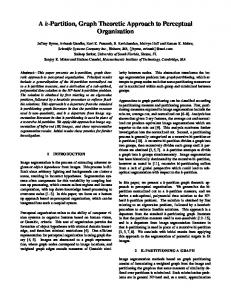
3.1. Graph grammar definition of class diagrams Class diagram, one of the most popular diagrams in UML, visually models the static structure of a system in term of classes and relationships between classes [2]. In order to verify the structure of a class diagram, we translate a class diagram (Figure 2(a)) into a node-edge format (Figure 2(b)), on which the RGG parser operates. In the class diagram, classes are represented by compartmentalized rectangles. In a node-edge diagram, a node labeled Class denotes the first compartment containing the class name. A set of nodes labeled Attri represents attributes in the second compartment. Nodes are sequenced by linking two adjacent attributes in the same order as displayed in the compartment, and the sequence is attached to a class by linking the first Attri node with the Class node. Operations in the third compartment are processed in the same fashion as attributes by replacing Attri with Oper nodes. Associations denoted by straight or diagonal lines in UML carry information about relationships between classes. In a node-edge diagram, a node labeled Asso is used to symbolize an association. A line connecting an Asso to a Class node holds the association. Associations may be named. In order to indicate the direction in which the name should be read, the vertex labeled R inside an Asso node is connected to the Class node designated by the verbal construct, and the vertex labeled L to the other Class node. On the other hand, if the order is unimportant, we ignore the difference between R and L. Aggregation and Composition, two special types of associations, are translated in the same way as associations. In UML, the generalization specifies a hierarchical relationship between a general description and a specific description. In the node-edge representation, a line, which links from the vertex labeled c in a Class node to the vertex labeled p in the other Class node, designates the generalization relationship from the former class to the latter. In other words, the vertex labeled c indicates the general class, and the vertex labeled p denotes the specific class accordingly. We introduce a new node to the node-edge representation, namely root, without a counterpart in the class diagram. The root is connected to any Class node representing a class without a super-class. The introduction of the root node is to facilitate the parser to verify the structure of a RGG diagram. A graph grammar abstracts the essence of structures. It, however, is not suitable to convey precise information visually. We store specific information into attributes. For example, association names are recorded in attributes associated with Asso nodes. Those values of attributes can be retrieved and evaluated in the parsing process.
the initial state. The nodes and vertices in dotted rectangles define pattern-extended class diagrams, which will be explained in Section 4.
Figure 2(a) illustrates a class diagram and Figure 2(b) presents its corresponding node-edge diagram recognizable by its RGG. The shaded texts in Figure 2(a) represent an extension to UML with pattern names, and the dotted rectangles in Figure 2(b) correspond to the extended UML [6]. We will discuss the pattern aspects in Section 4.
component
+Add(Component) +Remove(Component) +GetChild(int)
There are already some tools supporting the general syntactic checking on class diagrams. However, they are Root
Component {Composite[1]:Component} {Decorator[1]:Component} +Show()
3.3. Automatic verification
A
{Composite:Operation} {Decorator:Operation} {Composite:Add} {Composite:Remove} {Composite:GetChild}
C
children P Pattern P Pattern
R
E C
Aggr L Content {Composite[1]:Leaf} +Show() {Composite:Operation} {Decorator:Operation}
Component->Show();
Inter
+Show() {Operation} +Add(Component) {Add} +Remove(Component){Remove} +GetChild(int) { GetChild}
E
P
Class -addedState {addedState} +Show()
{Operation}
ConcreteContextB {ConcreteDecorator } +Show() {Operation} +AddedBehavior() {AddedBehavior}
A R
C Context::Show(); AddedBehavior();
(a) A class diagram
E C
For all g in children g.Show(); ConcreteContextA {ConcreteDecorator }
R
Composite {Composite}
{Decorator[1]:ConcreteComponent}
+Show() {Operation}
P Attri N
P Oper N
R
P
E
P
E R
A
C
Class R
Class
A
C
P Oper N E P
Class R C
A
Aggr L
R
Context {Decorator}
P
Class
P
Class
Inter
A
P Oper N
P Oper N
N Oper P
Inter
P Oper N
N Oper P
A
P Oper N
P Oper N
N Oper P
P Oper N P Oper N P Oper N
(b) The corresponding RGG diagram
Figure 2. A class diagram and its corresponding RGG diagram
3.2. The RGG for class diagrams A graph grammar can be viewed as a style that any valid graph should hold, i.e. any possible inter-connection between entities must be specified in the grammar. One production demonstrates the relationships between local entities. Integrating all productions together, a RGG grammar defines the way of constructing a valid class diagram through different entities represented by nodes with different types. Figure 3 presents the RGG for class diagrams. Production 1 reduces two attributes into one node, which is treated as one entity in later applications. Repetitive applications of Production 1 reduce attributes of the same class to one entity, which will be applied by Production 3 later. Productions 1 and 2 serve to reduce a sequence of attributes and operations. Production 3 specifies the class structure by attaching sequences of operations and attributes to a Class node. Production 4 defines the constraints between associations. Production 5 specifies the template class, followed by the production presenting the interface. Productions 7, 12 and 14 define associations, and Productions 8 and 9 specify aggregation and composition respectively. Productions 10 and 13 demonstrate the generalization. Production 15 represents
not capable of performing specific verification. For example, multi-inheritance may cause ambiguity, it is desirable to prohibit it when modeling software written in conventional programming languages. Each production specifies a local structure. By “gluing” separate structures together, repetitive applications of various productions can generate a complete structure. A graph specifying a structure is invalid if it breaks at least one relationship specified in any production. For example, Production 6 in Figure 3 define one interface can only attach to one class. If an interface is designed to be related to more than one class, a parser can indicate a violation of Production 6. The following example illustrates how to verify inheritance relationships between classes. In Figure 3, Production 10 defines the case of single inheritance, and Production 13 specifies that of multi-inheritance. Since any valid relationship between components can be eventually derived from a graph grammar, removing Production 13 implicitly denies multi-inheritance. In order to explain in detail how to invalidate multi-inheritance, we need to introduce the marking technique [4]. In a RGG, vertices are classified as marked and unmarked ones. A marked vertex preserves outgoing edges connected to vertices outside a replaced sub-graph. A marked vertex is distinguished by assigning to it a unique integer, the value
Attributes 1:P Attri 2:N
:=
Operations
1:P Attri N
1:P Oper 2:N
P Attri 2:N
:=
Class
1:P Oper N
1:P
2:R
2:S C
1:L
E A 3:C
:=
E A 3:C
4:T
P Attri N
P Oper N
5:L
Asso 3:R
4:T
:=
6:S C
1:P
Asso 7:R
:= Inter
1:P
Class 2:R
4:Class E A 3:C
E A 3:C
4:P
1:P
6:R Class E A 5:C
E A 3:C
:= Class 2:R
L Asso R T
E A 3:C
4:Class E A 3:C
Inheritance
4:P
S C
1:P 2:R
:= Ins
E A 3:C
8:T
8:T
2:R
4:Class
6:S C
5:L
Asso 7:R
Template class
2:S C
1:L
Asso 3:R
Association 1:P 2:R
4:Class
Constraints
2:R
4:Class
4:Class
P Oper 2:N
Interface 1:P 2:R
1:P
1:P
6:R Class E A 5:C
1:P
Class R E 2:C A
:=
Class R
P
E 2:C A
Class R
Aggregation 1:P
Class 2:R E A 3:C
E C A
4:P
:=
6:R Class E A 5:C
1:P
L Comp R
Class 2:R
Classes
4:P 6:R Class E A 5:C
E A 3:C
Root
A
Composition 1:P
Class 2:R E A 3:C
4:P
Class :=
6:R E A 5:C
1:P
1:P
Class R
Class R
E 2:C A
E 4:C A
1:P
Class R E C A
E A 3:C
Class R E 4:C A
E 2:C A
:=
Class 2:R
3:P
Class R
λ :=
Class R
E
C
A
:=
4:T
A
1:L
E
R
A
2:S C
Asso 3:R
Root
A
1:P
:= Class 2:R E A 3:C
Patterns L R
S C
Root 1:A 2:C
Asso T
:=
Root 1:A 2:C P Pattern
Pattern reduction
Initial
1:P
C
Asso 3:R
P
Class C
4:T
1:P
3:P
1:L
2:S C
Reflective association
Multi-inheritance 1:P
P E
6:R Class E A 5:C
E A 3:C
:=
1:C
Class R
4:P
L Aggr R
Class 2:R
1:C
Association class
Root
A
C
7:P 8:Pattern
1:P
2:R
6:Class
:=
7:P 8:Pattern
5:E 4:A 3:C
1:P
2:R
6:Class 5:E 4:A 3:C
Figure 3. The graph grammar for class diagram P
P
Class R E
C
Dangling edge
A
Class R E
C
A
Reserved edge
P E
C
(a) Illegal inheritance
E
A
Class R E
C
C
A
P
P
Class R
4. Design pattern visualization
P
Class R
A
Class R E
C
A
(b) Legal inheritance
Figure 4. Inheritance verification
of which is sequenced starting from one inside a production. The same principle applies equally to supervertices. In the right graph of Production 10, the edge indicates an inheritance relationship between the classes. The unmarked vertex p in the bottom class node representing a sub-class requires that any class can only inherit from one class. On the other hand, the marked vertex c in the top class node representing a super-class defines that one super-class can have more than one subclass, which does not contradict with single inheritance. If the multi-inheritance as illustrated in Figure 4(a) occurs, the application of Production 10 causes a dangling edge [3], which is not allowed in the RGG formalism. Concerning the case that one class has more than one subclasses, a successful application is shown in Figure 4(b).
UML [2] provides a set of notations to demonstrate different aspects of software systems. However, it is still not expressive enough for some particular problems, such as visualizing design pattern applications and compositions [6]. In this section, we use the RGG formalism to visualize design patterns in their class diagrams. Design patterns [7] document good solutions to recurring problems in a particular context, and their compositions [8] are usually modeled using UML. When a design pattern is applied or composed with other patterns, the pattern-related information may be lost because UML does not track this information. Thus, it is hard for a designer to identify a design pattern when it is applied or composed. The benefits of design patterns are compromised because the designers cannot communicate with each other in terms of the design patterns they use when the design patterns are applied or composed. Several graphic notations have been proposed to explicitly represent pattern-related information in UML class diagrams [6]. While all these solutions need to attach additional symbols and/or text, they all suffer scalability problem when the software design becomes very large.
We propose a solution that can dynamically visualize pattern-related information based on the RGG. As shown in Figure 3, we introduce a new type of nodes, called pattern, which denotes a specific pattern, and patternrelated information is expressed by linking a pattern node with its associated class nodes. Figure 2(b) presents the corresponding node-edge diagram by highlighting the newly introduced nodes and edges with dotted lines. A syntactic analyzer can dynamically collect separate pieces of information, and reconstruct them into an entity. In the process of parsing, the sequence of applications of Production 17 in Figure 3 collects all classes belonging to the same pattern together. For example, if the user clicks the composite class in Figure 2(a), the component class, content class and composite class, which belong to the Composite pattern, are highlighted. Therefore, there is no need to attach any additional information on the original class diagrams.
the data server directly replies to the client. Such a communication pattern is defined in Figure 5(c), which is achieved through the transformation rule in Figure 5(d).
1:C
Server
:=
1:C
S Client
(a) Client-server style C Data
Server C
S Client
S Client
S Client
1:Server
1:Server
2:C
S Client
(c) An evolved architecture
S Client
(b) An architecture with the client-server style
C Data
S S S Client Client Client
S Client
2:C :=
S Client
C Data
(d) Transformation rule
Figure 5. Architectural transformation
5. Software architecture transformation The architectures of software systems are usually not fixed. With the changes of requirements and contexts, software architecture may be transformed into a new configuration. Furthermore, a high-level software architecture needs to be refined into detailed architecture [9] in software development. This transformation process can be tedious and error-prone without tool support. This section illustrates the automated transformation of software architecture between different styles. Graph rewriting provides a device for reusing existing products by performing a transformation. A software architecture style defined through a RGG characterizes some common properties shared by a class of architectures. To satisfy new requirements and reuse current designs, an architecture with one style needs to evolve into another with a more appropriate style in the new contexts. In general, software architecture transformation proceeds in two steps: a) verify the style of an architecture; b) transform an architecture from one style to another style. Assume that a system is originally implemented in a client-server style, only consisting of one server storing all data. In order to retrieve data, clients must send requests to and receive responds from the server. This communication pattern is abstracted into a graph grammar shown in Figure 5(a), and an architecture with that style is illustrated in Figure 5(b). With the increase of the amount of data and communication, one server may not be able to bear clients’ requests. On possible solution is to distribute data to different servers. Therefore, we need to transform our current style to a more advanced one. We divide servers into control server and data server. A system can only contain one control server, but may have several data servers. A client sends requests to the control server, which forwards them to an appropriate data server. Then,
Server C
Server
1:I Task 2:O
:= L
I Task 1:O L Str 2:R
Str R
:=
1:I Task 2:O
I Task 1:O
L Str 2:R
Ø:= I Task O (a) Pipe and filter system (b) RGG definition of pipe and filter system without feedback
L Str R L Str R L Str R L Str R
I Task O
L Str R L Str R
I Task O
L Str R
I Task O
I Task O L Str R
L Str R I Task O
L Str R
I Task O
L Str R
(c) The node-edge representation for the example system 1:I Task 2:O
3:I Task 4:O
:= 1:I Task 2:O
3:I Task 4:O
(d) The transformation rule
(e) Pipe and filter system with feedback
Figure 6. Pipe and filter system
We go through another example to illustrate the architecture transformation. A simple pipe and filter system without feedback is shown in Figure 6(a), where a circle represents a task and a directed edge indicates a stream between tasks. Correspondingly, a node labeled Str/Task simulates a stream/task in the node-edge representation. An edge connecting the R/L vertex in a Str node to the I/O vertex in a Task node expresses an incoming/outgoing stream. Figure 6(c) illustrates the node-edge representation for the system shown in Figure 6(a). Productions defined in Figure 6(b) abstract the communication pattern in pipe and filter systems without feedback. By allowing an edge between Task nodes, which designates a feedback between tasks, the transformation rule given in Figure 6(d) transforms a
system without a feedback to one with feedback. Figure 6(e), where the dotted edges represent feedbacks, illustrates the system with feedback after we apply the transformation rule to the example in Figure 6(a).
6. Related work Dean and Cordy [10] present a diagrammatic representation of software architectures. A graph exploits the structure of a software architecture, and a graph grammar abstracts the overall organization of a class of architectures. Based on the equivalent of context-free grammars, Dean and Cordy introduce a pattern matching mechanism for recognizing classes of software architectures. Métayer [11] also defines the style of architectures using graph grammars. Instead of discussing pattern matching over software architectures, Métayer emphasizes on the dynamic evolution of an architecture, performed through graph rewriting. An algorithm is presented to check whether an evolution breaks communication constraints. The underlying formalism is defined in in terms of set theory, and thus is not as intuitive as in RGGs. Compared with our work, the expressiveness of the above two approaches is limited by their underlying graph grammar formalisms, while the RGG formalism is more powerful at conveying structural information. The other distinction is that our work emphasizes on transformations between different styles rather than recognition or evolution within the same style. Radermacher [12] discussed graph transformation tools supporting the construction of an application conforming to a design pattern, which is specified through graph queries and graph rewriting rules. A prototype can be generated by the PROGRES environment [13]. Since our approach conforms to UML, it has a broader acceptance and application scope than the above tools.
7. Conclusion Based on a graph grammar formalism, this paper presents an approach for software architecture definition, verification and transformation. Through our approach, UML notations can be easily translated to the graphical notations adopted by the RGG formalism. The conformity makes our approach consistent with current design tools. In general, our approach can provide the following benefits: 1. Consistent: It expresses software architectures in terms of “box and line” drawings [5], which meets the common practice of software engineers [11]. 2. Scalable: The underlying graph grammar formalism is applicable to various classes of graphs. It is easy to accommodate new components by extending the graph schema and revising corresponding grammar rules, and thus support software reuse.
3. Automatic: Automatically generated by a visual language generator [14], a transformation tool is capable of syntactic checking of software architectures. Automatic transformation from one architecture style to another assists software engineers to reuse existing products in the new application contexts. In addition to syntactic checking and transformation, we are working on semantic analysis and transformation. Using the attributes in the RGG, we can express semantic information of software architecture and design. Thus, our approach will adapt to wider applications.
References: [1] M. Shaw and D. Garlan, “Software Architecture: Perspectives on an Emerging Discipline”, Prentice Hall, 1995. [2] G. Booch, J. Rumbaugh, and I. Jacobson, The Unified Modeling Language User Guide, Addison-Wesley, 1999. [3] G. Rozenberg (Ed.), Handbook on Graph Grammars and Computing by Graph Transformation: Foundations, Vol.1, World Scientific, 1997. [4] D. Q. Zhang, K. Zhang, and J. Cao, “A Context-Sensitive Graph Grammar Formalism for the Specification of Visual Languages”, The Computer Journal, 44(3), 2001, 187-200. [5] R. Allen and D. Garlan, “Formalizing Architectural Connection”, Proc. 16th Int. Conf. Software Eng., 1994, 71-80. [6] J. Dong and K. Zhang, “Design Pattern Compositions in UML”, In K. Zhang (Ed.), Software Visualization – from Theory to Practice, Kluwer Academic Publishers, 2003, 287- 208. [7] E. Gamma, R. Helm, R. Johnson, and J. Vlissides, Design Patterns, Elements of Reusable Object-Oriented Software, Addison-Wesley, 1995. [8] R. K. Keller and R. Schauer, “Design Components: Towards Software Composition at the Design Level”, Proc. 20th Int. Conf. Software Eng., 1998, 302-311. [9] M. Moriconi, X. L. Qian, and R. A. Riemenschneider, “Correct Architecture Refinement”, IEEE Trans. Software Eng., 21(4), 1995, 356-372. [10] T. R. Dean and J. R. Cordy, “A Syntactic Theory of Software Architecture”, IEEE Trans. Software Eng., 21(4), 1995, 302-313. [11] D. L. Métayer, “Describing Software Architecture Styles Using Graph Grammars”, IEEE Trans. Software Eng., 24(7), 1998, 521-533. [12] A. Radermacher, “Support for Design Patterns through Graph Transformation Tools”, Proc. Application of Graph Transformations with Industrial Relevance, LNCS 1779, 1999, 111-126. [13] A. Schürr, A. Winter, and A. Zündorf, “The PROGRES Approach: Language and Environment”, In G. Rozenberg (Ed.), Handbook on Graph Grammars and Computing by Graph Transformation: Applications, Vol.2, 1999, 487-550. [14] K. Zhang, D-Q. Zhang, and J. Cao, “Design, Construction, and Application of a Generic Visual Language Generation Environment”, IEEE Trans. Software Eng., 27(4), 2001, 289307.