A Linear 3D Elastic Segmentation Model for Vector Fields. Application to the Heart Segmentation in MRI
Martine Picq, J´erˆome Pousin, Youssef Rouchdy Institut C Jordan INSA de Lyon UMR CNRS 5042 F-69621 Villeurbanne Cedex France Abstract In this paper a 3D elastic model for the segmentation of vector fields has been proposed and analyzed. Elastic models for segmentation usually involve minimization of internal and external energy. A problem we observed with standard internal and external energy is that the local or the global reached minima do not force the external energy to be zero. To eliminate this difficulty, we propose introducing a constraint. The constraint problem is proved to be mathematically well posed, and a simple algorithm which avoids computing the lagrange multiplier is provided. This algorithm is proved to be convergent. Then the algorithm is applied to the segmentation of cardiac magnetic resonance imaging, and its efficiency is shown with two experiments.
Segmentation of a vector field, Minimization Problem subject to a Constraint, Elastic Finite Element model, Cardiac Image Segmentation.
1
Introduction
Volumetric biomechanical models for segmenting cardiac medical images uses a clinical Magnetic Resonance data set (MR volume data set). This volume data set is manipulated through a matrix V with x rows, y columns and z slices, that represent a discrete grid of volume elements ( or voxels) w ∈ {1, ··, X} × {1, ··, Y } × {1, ··, Z}. For each voxel w, we denote by G : IN3 −→ IN, w 7→ G(w) the gray level function. Data is anisotropic with an equal sampling in x and y directions but with a coarser density in the z-direction. By image segmentation we refer to processes which identify all voxels that belong to a group that share a homogeneity criterion (most often this criterion is the same anatomical structure). Segmentation is required for the identification of the object (i.e. the heart) in the M. R. volume data. Here we deal with edge-based algorithms which try to detect the borderline of a structure, that is to say the discontinuity surfaces of the ”gradient” H of the gray level function. 1
1.1
Meshing
Generally segmentation has three stages [8], [13], [2]. Firstly, a mesh of a given anatomical structure is created, in our case, a volumetric tetrahedra mesh of the heart including both left and right ventricles extracted from a databank. When creating a tetrahedral mesh, conditions have to be satisfied, such as the mesh size has to be chosen in order to keep the computation time reasonable and the shape quality of the tetrahedra must be sufficiently good for producing accurate results. In the experiments we provide at the end of the article, we use a quality criteria defined in [3] and used in this context in [3]. Here we briefly recall the definition of the quality criteria. Let S be a tetrahedron, we denote by hmax the largest length of its edges, VS its volume and by AS the total surface of its four S faces. The radius ρ = 3V largest ball included in S. The quality criteria AS is the√ ρ QS we used is given by: QS = 24 hmax . The criteria QS ranges from 0 to 1, equals 1 for a regular tetrahedron, the faces of which are equilateral triangles and equals 0 for a degenerated tetrahedron. If the values of QS fall below 0.1 the mesh is modified.
1.2
Rigid registration
The second step as a prerequisite is, using a rough scale, to apply a full affine transformation. The template is first scaled to correct dimensions, with respect to the image resolution, and translated so that a small number of reference points of the template and of the image match in a one to one way. We look for the 3-D rigid transformation T (r, t), where r = (rx , ry , rz ) and t = (tx , ty , tz ) are respectively the rotation and the translation vectors, which brings the template as close as possible to the anatomical structures of interest. The registration principle can be formulated within an energy minimization framework, where the global energy Eini to be minimized is composed of two terms Eini (T ) = Esurf (T )Eregion (T ) where Esurf (T ) denotes the surface energy and Eregion (T ) denotes the region energy. Multiplication of surface and region energies was preferred over addition because addition of the terms would require both terms to be normalized ([15]). The surface energy is related to the distance from the template’s boundary to detected edges in the image Esurf (T ) =
N 1 X d(nk (T ), edge) N k=1
with N the number of nodes on the surface mesh, nk the k-th node and d(·, ·) the Euclidean distance. The region energy, which is based on the mutual information criterion, measures the gray level similarity between the reference dataset and the image to segment, via a meshed domain W surrounding the template and sampling the gray values at its nodes Eregion (T ) = I(Wref , Wtarget (T )) 2
where I(·, ·) is the mutual information, Wref the gray values of the reference dataset carried by the nodes of W and Wtarget the gray values sampled on the image to segment. The reference dataset is the image from which the geometric model was extracted. This minimization is carried out using, for example, a powel multi-dimensional algorithm [16]. In Figure 1 results are presented for a mid-ventricular slice of a heart patient. The input data consists of a MR cardiac data set acquired from a patient with a 1.5T MR scanner (Siemens, Erlangen, Germany) using TurboFLASH squenses. The imaging parameters are: TR=80ms; TE=4,8ms; FOV=350 mm; NEX=1; matrix size = 256X256; slice thickness=8mm; ECG-gated with breathhold. Each sequence comprises 9 phases from end diastole to end systole. 8 short axis (SA) images cover the heart ventricles. The left picture represents the initial position of the template and the right picture represents the registration result.
(a)
(b)
Figure 1: (a): trace of the initial template, (b): rigid registration
1.3
Local Deformation
The last stage concerns the fine detail. The minimization of internal and external energy enables more local deformations. This stage is important when biomechanical models aim at specifying important physiological parameters. Classical computer vision uses an eventually ill-posed minimization problem involving internal and external energy which enables more local deformations. Due to noise and inhomogeneities in the gray levels, segmentation of the cardiac muscle in MRIs cannot be reduced to finding the exact zero level set of the external energy. Therefore, a regularizing flow is introduced, which in the deformable template context can be chosen as the linearized elasticity operator. On the one hand, the linearized elasticity operator prevents the undesirable changes of topology of the template allowing to handle some inhomogeneities 3
in the gray levels. Moreover, if necessary, a more sophisticated model adding boundary rigid constraints modelling crudely some biomechanical properties of the heart fibers can be incorporated (see [10]). On the other hand, the introduction of an elastic energy requires this energy to be balanced by the external energy (i.e. the work of the image forces) when a minimum is reached. There is no way for introducing such information with the gray level function. Therefore, a modified formulation of the minimization problem has to be introduced for handling the correct balance between internal and external energies. The goal of this article is to analyze how a biomechanical model evolves under the influence of both an internal energy computed from linear elasticity models, which represents physical properties of the organ, and an external energy computed from the image as defined in the framework of deformable templates, when noise and inhomogeneities have been filtered. Here the problem addressed is the segmentation of a vector field. A problem we have observed, with standard internal and external energy, is that the local or global reached minima do not impose the external energy to be zero. That is a serious limitation when the external energy is derived with the Gradient Vector Flow method (GVF) [19], since the zero level of the external energy is reached when the boundaries of the template fit with the image edges (see Figure 2 (a)). The remedy we have proposed is to introduce a constraint in order that the external energy becomes zero for the energy minimizer, which enforces the boundaries of the template to fit the image edges. For the convenience of the reader, let us briefly recall the main features of the Gradient Vector Flow method. One of the aims of the GVF is to extend the force field extracted from the gray level function with a diffusion process. Let I denote the gray level function of the image defined everywhere. The GVF method can be summarized in three steps. 1- Regularize with a smooth convolution kernel the function I, which is still denoted by I. 2- Compute the edge map f (x) = k∇I(x)k2 and set to zero the values of ∇f greater than a fixed large parameter. 3- Extend ∇f in a bounded domain O containing the image of interest with a diffusion process. For µGV F , a fixed inverse-diffusion parameter, compute t, the solution to ∆t − µGV F (t − ∇f )k∇f k2 = 0 in O; (1) t=0 on ∂O. Roughly speaking, when k∇f k2 is large t = ∇f , and outside of these regions, t is extended in a smooth way. Noise and heterogeneities in MR images are the principal difficulty in automatic segmentation. Thus the quality of the zero level of the GVF will give the quality of the final segmentation. This question is discussed in [18] (see for example Figure 3). The outline of the paper is as follows. The minimization problem induced by a linear elastic model under constraint is introduced, and an existence result for a minimizer is proved. Then an algorithm for computing a minimizer is proposed. In section 3 a toy problem is considered to analyze the convergence properties of the algorithm introduced in section 2. The 2D toy problem mimics some
4
difficulties of the segmentation algorithm (i.e. the derivative of the iteration function is not one to one), since it is quite hard to evaluate the convergence properties in such a situation. Finally, the paper ends with numerical examples and heart patient images segmented using our method.
2
Methods
We recall here briefly the basic concepts of elasticity in 3 dimensions. The reader can refer to [7] for further details on the elasticity theory. Here we address the typical problem of the deformation of an elastic body. Let Ω0 be the initial configuration of the elastic template, the deformation is described by the Green-Lagrange strain tensor which is linearized under the small deformation assumption. We denote by ²(v) = 12 (∇v + ∇v T ) the strain tensor and by σ(v) = λT r(²(v))II + 2µ²(v) the stress tensor as a function of the displacement v. The coefficients λ and µ stand for the Lam´e coefficients (see [7]). It is well-known that the equilibrium position of an elastic body corresponds to the minimum of the elastic energy: Z 1 F (v) = σ(v) : ²(v) dx (2) 2 Ω0 We assume that a bounded lipschitzian open domain O of IR3 exists such that V(Ω0 ), a Ω0 neighborhood, verifies V(Ω0 ) ⊂ O. Let t be the resultant of the external superficial forces which deform the template by acting on its boundary. The force field t is derived from the MR volume data set according to the Gradient Vector Flow method [19]. The external energy is defined as work produced by the force field t due to the deformation. The following hypotheses for the field t are convenient for analyzing the level set method on vector fields. • H1 The function t is defined on O, t ∈ C 1 (O; IR3 ) and its derivative Dt is bounded on O. As mentioned in the introduction, after the image has been filtered, the external energy zero level is reached when the boundary of the template corresponds to the borderline of the structure to be detected in the image. This implies that Dt the derivative of force field t is not a regular linear operator on the boundary of the deformed template, that is to say Dt is not one to one, since the zero level set of t is not constituted of isolated points. Let us mention that Hypothesis H1 is satisfied for the applications considered since t is the solution to the elliptic problem (1) with a regular right hand side. Let us now introduce the functional setting for stating the mathematical model we are dealing with. We denote by H 1 (Ω0 ) the classical Sobolev space of functions in L2 (Ω0 ) with a derivative in distributional sense in L2 (Ω0 ). H 1 (Ω0 ) = {ϕ ∈ L2 (Ω0 ); Dϕ ∈ L2 (Ω0 )} ¡ ¢3 (see [7]) and we set H = H 1 (Ω0 ) . 5
Let R be the subspace of rigid motions, which is defined as the kernel of the ³ ´3 strain tensor: R = Ker ², set IH = H 1 (Ω0 )/R the displacement space, equipped with the semi-norm k²(v)kL2 (Ω0 ) which, thanks to the Korn inequality, 1 is a Hilbert space. We denote by IH 2 the set of traces of displacements on ∂Ω0 (i.e. the traces of functions of IH). As mentioned before we are interested in deformations which bring the template boundary ∂Ω0 onto the zero level set for the external energy, so, for introducing this information into the functional setting, we define the continuous operator K as: K : IH → IH1/2 v
¯ ¯ 7→ t(I + v)¯
∂Ω0
Finally, let C denote the subset of admissible displacements: C = {v ∈ IH, K(v) = 0} which is closed. Please remark that a displacement belonging to C is a zero of the external energy. Let IF : IH → IR be the strictly convex IH-coercive function defined by Z 1 IF(v) = σ(v) : ²(v) dx. (3) 2 Ω0 The elastic model for the level set segmentation for vector fields reads: find u which verifies IF(u) = inf IF(v), (4) v∈C
˜ is recovered with Ω ˜ = (I + u)Ω0 . the image of the object to be detected, Ω, Theorem 1. Problem 4 has a solution u ∈ C. Moreover if we assume that the derivative DK(u) is a surjective operator belonging to L(IH; IH1/2 ), then we have the following optimality conditions: ∃ (λ, u) ∈ (IH1/2 )0 × IH be such that −div(σ(u)) = 0 in Ω0 ; σ(u) · n = −λ ◦ DK(u) = −λ ◦ Dt(I + u) on ∂Ω0 ; (5) K(u) = 0 i.e t(I + u)|∂Ω0 = 0, Let us comment on the hypothesis DK(u) is surjective. For image segmentation of the heart in MR context, it is very hard to check that this hypothesis holds true. In fact, this technical hypothesis is required for expressing the optimality conditions in a simple way. Please note that this condition is not used in the proposed algorithm 11 in the next section, but is just used for interpreting the link between the limit solution and the optimality conditions. Furthermore, this hypothesis will be satisfied by a penalized version of the force field t (see appendix B). Proof. From the compact injection of H 1/2 (∂Ω0 ) into L2 (∂Ω0 ) we deduce that C is weakly closed. Let {vn }n∈IN be a bounded sequence of C. Since {vn }n∈IN is bounded in IH a subsequence still denoted by {vn }n∈IN and v ∈ IH exist such 6
that vn weakly converges towards v. Accounting for the continuity of the trace operator from IH into IH1/2 and due to the compact injection of H 1/2 (∂Ω0 ) into L2 (∂Ω0 ), the subsequence {vn }n∈IN converges strongly towards the trace of v in L2 (∂Ω0 ). So there exists a subsequence still denoted by {vn }n∈IN converging almost everywhere towards v (see [9] Theorem 4.9 p. 58). The functional IF is weakly l.s.c (Theorem 2.1.3 in [1] p. 27) so we obtain the existence of a minimizer u ∈ C of Problem 4. The optimality conditions are deduced from Theorem 3.1.36 p. 124 in [4], that is to say λ ∈ (IH1/2 )0 exists where (IH1/2 )0 , also denoted by (IH−1/2 ), is the dual of the space IH1/2 such that minimizing IF over C is equivalent to minimizing IF(v)− < K(v), λ >H 1/2 ,H −1/2 over IH. Remark 1. Due to the third equation in (5), the second equation in (5) can be expressed as: σ(u) · n = t(I + u) − λ ◦ DK(u) (6) = t(I + u) − λ ◦ Dt(I + u) on ∂Ω0
2.1
An algorithm for computing the minimizer
The issue of this section is to propose an implementable algorithm. The convergence of this algorithm will be addressed in the next section. When the subset C is not convex the difficulties for solving Problem 5 are twofold: solving K(u) = 0 and computing the Lagrange multiplier λ. As has been mentioned in remark 1 the second equation of the optimality conditions can be modified. Therefore we first propose to replace the equation (52 ) by σ(u) · n = t(I + u) − λ ◦ DK(u) = t(I + u) − λ ◦ Dt(I + u) on ∂Ω0 .
(7)
Problem 5 with equation (52 ) replaced by the equation (7) is still a nonlinear problem. So we introduce the following iterative algorithm. Starting from u0 = 0 and for a given uk find (λk+1 , uk+1 ) ∈ (IH1/2 )0 × IH verifying −div(σ(uk+1 )) = 0 in Ω0 ; σ(uk+1 ) · n = t(I + uk ) − λk+1 ◦ DK(uk ) (8) = t(I + uk ) − λk+1 ◦ Dt(I + uk ) on ∂Ω0 ; K(uk+1 ) = 0 in Ω0 . To avoid computing the Lagrange multiplier λk+1 , we note that if Algorithm 8 converges, then σ(u∞ ) · n = −λ∞ ◦ Dt(I + u∞ ). (9) Thus we replace −λk+1 ◦ Dt(I + uk ) by σ(uk ) · n and equation (83 ) is cancelled out, because this condition is recovered implicitly for the limit u. Algorithm 8 becomes: starting from u0 = 0 and for a given uk find uk+1 ∈ IH verifying: ½ −div(σ(uk+1 )) = 0 in Ω0 ; (10) σ(uk+1 ) · n = t(I + uk ) + σ(uk ) · n on ∂Ω0 , 7
which is a linear elasticity problem. In order to be able to analyze the convergence of the algorithm, for 0 < β a fixed parameter, we consider the following algorithm which has the same limit as the previous one: ½ −div(σ(uk+1 )) = 0 in Ω0 ; (11) σ(uk+1 ) · n + β(uk+1 − uk ) = t(I + uk ) + σ(uk ) · n on ∂Ω0 , We obtain: Lemma 1. For uk ∈ H given, the problem 11 has a unique solution uk+1 ∈ H. Proof. The reader is referred to the lemma 1 proof in the next section. Let us check that if algorithm 11 converges, then the limit function u ˜ verifies the constraint: K(˜ u) = 0. 1 3 Lemma 2. Assume a sequence (u0 = 0, {uk }∞ k=1 ) ⊂ (H (Ω0 )) ) of solutions to the algorithm 11 exists which weakly converges towards u ˜. Then u ˜ verifies: u)) = 0 inPΩ0 ; −div(σ(˜ ∞ σ(˜ u) · n = −β(˜ u) + l=0 t(I + ul ) on ∂Ω0 ; (12) K(˜ u) = 0 i.e t(I + u ˜)|∂Ω0 = 0,
Proof. From (112 ) we know that t(I + uk ) weakly converges towards zero in ³¡ ¢ 3 ´0 H 1/2 (∂Ω0 ) . From the compact injection of H 1/2 (∂Ω0 ) into L2 (∂Ω0 ), up to a subsequence, we have ukp → u ˜ a.e. in ∂Ω0 . Then we deduce that t(I + u ˜) = 0 a.e. in ∂Ω0 . Now let us specify the relation between Problem 12 andh Problem 5. If we P∞ assume DK ∗ (˜ u) to be surjective, by defining µ ∈ DK ∗ (˜ u)−1 β(˜ u) − l=0 t(I + i ³ ´3 ul ) we obtain for all v ∈ H 1 (Ω0 ) < µ, DK(˜ u)vh>H −1/2 ,H 1/2 = i P∞ ∗ < DK (˜ u)−1 β(˜ u) − l=0 t(I + ul ) , DK(˜ u)v >H −1/2 ,H 1/2 P∞ =< β(˜ u) − l=0 t(I + ul ), v >H −1/2 ,H 1/2 ,
(13)
so the equation (122 ) can be rewritten as σ(˜ u) · n = −µ ◦ DK(˜ u), and thus u ˜ is a solution to Problem 4. Moreover, since DK ∗ (˜ u) is surjective, the Lagrange multiplier associated to u ˜ is unique. In [13] a similar algorithm has been implemented without accounting for the constraint. The equation (112 ) was replaced by σ(uk+1 ) · n = t(I + uk ) and the problem approximated with a tetrahedral finite element method of order one. This algorithm has been tested in [3]. Unfortunately the constraint K(u) = 0 was not verified (see Figure 2 (c) and (d)). 8
(a)
(b)
(c)
(d)
Figure 2: (a): a plane section of force field t, (b): trace of the initial template, (c): a trace of segmented data without constraint, (d) mesh of segmented data without constraint
9
(a)
(b)
Figure 3: (a): a trace of segmented data with the algorithm 11, (b): mesh of segmented data with the algorithm 11
2.2
Convergence of the algorithm in a finite dimensional subspace
As has been mentioned previously, the derivative of the function t is not a regular linear operator since the set of its zeros is the boundary of the object to be detected in the volume data set. In the Gradient Vector Flow strategy, the function t is built through a resolution of a P.D.E., so analyzing the mathematical properties of the function t is beyond the scope of this article. In what follows, first we are given sufficient conditions for proving the convergence of algorithm 11 when the space H is approximated with a finite dimensional subspace according to a Galerkin procedure. Then we are going to deal with a toy problem that mimics the main difficulties of the original problem (i.e. Dt is not regular), for which the convergence of algorithm 11 will be exemplified. Let {ψi }i∈IN be a dense family of H’s basis functions. For a given positive integer N , we introduce the finite dimensional subspace HN defined by HN = span{ψ1 , · · ·, ψN }. In what follows, we will still denote by u a solution to problem 4 in HN ∩ C. Here we assume a hypothesis concerning the regularity of the derivative of the external force field t convenient for analyzing the convergence of algorithm 11. This hypothesis simply expresses in a mathematically formal manner the property that the GVF t tends towards its zero level set. • Hypothesis H2. Let u be a solution to problem 4 in HN ∩ C, then the 10
derivative DK(u) is semi-negative definite, for all ϕ ∈ HN we have < DK(u)ϕ, ϕ >
1
H 2 ,H −1/2
= (Dt(I + u)ϕ, ϕ)∂Ω0 ≤ 0.
(14)
For a given arbitrary small positive parameter τ , we define the penalized external force field tτ by tτ (I + v) = t(I + v) − τ v. With the penalized external force field tτ , the bilinear form (Dtτ (I + u)·, ·)∂Ω0 is negative definite. Thus the resulting operator DK τ (u) is surjective (see appendix B). Now we introduce the approximated problem 11. Let 0 < β be a fixed parameter, we consider the following algorithm: for a given uk ∈ HN , where div(σ(uk )) = 0, find uk+1 verifying: −div(σ(uk+1 )) = 0 in Ω0 ; σ(uk+1 ) · n + β(uk+1 − uk ) = tτ (I + uk )+ (15) σ(uk ) · n on ∂Ω0 , First let us give a property concerning the sequence of solutions {un }n∈IN to algorithm 15. We introduce the bilinear continuous form a(·, ·) defined by a : HN × HN −→ IR R P3 (ϕ, ψ) 7→ a(ϕ, ψ) = Ω0 i=1,j σ(ϕ)ij ²(ψ)ij dx.
(16)
Then a variational formulation of the problem 15 reads: for given tτ and un with div(σ(un )) = 0, find un+1 ∈ HN verifying for all ϕ ∈ HN , a(un+1 , ϕ) + β(un+1 , ϕ)∂Ω0 = β(un , ϕ)∂Ω0 + a(un , ϕ) + (tτ (I + un ), ϕ)∂Ω0 .
(17)
In what follows some intermediate technical results are given. Lemma 1. Let ψ ∈ HN be given. Then the operator L−1 : HN −→ HN ψ 7→ w verifying a(w, ϕ) + β(w, ϕ)∂Ω0 = β(ψ, ϕ)∂Ω0 + a(ψ, ϕ) + (tτ (I + ψ), ϕ)∂Ω0 ∀ϕ ∈ HN
(18)
is well defined. Proof. Let us check that the Lax-Milgram theorem applies. Since the Korn inequality asserts that the bilinear form a(·, ·) induces a norm in IH, we claim that β(·, ·)∂Ω0 + a(·, ·) is a HN -coercive bilinear continuous form (see [7]). The continuity of linear forms ψ 7→ β(ψ, ·)∂Ω0 , ψ 7→ (tτ (I +ψ), ·)∂Ω0 is a consequence of hypothesis H1 (since Dt is a bounded function, t(I + ψ) ∈ HN if ψ ∈ HN see [11] lemma 7.5 p. 144). 11
Lemma 2. Assume that Dt is locally a Lipschitzian function, let ψ ∈ HN be given, then L−1 is a C 1 operator, and its Frechet derivative DL−1 (ψ) is defined by the following linear operator DL−1 (ψ) : HN −→ HN v 7→ w verifying a(w, ϕ) + β(w, ϕ)∂Ω0 = β(v, ϕ)∂Ω0 + a(v, ϕ) + (Dtτ (I + ψ)v, ϕ)∂Ω0 ∀ϕ ∈ HN .
(19)
Proof. Set L−1 (ψ + v) = z + w; L−1 (ψ) = z, the hypothesis H1 provides tτ (I + ψ + v) − tτ (I + ψ) = Dtτ (I + ψ)v ¤ R1£ + 0 Dtτ (I + ψ + sv) − Dtτ (I + ψ) v ds a. e. on ∂Ω0 .
(20)
Since Dtτ is a locally lipchitzian function, the continuity of the trace operator from H 1 (Ω0 ) into Lp (∂Ω0 ) for 1 ≤ p ≤ 3 kϕkLp ((∂Ω0 ) ≤ Cp kϕkH 1 (Ω0 ) ∀ϕ ∈ H 1 (Ω0 ), leads to the following estimate ³R £ ´ ¤ 1 τ τ Dt (I + ψ + sv) − Dt (I + ψ) ds v, ϕ 0 2
C(|v| , ϕ)∂Ω0 ≤
CLips (ψ)C3 kvk2H kϕkL3 (∂Ω0 ) .
∂Ω0
(21)
≤
(22)
We deduce that a(L−1 (ψ + v) − L−1 (ψ) − DL−1 (ψ)v, ϕ)+ β(L (ψ + v) − L−1 (ψ) − DL−1 (ψ)v, ϕ)∂Ω0 ≤ CLips (ψ)Ckvk2HN kϕkL3 (∂Ω0 ) ∀ϕ ∈ HN . −1
(23)
The lemma is proved. Lemma 3. Let B be a finite dimensional Banach space and let T ∈ L(B) be an operator the spectral radius of which is denoted by ρ(T ). For a given ² > 0, an equivalent norm |k·k| such that: |kT k|L(B) ≤ ρ(T ) + ². exists. The proof of Lemma 3 is to be found in appendix A. Now we are in a position to give the main convergence theorem for algorithm 15. Theorem 2. Let β verifying kD(tτ (I + u))kL < β be given, and assume the hypotheses H1 and H2 are satisfied, and that Dtτ is locally a Lipchitzian function. Then the eigenvalues µ of the operator DL−1 (u) : HN → HN verify: 0 < µ < 1. 12
Thus, a neighborhood U of u in HN exists such that for all u0 ∈ U , where div(σ(u0 )) = 0, the sequence of functions {un }n∈IN ⊂ HN verifying a(un+1 , ϕ) + β(un+1 , ϕ)∂Ω0 = a(un , ϕ)+ β(un , ϕ)∂Ω0 + (tτ (I + un ), ϕ)∂Ω0 ∀ϕ ∈ HN ,
(24)
converges. Proof. Let µ be an eigenvalue of DL−1 (u) that is to say, v ∈ HN such that DL−1 (u)v = µv
(25)
exists. Setting w as equal to µv, we have for all ϕ ∈ HN a(w, ϕ) + β(w, ϕ)∂Ω0 = β(v, ¡ ϕ)∂Ω0 + a(v, ϕ)+ (Dtτ (I + u)v, ϕ)∂Ω0 = µ1 β(w, ϕ)∂Ω0 + a(w, ϕ)+ ¢ (Dtτ (I + u)w, ϕ)∂Ω0 .
(26)
Choosing ϕ = v in (26) we obtain 0
0 the existence of an equivalent norm |k·k| on HN such that |kDL−1 (u)k|L(H,H) ≤ ρ(DL−1 (u)) + ² The classical fixed point convergence theorem for contraction mapping applies (see Contraction Mapping Theorem [4] p.111 ) and we obtain the existence of a neighborhood U in HN of u such that for all u0 ∈ U , where div(σ(u0 )) = 0 the sequence of functions {un }n∈IN converges.
13
Remark 2. For a fixed 0 < η sufficiently large, R the function IF defined in section 1 can be increased with a zero order term η Ω0 v 2 dx. The induced operator L will no longer be the classical elasticity operator. The parameter β can be chosen to be zero if 0 < sup a(v, v) − kD(tτ (I + u))kL . v∈H
The obtained convergence result in finite dimensional space cannot be simply extended to the infinite dimensional space since the operator DL−1 (u) is not a compact operator.
3
Results
Let x ∈ IR3 , the euclidean norm of which is denoted by kxk, and Rf a positive number. We choose as external force field the following function: ³ ´ x t(x) = −α kxk − Rf . (31) kxk with 0 < α < 1. Now we would like to investigate the convergence property of algorithm 15 for such an external force³field with the´parameter τ being set to zero. Set Rf = 12 , ¡ ¢3 Rf < R0 and let u ∈ H 1 (BR0 ) be a solution to problem 5. We obtain for the derivative of the operator K. Lemma 3. The derivative DK(u) of the operator K is defined by: for all ³ ´3 v ∈ H 1 (BR0 ) < DK(u)ϕ, v > 12 −1/2 = H ,H R ((I+u)(x)/ϕ(x))IR3 ((I+u)(x)/v(x))IR3 + −α ∂BR 3 0 ³ ´ k(I+u)(x)kIR3 1 1 − 2k(I+u)(x)k 3 (ϕ(x)/v(x))IR3 ds.
(32)
IR
1 2
Since u is a solution to problem 5 with Ω0 = BR0 , we have k(I + u)(x)kIR3 = ³ ´3 a.e. on ∂BR0 . So the equation (32) becomes: for all v ∈ H 1 (BR0 ) < Dt(I + u)ϕ, v > 12 −1/2 = H ,H R ((I+u)(x)/ϕ(x))IR3 ((I+u)(x)/v(x))IR3 −α ∂BR , ( 1 )3 0
(33)
2
which proves that the bilinear form induced by Dt(I + u) is semi-negative definite.
14
3.1
A 2D toy problem
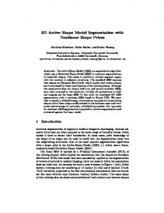
In order to evaluate practically the speed of convergence of type algorithm 15, we consider a set of points in IR2 which are linked to each other with springs. The spring elasticity constants are constants. Analyzing the mathematical convergence properties of a fixed point iterative method with a degenerated iterative function is quite difficult. Hence the aim of this subsection is to understand the interplay between the parameters involved (elasticity coefficients and the properties of the force field). The coordinates of the points are represented by a vector un , and an extreme simplification of the elastic model is represented by a diagonal with an upper and a lower diagonal matrix definite positive A−1 . The function t is defined for all x ∈ IR2 with α = .2 by: ³ ´ x t(x) = −α kxk − 1 . (34) kxk Please note that with the notations introduced in the previous sections, since u0 = 0, we can add div(σ(uk )) to the first equation of algorithm 15 and by taking β = 0, the variational formulation 17 of algorithm 15 is expressed in an equivalent way by: un+1 = un + L−1 (t(I + un )) So the simplified version for the toy 2D problem reads: un+1 = un + A−1 t(I + un ). The three following figures depict the evolution of the springs, the balls with red lines represent the initial configuration of springs and points. The first picture is the configuration after 2 iterations where green squares are the points and blue lines the springs. The second picture is the configuration after 30 iterations and the third one represents the configuration after 3 iterations for a doubled value of the elasticity constants. Please note that the greater the elasticity constants are, the faster the convergence is. Nevertheless, if the elasticity constants are too large no deformations are possible under a reasonable force field.
4
Discussion and conclusions
We end this article with some test cases. The first one consists of transforming a ball into a cube. The space H is approximated by a tetrahedral finite element method of order one, and the parameter τ is taken to be zero. For the numerical example presented here, we have used 2237 tetrahedra and 519 nodes. In Figure 2.1 (a) we have a section of the force field t, the initial template Ω0 is a sphere and is depicted in (b). The convergence for algorithm 15 is reached after ˜ the mesh of the segmented image, is presented in Figure 2 10 iterations and Ω, on the right, and on the left the trace of the segmented image is presented. In what follows, we consider the heart MRI segmentation described in the introduction of this article. In Figure 5 on the left and on the right we respectively 15
2
2
1.5
1.5
1
1
0.5
0.5
0
0
−0.5
−0.5
−1
−1
−1.5
−1.5
−2 −2
−1.5
−1
−0.5
0
0.5
1
1.5
−2 −2
2
−1.5
−1
−0.5
(a)
0
0.5
1
1.5
2
(b) 2 1.5 1 0.5 0 −0.5 −1 −1.5 −2 −2
−1.5
−1
−0.5
0
0.5
1
1.5
2
(c) Figure 4: (a): 4 iter, (b): 30 iter , (c): 3 iter with a doubled value of the elasticity constants
16
display the rigid registration and the segmentation with algorithm 15 of the medical data of the heart of a patient at the end of diastole (see [14] for the data).
Figure 5: Left: rigid registration, right: segmentation with algorithm 15 As we can see in Figure 5, algorithm 15 requires the rigid registration not to be too far from the object we want to detect. When the rigid registration is not so close to the object to be detected, algorithm proposed in the previous sections does not converge towards the correct object. To overcome this difficulty, we propose an extension of the algorithm 15 to the large displacements case. The idea consists of moving the reference configuration at each iteration in process 15. We use the notation introduced in the previous sections. Let τ and β be two positive parameters. We take τ very small, and Ωk will be the sequence of deformed domains. We consider the following algorithm : for uˆk given such that div(σ(ˆ uk )) = 0, find u ˆk+1 verifying : − div(σ(ˆ uk+1 )) = 0 in Ωk ; σ(ˆ uk+1 ) · n + β(ˆ uk+1 − u ˆk ) = tτ (I + u ˆk ) + σ(ˆ uk ) · n Ωk+1 = (I + u ˆk )Ωk .
on ∂Ωk ,
(35a) (35b) (35c)
In what follows, we explain how to extend¡ u ˆk ¢in domain Ωk+1 (ˆ uk is only defined in Ωk ). So, we assume that the sequence Ωk k∈IN remains in a bounded domain O of R3 For u ˆk+1 , solution to the problem (35), we compute u ˘k+1 verifying − div(σ(˘ uk+1 )) = 0 in O \ Ωk ; u ˘k+1 = u ˆk+1 on ∂Ωk ;
(36a) (36b)
u ˘k+1 = 0
(36c)
And we set
½ uk+1 =
on ∂O.
u ˆk+1 u ˘k+1
in in 17
Ωk ; O \ Ωk .
Figure 6: a trace of a heart segmentation without constraint. In Figure 7 the results obtained with algorithm 35-36 are depicted when the registration is not close to the object to be detected. We have proved that a linear 3D elastic segmentation model on vector fields is mathematically well posed and we have proposed a simple algorithm proved to be convergent for computing the solutions. The formulation of the problem as a constraint problem has demonstrated a necessity when working with synthetic images. The algorithm proposed is simple and converges with few iterations and ensures reaching the zero level of the external energy with an arbitrarily large precision corresponding to an arbitrarily small parameter τ in the definition of tτ . The algorithm proposed has been used for segmentation in cardiac MRI and has been showed to be efficient on patient data. If the constraint is not tacken into account for segmentation in cardiac MRI the result suffers some discrepancy (see Figure 6). It is worth mentioning that in numerical simulations the parameter τ is taken to be zero, because it does not significantly change the results. In fact, a nonnegative τ is required for the derivative of t to be negative definite which is a theoretical argument used in theorem 2. A careful analysis of the spectral properties of the derivative Dt in the 2D toy problem (where τ = 0), shows that the operator Dt has a zero eigenvalue, but the sequence of displacement vectors always has a non-zero component belonging to the orthogonal eigenspace where the eigenvalues are negative. A similar study for the force field t issued from GVF technique is beyond the scope of this article. The next step for improving the segmentation process is to eliminate the hy18
(a)
(b)
(c) Figure 7: Left column: registration, right column: segmentation with algorithm 35-36. (a) slices orthogonal to Z axis, (b)-(c) slices orthogonal to X axis and Y axis
(a)
(b)
Figure 8: (a): registration mesh, (b): segmentation mesh
19
pothesis of small displacements. This means in particular that we do not require ˜ while the image is still recoverable. To do this Ω0 to be in a neighborhood of Ω, we propose using non-linear elastic models (see [17]). Acknowledgement This work was carried out during a collaboration with P. Clarysse and Q.C. Pham from the CREATIS laboratory UMR CNRS 5515 INSERM U630 INSA de Lyon. This work has been partially financed with a grant ” 04 3 147 ACI s´ecurit´e informatique: KAA: syst`eme ambiant de s´ecurit´e bas´e sur les connaissances”.
Appendix A Proof. The spectral radius of T can be characterized with the following limit 1
ρ(T ) = lim kT n kBn .
(37)
n→+∞
Let N (²) be such that 1
kT N (²)+1 kBN (²)+1 ≤ ρ(T ) + ².
(38)
We introduce the norm |k·k| defined by N (²)
|kxk| =
X
¡ j=0
1
j ¢j kT xkB . ρ(T ) + ²
An easy calculation leads to ³ |kT k|L(B) = supx6=0
PN (²) j=0
j+1 xk
¢Bj ´
ρ(T )+²
PN (²) j=0
³ = (ρ(T ) + ²) supx6=0
¡kT
j xk B j ρ(T )+² kT j+1 xk
¡kT
PN (²) j=0
¢
¡
B ¢j+1 ´ . j ¡kT xkB¢j ρ(T )+²
PN (²) j=0
ρ(T )+²
Hence we deduce ³ |kxk| − kxkB + |kT k|L(B) = sup
kT N (²)+1 xkB (ρ(T )+²
|kxk|
x6=0
¢N (²)+1 ´ .
Since kT N (²)+1 xkB ≤ |kT N (²+1) k|L(B) kxkB , inequality (38) yields the desired result. Remark 3. This result is still valid for a compact operator in an infinite dimensional Banach space. 20
Appendix B Let γ : H 1 (Ω0 ) → H 1/2 (∂Ω0 ) be the trace application. The space H 1/2 (∂Ω0 ) is equipped with the usual norm (see [12]) kϕk1/2,∂Ω0 =
inf k∇ΦkL2 (Ω0 ) , ∀ϕ ∈ H 1/2 (∂Ω0 ). Φ ∈ H 1 (Ω0 ) γ(Φ) = ϕ
(39)
Moreover, the trace operator has a right continuous inverse: ∃cd > 0, ∀Φ ∈ IHkΦkH 1 (Ω0 ) ≤ cd kγ(Φ)k1/2,∂Ω0 .
(40)
Now let us introduce the following scalar product Z ∀ϕ, ψ ∈ IH1/2 (∂Ω0 ), (ϕ, ψ)1/2,∂Ω0 = where Φ, Ψ are solutions to ½ −∆Φi = 0 in Ω0 , γ(Φi ) = ϕi on ∂Ω0 , .
½
−∆Ψi γ(Ψi )
3 X
∇Φi ∇Ψi dx
(41)
Ω0 i=1
= 0 in Ω0 , 1 ≤ i ≤ 3. = ψi on ∂Ω0 , .
(42)
Please note that the norm induced by the scalar product verifies (ϕ, ϕ)1/2,∂Ω0 = kϕk21/2,∂Ω0 since the optimality conditions for the minimization problem in the definition the norm (39) read: ½ R P3 1 i=1 ∇Φi ∇θi dx, = 0∀θi ∈ H0 (Ω0 ) 1 ≤ i ≤ 3. Ω0 (43) γ(Φi ) = ϕi on ∂Ω0 , For any small positive parameter τ , we can define the penalized external force field in the same way as in the finite dimensional case in subsection 2.2, by tτ (I + u) = t(I + u) − τ (u, ·)1/2,∂Ω0 . If Dt(I + u) is semi-negative definite, then the operator DK τ (u)Φ = Dtτ (I + u)γ(Φ) is surjective from IH onto IH1/2 . For all η ∈ IH1/2 we have to prove the existence of Φ ∈ IH such that Dtτ (I + u)γ(Φ) = η. Let J be the Riez isomorphism which allows us to represent an element q ∈ (IH1/2 )0 by Jq ∈ IH1/2 , which is such that < ·, q >IH1/2 ,(IH1/2 )0 = (·, Jq)1/2,∂Ω0 . We introduce the bilinear form b(ϕ, q) =< Dt(I+u)ϕ, q)IH1/2 ,(IH1/2 )0 −τ (ϕ, Jq)1/2,∂Ω0 , ∀ϕ ∈ IH1/2 , ∀q ∈ (IH1/2 )0 . 21
The bilinear form a(·, ·) is defined by (16) and we consider the problem: find (Φ, λ) ∈ IH × (IH1/2 )0 verifying ∀θ ∈ IH, ∀q ∈ (IH1/2 )0 ( a(Φ, θ) + b(γ(θ), λ) = 0 (44) b(γ(Φ), q) =< η, q > 21 −1/2 . H ,H
Since a(·, ·) is IH-coercive (due to the Korn inequality), it is sufficient to prove the following Brezzi-Babuska condition for the form b(·, ·) (see [5]) ∃ c > 0,
inf Φ ∈ IH kϕkIH1/2 = 1
b(γ(Φ), q) ≥ c. sup 1/2 0 q ∈ (IH ) kqk(IH1/2 )0 = 1
(45)
The derivative Dt(I + u) is semi-negative definite, hence b(γ(Φ), −γ(Φ)) ≥ τ kγ(Φ)k2IH1/2 since Jϕ = ϕ which proves (45) with c = cτd . Remark 4. In the finite dimensional case, we can deal with the L2 (∂(Ω0 )) scalar product instead of the IH1/2 duality product since all norms are equivalent.
Notations
Ker E/F D Di ∇ ∆ P3 div(v) = i=1 Di vi ²i,j = 21 (Di vj + Dj vi 1 ≤ i, j ≤ 3 σ(v) = λT r(²(v))II + 2µ²(v) P3 σ(v) : ²(v) = i,j=1 σij (v)²ij (v)
... ... ... ... ... ... ... ... ... ...
Kernel of a linear operator quotient space Derivative Derivative with respect to the ith variable Gradient Laplacian Divergence Strain tensor Stress tensor Tensor product
Values of parameters for Heart Segmentation
22
E E=200 E=160 ν = 0.1 Eν λ = (1+ν)(1−2ν) E µ = (1+ν)(2) µGV F =0.15 iter=150 100
... ... ... ... ... ... ... ... ...
Young modulus for the right ventricle for the left ventricle Poisson coefficient Lame coefficient Lame coefficient Inverse-diffusion coefficient in GVF Number of iterations Weighting parameter for force field
References [1] G. Aubert & P. Kornprobst, Mathematical Problems in Image Processing. Applied Mathematical Sciences 147 Springer (2002). [2] M. Sermesant, C. Forest, X. Pennec, H. Delignette & N. Ayache, Deformable biomechanical models: Application to 4D cardiac image analysis. Medical Image Analysis 7 Elsevier (2003). [3] T.J. Baker, P. Pebay and J. Pousin, Dynamic Meshing for Finite Element Based Segmentation of Cardiac Imagery, WCCM V - Fifth World Congress on Computational Mechanics, Vienna (2002). http://maths.insalyon.fr/ pousin/paper-wccm.pdf [4] M.S. Berger, Nonlinearity and Functional Analysis Academic press, New-York (1977). [5] Brezzi, F.; Fortin, M.: Mixed and hybrid finite element methods. Springer-Verlag, 1991. [6] P.G. Ciarlet, Introduction `a l’analyse num´erique matricielle et `a l’optimisation, Masson Paris (1982). [7] P.G. Ciarlet, Mathematical Elasticity II, theory of plates, Studies in Mathematics and its Applications 27, Elsevier Amsterdam (1997). [8] L.D. Cohen, Mod`eles d´eformables, In Actes de l’Ecole Thematique ISIS, Marly le Roy, pages 1–20, (1997). [9] H. Brezis, Analyse fonctionnelle, Masson (1985) Paris. [10] B. Faugers, J. Pousin, Variational Asymptotic Derivation of an Elastic Model Arising from a Problem of 3D Automatic Segmentation of Cardiac Images, Analysis and Applications Vol. 2, N 4, (2004) 275-307. [11] D. Gilbarg & N.S. Trudinger, Elliptic Partial Differential Equations of Second Order, A series of Comprehensive Studies in Mathematics 224, Springer-Verlag Berlin Heidelberg New York (1977).
23
[12] P. Grisvard, Elliptic Problem in Nonsmooth Domains, Advance Publishing Program, Pitman Boston London Melbourne (1985). [13] Q.C. Pham, F. Vincent, P Clarysse, P. Croisille & I. Magnin, A FEM-Based Deformable Model for the 3D Segmentation and Tracking of the Heart in Cardiac MRI, Image and Signal Processing and Analysis ISPA 2001, Pula Croatia (2001) 250-254. [14] Q.C. Pham, Segmentation et mise en correspondance en imagerie cardiaque multimodale conduites par un mod`ele anatomique bi-cavits du coeur, Phd Dissertation INPG (2002). [15] J. P. W. Pluim, J. B. A. Maintz, M. A. Viergever Image Registration by Maximization of Combined Mutual Information and Gradient Information IEEE Transaction on Medical Imaging , Vol. 19, N0. 8. (2000) 809-814. [16] J. Fitzpatrick, D. Hill, C. Maurer, Image registration, Handbook of Medical Imaging Vol. 2. SPIE Press (2000) 375-435. [17] Y. Rouchdy, J Pousin , Schaerer,P. Clarysse , A nonlinear elastic deformable for soft structure segmentation. Application to the Heart segmentation in MRI. Submitted to Inverse Problem Journal http://maths.insa-lyon.fr/ pousin/article v2.pdf 2006. [18] Schaerer, Y. Rouchdy, P. Clarysse,B. Hibab, P. Croisille, J Pousin , I.E. Magnin , Simultaneous Segmentation of the Left and Right Heart Ventricles in 3D Cine MR Images of Small Animals. Computers in Cardiology 2005 IEEE publications p. 231-234. [19] C. Xu & J.L. Prince, Snakes, shapes, and gradient vector flow., IEEE Trans. Image Processing, 7,3, (1998) 359–369. Correspondence Professor J´erˆome Pousin Institut C. Jordan UMR CNRS 5042, bat. L. De Vinci, INSA de Lyon, F-69621 Villeurbanne cedex, France
[email protected]
24