A Memory Efficient Architecture of Deblocking Filter in H.264/AVC using Hybrid Processing Order Kyeong-Yuk Min
Jong-Wha Chong
Dept. of Electronic Engineering Hanyang University Seoul, Korea
[email protected]
Dept. of Electronic Engineering Hanyang University Seoul, Korea
[email protected]
Abstract— In this paper, we propose a memory and performance optimized architecture to accelerate the operation speed of adaptive deblocking filter (DF) for H.264/JVT/AVC video coding. With the proposed processing order, we can reduce not only the number of internal buffer but also the size of the internal SRAM. Two 4x4 internal buffer with MUXs and a 32x16 internal SRAM are needed for the buffering operation of DF with I/O bandwidth of 32 bit. The filtering cycles of the proposed DF are 192 clocks in loading/storing and filtering operations. Proposed architecture can be processed in real-time for 1080HD (1920x1088@30fps) at a 70MHz clock frequency.
between vertical and horizontal filtering. One of the major design issues for the implementation of the DF is the reduction of the size of memory for intermediate data. Most of the previous studies in [3]-[10] focused on processing order of 4x4 blocks in a macroblock and data reuse to reduce the size of the internal buffer and the memory bandwidth in [3]-[10]. The processing orders of previous studies in [3]-[10] are categorized by sequential order and hybrid one. According to the processing order of each previous studies in [3]-[10], the architecture has a different type of intermediate buffer and internal SRAM.
Keywords-component; Deblocking filter, H.264/AVC, SRAM, throughput
In this paper, to reduce the operation cycles and the number of internal buffers, a new architecture is proposed by a hybrid filtering order and an efficient scheduling of the internal buffer and SRAM. As the result, the number of total clock cycles of the DF operations is only 192.
I.
INTRODUCTION
Block-based image compression technology is widely used in the previous video coding standards such as MPEG-1, 2 and H.264/AVC[1]. The outstanding features of the block-based compression architectures are simplicity and regularity. As the block-based compression technique have the merits of its implementation, it also makes the blocking artifact from the difference of quantization step values between the blocks. In order to reduce the artifacts from the block-based processing, H.264/AVC has adopted deblocking filter (abbreviated by DF) in [1] and [2]. In order to improve video quality, the DF is used in the encoder and decoder in H.264/AVC. In the encoder side, the efficient motion estimation is available by using a filtered image as a reference picture. On the other hand, in the decoder, the DF improves the decoding video quality. However, as the DF is applied to all of the vertical and horizontal edges of 4x4blocks, a complex computation is required as in [2]. The process of the DF is the most complex part of the H.264/AVC decoder and it consumes one-third of the computational complexity as in [3]. Thus, fast computation of the DF is necessary for real time processing of the H.264/AVC decoder. In the H.264/AVC coding standard, the DF has a vertical and horizontal processing order in a macroblock. These processes have the drawback of large memory size for the intermediate data. First, the processings of filtering for four vertical edges in a macroblock are performed, and they transpose intermediate data from the vertical filterings, and then the processings of filtering for four horizontal edges are becoming processed. These processes have the drawback of large memory size of a macroblock for the intermediate data
978-1-4244-5035-0/09/$26.00 ©2009 IEEE
This paper is organized as follows. In Section 2, the algorithm of the DF is introduced. In Section 3, we propose an efficient architecture in order to improve the waste of cycles. In Section 4, we compare the proposed architecture with the conventional one. Finally, the conclusion is given in Section 5. II.
DEBLOCKING FILTER
A. Boundary Strength of Deblocking filter Because transform coding in H.264/AVC is operated on 4x4-blocks, the DF is applied to the edges of 4x4-blocks in a macroblock. This DF algorithm in H.264/AVC standard is highly adaptive. Adaptivity of the DF is summarized as three different levels, slice, block-edge and sample level. At the slice level, the threshold parameters for filtering are defined by filter coefficient and strength between two macroblocks. At the block edge level, the strength of the filtering dependents on inter/intra predictions, motion vector difference and coded residuals in the 4x4 blocks. At the sample level, whether filter is turned or not is decided for a particular sample to avoid real edge distortion. At the block level, The value of boundary strength (Bs) decides the strength of the DF operation. Bs is associated with each edge of the 4x4 blocks. The selection of Bs depends on inter/intra prediction, different motion vector and coded residuals in the 4x4 blocks along the edge. The Bs can attain five different values, 0, 1, 2, 3 and 4. In the standard mode of filtering with the value of Bs from 1 to 3, the value of Bs reflects the maximum modification of the sample values by
-67-
ISOCC 2009
filtering. In this case, 4-tap filter is used for filtering. When the value of Bs is 0, no filtering is applied. After the values of Bs were decided by the block modes and conditions, the vertical and horizontal edges are filtered. The FIR filter has a simple architecture composed by adders and shifters only.
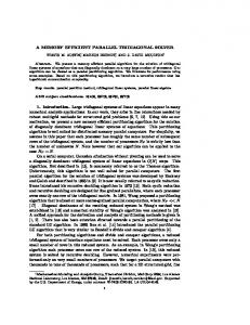
Designs in [5],[6] employ basic sequential order that conforms to the processing order specified by the H.264/AVC standard. Figure (2b) is an improved sequential order which explores certain data reuse. For instance, filtering of edge2 may 1 , which saves memory read/write reuse the result of edge ƻ operations. The DF using hybrid order depicted in the figure
B. Filtering Operation In the H.264/AVC standard, the adaptive DF is applied to the edges of each 4x4 block in a macroblock. Figure (1a) shows the filter operation between two adjacent 4x4-blocks and the processing order of the DF in a macroblock. Figure (1b) shows that 24 vertical edges and 24 horizontal edges must be filtered for a macroblock. In the figure (1a), for the filtering of a vertical edge, two adjacent blocks must be loaded into the (a) Sequential order I
(b) Sequential order II
(c) Hybrid order I (d) Hybrid order II Figure 2. Filtering order of the previous works
(2a) and the figure (2b) filter all of the four edges at the same direction and then change to the other direction. Data reuse takes place only in one direction. Another hybrid order depicted in the figure (2c) and the figure (2d) exploit data dependency between neighboring horizontal and vertical edges, storing the results of intermediate filtering in buffers and writing to memory only when completely filtered.
a) Filtering operation between two 4x4 block
III.
b) Horizontal and vertical filtering over edge on a macroblock Figure 1. Filtering operation of vertical and horizontal edges for one Macro block
8x4 pixel array. However, the filterings of the vertical edges of No.2, 3 and 4 in the figure (1a) require only one additional block, because one block for filtering was already loaded in the 8x4 pixel array. In this order, the DF processes on the four vertical edges and transposes the intermediate data, and then processes on the four horizontal edges. The major drawback of this approach in the standard is that the intermediate data storage is as large as a whole 16x16 macroblock size. C. Analysis of Processing Order of the DF Processing orders which can be classified as sequential and hybrid orders affect the throughput of the DF. In a sequential processing order, the DF filters all of the vertical edges first and then processes all of the horizontal edges. In a hybrid processing order, the DF filters vertical and horizontal edges in a mixed pattern but gets the same final filtered pixel value. Figure 2 shows some processing orders of DF found in the previous studies as in [3]-[10].
PROPOSED ARCHITECTURE
The major design issues for an efficient hardware architecture of the DF are how to reduce the memory bandwidth, the number of intermediate buffers and the size of internal SRAM. Especially, the most important thing is the scheduling of the intermediate buffer for 2-dimensional operation between vertical and horizontal filterings in a macroblock. Proposed architecture can minimize the processing cycles for 1 macroblock and can reduce the size of internal SRAM and intermediate buffer. The proposed DF is composed of seven MUXs for the data interchange among intermediate buffer and internal SRAM and 1D reconfigurable filter. A. Processing Order Figure 3 shows the proposed filtering order that produces the same result as specified by the H.264/AVC standard. In figure 3, the data from the blocks H1~H4 and the blocks V1~V4 have been vertically and horizontally filtered as a part of the filtering process for the above and the left macroblocks, respectively. The processing order is denoted by the numbers inside the thick circles in figure 3. First, we process the horizontal filtering of the vertical edge between V1 and B1 blocks. Second, the operation of the horizontal filtering is performed on the vertical edge between B1 and B2 blocks. And then, the operation of the vertical filtering is performed on the
-68-
ISOCC 2009
horizontal edge between H1 and B1 blocks. Note that the B1 block used in the third step is an intermediate data from the horizontal filtering of the vertical edge between B1 and B2 blocks. This interleaved approach of horizontal and vertical filterings is repeated for each 4x4 block in a raster scan order by the 4x4-block line, like the numbers shown in figure 3. In an interleaved approach, the intermediate data will be used immediately.
uses to store the intermediate pixel value when applying the proposed hybrid scheduling.
Figure 4. Proposed hardware accelerator for deblocking filter
Figure 3. Filtering order used in the proposed architecture
B. Architecture of Proposed DF The proposed architecture has two buffers that can store the intermediate block generated from the filtering order. Thus we can save the memory access and buffer to be required to process the left, the top, and the right edge in a 4x4 block. Therefore, we need only four 4x4 blocks above the current 4x4-block line denoted as H1~H4 rather than a whole macroblock in the conventional data flow. We have derived the filtering order in the figures 3, and 6, from the proposed hybrid scheduling method. Each number in thick circle represents the filtering order of vertical and horizontal edges as in each figure. And these numbers in these figures are the sequence of event in a macroblock. So we can easily examine the order of filtering in a macroblock. C. Proposed 1D Reconfigurable Filter and Internal Buffer To speed up the filtering operation, the proposed FIR filter adopts a parallel architecture. In the datapath of strong and normal filter, multiple input adders are implemented by carrysave adder tree to speed up the addition. Only one clock is assigned for the filtering. The internal SRAM is used as a 4x4block buffer, and its size is only 32x16. The internal buffer
Figure 5. Architecture of the proposed 4x4 register block
It contains the 2x4x4 pixel values. The 4x4 register is designed with flip-flop to process transposed block filtering as shown in figure 5. By means of the proposed transposition circuit, the horizontal edge filtering is processed in the same way as vertical edge filtering. The detailed operation for filtering of a macroblock will be stated as follows. In the first step, as the number ̺ 1 in figures 3 and 6, V1 block is loaded by 32 bits from the external memory to the internal buffer A. When one 4x4 block(V1) and 1 line of B1 block are loaded from the external memory, 1D deblocking filter is started. Then the intermediate data from the horizontal filtering of the vertical edge between V1 and B1 blocks is stored into the buffer B shown as ̺ 2 in figures 3 and 6. After the first filtering, B2 block is loaded
Figure 6. Detailed timing map of proposed deblocking filter with a 4x4 line
-69-
ISOCC 2009
from the external memory. At the same time, the second filtering is started on the horizontal edge of B1 and B2 blocks. After the second filtering, the intermediate data from B2 and B1 are stored and refreshed in the buffers A and B, respectively. The third filtering is depicted as ̺ 3 in figures 3 and 6. The H1 block is loaded from the internal SRAM or the external memory. In the same way, B1 block is transposed and filtered with H1 block. After the vertical filtering over H1 block and B1 block, the output from the H1 block is pushed to the output port. The B1 block is stored in the internal SRAM in order to be used as the upper data in second 4x4-block line. In the figure 6, the timing map of the filtering operation is depicted. “V1_1” in figure 6 means the first line of V1 block. The operation cycles of a 4x4-block line with luminance data is 32 clocks. Then, the number of cycles of the operation of 16x16 macroblock for the luminance data is 32x4 = 128 cycles. The operation cycles of a 4x4-block line with the chrominance data is 16 clocks like figure 6. The evaluated cycles are 128 (32 x 4) cycles for the luminance block and 64 (16 x 2 x 2) cycles for the chrominance block based on the proposed architecture for high throughput deblocking filter. In sum, we need 192 (128 + 64) cycles to filter horizontal and vertical edges of the luminance and the chrominance blocks in a macroblock. IV.
SIMULATION RESULTS
Table 1 shows the comparison between the proposed DF and previous architectures. The proposed one needs 192 cycles to filter a macroblock and two 4x4 internal buffer with MUXs. Compared with the existing approaches in [3]-[10], our architecture could achieve the smallest processing cycles per macroblock and the smallest size of internal buffer. By using the proposed architecture, we can save about one-half of the processing cycles per macroblock. The proposed DF was implemented with Verilog-HDL and Synopsys Design CompilerTM with 0.18um design rule of Samsung ElectronicsTM and verified the functions with ModelSimTM. Therefore, this processing capability can decode 1080HD with real-time process (1920x1088, i.e. 8160MB/frame) for 4:2:0 format when the operating frequency is 70MHz.
V.
CONCLUSION
We proposed an efficient architecture of DF to accelerate the speed of filtering operation for H.264/JVT/AVC video coding in this paper. The proposed DF executes the filtering operations with only 192 cycles for 1 macroblock. Only a 2x4x4 internal buffer and 32x16 internal SRAM have been adopted for the buffering operation of DF with I/O bandwidth of 32 bits. As a result, we can reduce the processing cycles and improve the system throughput. The proposed architecture can be applied to a high performance video system such as video telephony, video conferencing, video streaming and many others. REFERENCES [1]
Final Draft International Standard of Joint Video Specification (ITU-T Rec. H.264/ISO/IEC 14496-10 AVC), Mar. 2003. [2] P. List, A. Joch, J. Lainema, G. Bjøntegaard and M. Karczewicz, “Adaptive de-blocking filter”, IEEE Trans. Circuits Syst. Video Technol., vol. 13, pp. 614-619, Jul. 2003. [3] S. C. Chang, W. H. Peng, S. H. Wang and T. Chiang, “A platform-based bus-Interleaved architecture for de-blocking filter in H.264/MPEG-4 AVC,” ” IEEE Trans. on Consumer Electronics, vol. 51, No 1, pp. 249255, Feb. 2005. [4] M. Sima, Y. Zhou and W. Zhang, “An efficient architecture for adaptive de-blocking filter of H.264/AVC video coding” IEEE Trans. on Consumer Electronics, vol. 50, Issue 1, pp. 292-296, Feb. 2004. [5] S.Y. Shih, C. R. Chang, and Y. L. Lin, “An AMBA-complient deblocking filter IP for H.264/AVC,” in Proc, IEEE Int. Symp. Circuits Syst., May 2005, vol. 5, pp. 4529-4532. [6] Y.W. Huang, T. W. Chen, B. Y. Hsieh, T. C. Wang, T. H. Chang, and L. G. Chen, “Architecture design for deblocking filter in H.264/AVC,” in Proc. IEEE Int. Conf. Multimedia EXPO., Jul. 2003, vol. 1, pp.693-696. [7] B. Sheng, W. Gao, and D. Yu, “An implementation architecture of deblocking filter for H.264/AVC,” in Proc, Int. Conf. Image Process., Oct. 2004, vol. 1, pp.24-27. [8] C. C. Cheng, T. S. Chang, and K. B. Lee, “An in-place architecture for the deblocking filter in H.264/AVC,” IEEE Trans. Circuits Syst. II, Exp. Briefs, vol. 3, no. 7, pp. 530-534, Jul. 2006. [9] T. M. Liu, W. P. Lee, T. A. Lin, nd C. Y. Lee, “A memory-efficient deblocking filter for H.264/AVC video coding,“ in Proc. IEEE Int. Symp. Circuits Syst., May 2005, vol. 3, pp. 2140-2143. [10] K. Xu, C. S. Choy, “A five-stage pipeline, 204 cycles/MB, single-port SRAM-based deblocking filter for H.264/AVC,” IEEE Trans. Circuits Syst. Video Technol., vol. 18, pp. 363-374.
TABLE I COMPARISON OF ARCHITECTURE AND PROCESSING CYCLES FOR THE DF IN H.264/AVC
Processing Order Architecture RAM size(bit) & type
Internal buffer size(bit) Technology(nm) Gate Count(k) Processing Cycles per MB
[5]
[6]
[7]
[8]
[9]
sequential Nonpipelined
sequential Nonpipelined
hybrid Nonpipelined
hybrid Nonpipelined
1x160x32 (two-port)
2x80x32 (two-port)
hybrid Nonpipelined 1x64x32 2x96x32 (two-port)
16x32 (two-port)
1x160x32 (single-port)
256 (2x4x4, with MUX) 0.25 18.77 646
512 (4x4x4, with MUX) 0.25 20.66 614
256 (2x4x4, with MUX) 0.25 13.41 300
512 (4x4x4, with MUX) 0.18 19.64 250
none 0.25 24 446
-70-
[10] hybrid pipelined 2x96x32 2Nx32 (single-port) 896 (7x4x4,with MUX) 0.18 21.4 204
Proposed Architecture hybrid Nonpipelined 16x32 (two-port) 256 (2x4x4, With MUX) 0.18 12.3 192
ISOCC 2009