A Pseudo-Differential Comparator-Based Pipelined ADC with Common Mode Feedforward Technique Li Ding, Sio Chan, Kim-Fai Wong, Sai-Weng Sin, Seng-Pan U1, R.P.Martins Analog and Mixed Signal VLSI Laboratory (http://www.fst.umac.mo/lab/ans_vlsi) Faculty of Science and Technology, University of Macau, Macao, China E-mail –
[email protected] (1 – Chipidea Microelectronics, Macao, China - E-mail -
[email protected]) (2 - on leave from Instituto Superior Técnico / TUL, E-mail -
[email protected]) 2
Abstract—Comparator based switched capacitor technique is a new topic because of its suitability of scaling and its inherent low power consumption. Since CBSC technique suffers from the overshoot due to the comparator delay, this paper gives a detailed analysis on the overshoot signal, and a common mode feedforward circuit is proposed to correct the overshoot error. A 10-bit 100MS/s pseudo differential pipelined ADC is presented to verify the idea. The SNDR of the pipelined ADC is 55dB.
I.
INTRODUCTION
The design of opamp in scaled CMOS technology is becoming increasingly difficult. Although parasitic capacitances are reduced and allowing higher speed, the decrease in power supply voltage limits the signal swing, and output resistance. To design a high performance opamp with low power consumption is a big challenge [1]. A new comparator based switched capacitor technique was proposed in [1]. This new technique can eliminates the need for high gain power-hungry opamps. It also consumes mostly the dynamic power and it is compatible with the usual switched capacitor (SC) circuits. In SC circuits, what we concern is the charge transfer in capacitors. Traditionally, we use an opamp to force the virtual ground condition to do the charge transfer, but for the CBSC, we use a comparator to sweep the virtual ground condition, the comparator determines when to shut down the charging current source. But the comparator and the logic gates have propagation delays; which will cause an overshoot in output signal. In pseudo-differential pipelined ADC application, the overshoot is a common-mode error. We have to design a common mode feedback circuit to correct the error, otherwise the common mode error will accumulate and saturates the subsequent stages. In this paper, a pseudo differential pipelined architecture is described in detail, and a comparison between some previously common mode feedback and error averaging technique is presented. A detailed analysis on the overshoot is given. And finally, this paper proposes a common mode
978-1-4244-2342-2/08/$25.00 ©2008 IEEE.
feedforward solution which can avoid common-mode accumulation in pseudo differential pipelined ADC. II.
COMPARATOR BASED CHARGE TRANSFER
This section describes the CBSC gain stage charge transfer. The charge transfer phase is divided into three phases, the preset phase, the coarse transfer phase and the fine transfer phase. The CBSC gain stage is shown in Fig.1 (a). After the sampling capacitors C1 and C2 sample the input signal, the output is pulled to ground. It is the preset phase. In preset phase, the positive input of the comparator is pulled down away from the virtual ground condition. Then the current source E1 is activated to charge the capacitor network and sweep the virtual ground. Once v+ is equal to the vcm which is the virtual ground condition, the E1 is shut down and E2 is activated. Because E1 is a large current source, the overshoot in coarse phase is big. A fine phase is added to sweep the virtual ground condition again to keep the final overshoot small. The time is shown in Fig.1 (b). [1]
Fig.1 (a) CBSC gain stage (b) Charge transfer timing diagram [1] III.
OVERSHOOT ANALYSIS
From the operation of the CBSC gain stage charge transfer, we have known that the final overshoot is caused by the comparator decision delay and the logic gate propagation delay. The delay time lets the fine current source not be shut
276
down immediately; additional charges are pulled out from the capacitor network. Since the overshoot is caused by the current source, the output resistance of the current source will affect the overshoot. As a result, the final overshoot can be divided into three kinds of errors: signal independent error, signal dependent error and the high order error. Most of the overshoot error is the signal independent error which relates to the delay time td, fine current source I2 and capacitance. The signal dependent error is the gain error which is due to the output resistance of the current source and will not affect the linearity of the gain stage. The high order error is due to that the output resistance is not a constant and does affect the linearity of the gain stage. Neglecting the high order error, the signal independent error can be equivalent to the input referred offset for the opamp based case.
Vos =
C1 I2 td C1 + C2 CE
(1)
where CE is the equivalent capacitance of the capacitor network, td is the total propagation delay time. The effective open loop gain is
A=
CE Ro C1 td C1 + C2
(2)
where Ro is the output resistance of current source I2.[1] When CBSC technique is applied to the pipelined ADC, the overshoot must be minimized. Otherwise, the overshoot will be amplified by the gain of the MDAC and accumulated throughout the pipelined ADC. In last several stages, the overshoot can be amplified to the full scale, and the pipeline will not work. In order to cancel the overshoot, there is a technique proposed earlier called error averaging method. In that technique, the whole charge transfer phase is divided into two phases. In the first phase, a normal charge transfer is done, in the second phase; all the capacitors change their polarities. Due to the polarity change, the overshoot is in the opposite direction. By averaging the two outputs, the overshoot can be cancelled [2]. However, this method can only eliminate the signal independent error in overshoot. It does not contribute to the gain error. And this method will low down the ADC speed by 2 because it needs sample and transfer twice in one period. Since the overshoot can be referred to the input, we can consider the overshoot as the input referred common mode error; the error averaging method can not detect and correct
that error. In the pipeline case, the error will be passed to the next stage and accumulated. There is another method presented in [1] to minimize the overshoot. In coarse transfer phase, the negative input of the comparator is connected to a lower voltage reference so that the overshoot in coarse phase is small, then a small fine current source can be used to discharge the capacitor network. And the final overshoot keeps small because of the smaller I2 has been applied. However, in high speed condition, the overshoot in coarse phase will be very large, which means we have to apply a more low voltage reference on the negative input of the comparator. This method will affect the signal swing. Since during the preset phase, the positive input of the comparator should be pulled down to become less than the negative input. When the negative input becomes lower, the signal swing should be decreased to satisfy the condition that the positive input is less than the negative input during the preset phase. IV.
COMMON MODE FEEDFORWARD TECHNIQUE
Since the signal independent quantity dominates the overshoot, we want the overshoot to become common mode error. Then we can design a common mode feedback to correct it with other common mode errors. In fully differential case, the comparator is a differential comparator, the positive signal and the negative signal are opposite, so the overshoot acts as the differential offset. The differential offset will affect the decision of the sub-ADC. The total differential offset due to the overshoot in all the stages can be referred to the input and act as the offset in digital code. And the differential offset will not be accumulated but will limit the output swing. In the pseudo differential case, the operation of the positive part circuit and negative part circuit are the same but dealing with a differential signal. So the overshoots have the same direction and acts as the common mode error. The common mode error will be accumulated if it is not cancelled. It is easier to cancel the common mode error than the differential offset, so we need to design a common mode feedback circuit. In practical, the common mode error is also due to the switch charge injection, but the overshoot dominates the common mode error. The common mode error due to the overshoot can be considered as the input referred common mode error. If we want to integrate the common mode correction phase in the charge transfer phase rather than adding an additional phase, we have to shift the virtual ground condition to another level. Based on this idea, there is a common mode feedback proposed for CBSC sigma delta modulator shown in Fig.2. [3]
Fig.2 Common mode feedback for CBSC sigma delta modulator
Fig.3 Block diagram of CMFF
277
Fig.4 Pseudo differential CBSC MDAC with proposed CMFF The output of the common mode feedback is connected to the negative input of the comparator. In previous sample, the common mode feedback circuit senses the output common mode in transfer phase, and stores the common mode signal. In present sample, the stored signal is fed to the negative input of the comparator. It is equivalent to change the virtual ground condition simultaneously in both the positive part and the negative part. So that if there is input referred common mode error, since the virtual ground condition changes, output common mode can be corrected. However, this common mode feedback uses the previous sample’s common mode signal to feed to present sample, which will induce a correction delay. When the input signal is near to Nyquist rate, the common mode error differs from each sample. If there are some signal dependent common mode errors, they will be amplified by the positive feedback. For example, if the common mode error of previous sample is lower than the ideal value, then the output of CMFB is higher than the ideal value, however, if the common mode signal of present sample is higher than the ideal value, the feedback is positive. And the common mode feedback will be unstable. So we have to design a common mode feedback which can correct the common mode error instantaneously, which means the CMFB circuit senses the common mode value of the present sample and feedback to the present sample. In CBSC pseudo differential pipelined case, the common mode error always appears after the charge transfer phase finished because the overshoot always appears after the fine transfer phase. So in usual applications, it is impossible to design an instantaneous CMFB. However, for the pipeline application, we can design such an “instantaneous CMFB circuit” using feed forward technique. In pipeline ADC, every output signal will be processed again in the next stages. So we can sense the common mode signal of a sample in the previous stage, and feed it to the current stage it being processed. For example, we first sense the output common mode signal in stage 1 and use that signal to feed into stage 2.
Then the common mode signal is always sensed and fed to the same sample. There is no correction delay and therefore no positive feedback. Based on this idea, we have designed a CMFF (Common Mode Feed Forward) circuit using SC technique. The block diagram of the proposed CMFF is shown in Fig.3. The circuit of a MDAC with proposed CMFF is shown in Fig.4. In this CMFF circuit, we sense the input common mode signal in the sample phase and feed the signal to the negative terminal of the comparator during the transfer phase. Since the input common mode signal of the current stage is the same as the output common mode signal of the previous stage, we can integrate the CMFF circuit into a pipeline stage. The output of CMFF circuit can be written.
Vcmff =
2C1 + C2 C1 Vcm − Vin _ cm C1 + C2 C1 + C2
(3)
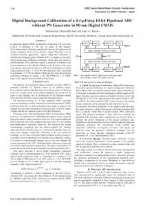
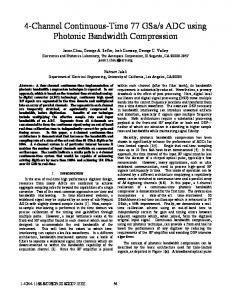
The output of CMFF is connected to the negative terminal of the comparator so that we can adjust the virtual ground condition. Since we adjust the virtual ground condition on the positive and negative part simultaneously, the differential signal does not change if neglecting the signal dependent part and high order part in overshoot, only the common mode signal is changed. With this method, the common mode error will not be accumulated in the pipeline ADC application. SIMULATION RESULT To verify the proposed CMFF technique, a 10-bit, 1.2V, 1.5b/stage, 100MS/s pipelined ADC was designed using 90nm CMOS process. The input swing is 1.2V. Fig.5 shows the unstable results of previously proposed CMFB circuit in Fig.2. Although the common mode signal is stable in the first stage, it oscillates in 6th stage. When the common mode signal is high, in the next sample, it is over corrected, so the oscillation exists in the common mode signal. Fig.6 shows the common mode signal of the last stage using proposed CMFF circuit. The common mode signal can be controlled without oscillation and within the range of 600mV ± 50mV . The
278
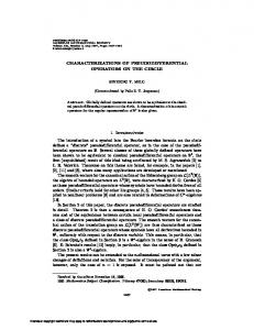
SNDR of pipelined ADC is 55dB when the input frequency is 26.56M. The FFT spectrum is shown in Fig.7. The INL is +0.9/-0.9 LSB, the DNL is +0.3/-0.7 LSB, shown in Fig.8. The SFDR is 62dB. The power consumption is 30mW.
INL
DNL
Fig.5 (a) Common mode signals in first stage using CMFB in Fig.2; (b) Common mode signal in 6th stage using CMFB in Fig.2
Fig.8 Simulation of INL & DNL CONCLUSION In this paper, a 1.2V 10-bit, 1.5b/stage, 100MS/s pseudo differential pipelined ADC with switched capacitor common mode feedforward circuit using CBSC technique was designed. The output common mode signal of each stage can settle within the range of 600mV ± 50mV . The common mode error is not accumulated. The SNDR is 56.5dB when input frequency is 26.56MHz. The SFDR is 62dB. The INL is +0.9/-0.9 LSB, the DNL is +0.3/-0.7 LSB. Total power consumption is 30mW. ACKNOWLEDGMENT
Fig.6 Stabled output common mode signal using proposed SCCMFF
This work was financially supported by University of Macau under the Research Grant with Ref no: RG 058/0607S/MR/FST.. REFERENCES [1]
[2] [3]
[4] [5]
Fig.7 FFT spectrum when fin=26.56MHz
[6]
279
Fiorenza, John K. et al. “Comparator-Based Switched-Capacitor for Scaled CMOS technologies”, IEEE Journal of Solid-State Circuits. vol. 41, No. 12, Dec. 2006, pp. 2658-2668. Chia-Liang Lin, United States Patent, “Error Averaging Comparator Based Switched Capacitor Circuit And Method Thereof”. Dusan Prelog, “Cascade delta-sigma modulator with pseudodifferential comparator-based switched capacitor gain stage”, Analog Integr Circ Sig Process (2007) 51: 201-206. Akira Matsuzawa, “Trends in high speed ADC design”, Department of Physical Electronics, Tokyo Institute of Technology Stephen, H. Lewis and Paul, R. Gray, “A pipelined 5-Msample/s 9-bit Analog to Digital Converter”, IEEE Journal of Solid State Circuits, vol. sc-22, No.6, Dec. 1987. Philip E. Allen and Douglas R. Holberg, "CMOS Analog Circuits Design", 2nd Edition, Oxford Univertisy Press, Inc., 2000.