analog interface circuit produces a wide range of DC and AC voltages needed .... were also designed to provide accurate probing voltages (car- riers) necessary ...
A Standalone Programmable Signal Processing Unit for Versatile Characterization of MEMS Gyroscopes Alexander A. Trusov, Ilya Chepurko, Adam R. Schofield, and Andrei M. Shkel MicroSystems Laboratory, Mechanical and Aerospace Engineering Department, University of California, Irvine, Irvine, CA, USA {atrusov, ichepurk, adam.schofield, ashkel}@uci.edu platform for capacitive micro-machined gyroscopes and other dynamic MEMS.
Abstract—This paper reports a stand-alone signal processing and control unit designed to provide flexible characterization of MEMS vibratory gyroscopes. The unit consists of a programmable 32-bit 150 MIPS DSP controller, 16-bit 1 MSPS digital-to-analog and 18-bit analog-to-digital interface circuits, and signal conditioning electronics. The multi-channel analogto-digital interface is optimized for detection of small electrical signals typical for MEMS devices. Digitally controlled conditioning of analog signals allows for high-resolution differential digitization of a wide range of detection signals. The digital-toanalog interface circuit produces a wide range of DC and AC voltages needed for actuation and detection in gyroscopes; a single 5 V supply is used to power the board. The DSP controller allows easy MATLAB/Simulink programming and execution-time data exchange. Performance of the board was experimentally characterized using an anti-phase driven rate gyroscope with multi-degree of freedom sense mode. Using 16-bit conversion, the measured capacitance-change equivalent resolution is 27 aF/√Hz . Due to its flexible architecture, the unit is easily customizable for stand-alone and computer controlled operation of a variety of dynamic MEMS.
II.
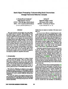
The main hardware components of the proposed platform are a programmable DSP controller, digital-to-analog and analog-to-digital interface circuits equipped with signal conditioning analog electronics, see Fig. 1. The unit was assembled using off the shelf components on a single 112 x 87 mm six-layer PCB. Below we discuss design and implementation of the major circuit blocks and choice of particular components. The main properties of the unit are summarized in Table I. A. Processor A highly integrated Texas Instruments TMS320F2812 single-chip DSP controller was chosen for the board due to its performance/cost efficiency. This DSP has a maximum internal frequency of 150 MHz (i.e., 6.67 ns cycle time) stabilized by a 30 MHz external quartz resonator, and is equipped with 128 K x 16 Flash memory, 18 K x 16 SingleAccess RAM (SARAM). A 16-bit bus with independent data and address transmission lines interfaces the processor with on-board DACs and ADCs. A Serial Peripheral Interface (SPI) and discrete glue logic is used to digitally control potentiometers in the independent analog signal conditioning circuits. The board is linked to a host computer for execution-time data exchange and adjustment of signal processing parameters using an external RS-232C transceiver and an internal Serial Communication Interface (SCI). Programming of the processor is done using a JTAG port.
I. INTRODUCTION Discrete bench-top instruments such as dynamic signal analyzers and lock-in amplifiers are often used for initial structural and Coriolis characterization of micro-machined gyroscopes [1-2]. However, this approach is not practical for stand-alone field-testing of prototypes and does not allow fast and flexible evaluation of different actuation, detection and control algorithms. General-purpose Digital Signal Processing (DSP) systems such as dSPACE [3] and National Instruments Compact RIO [4] can provide a powerful control solution, but have limited portability, are costly and not optimized to interface capacitive MEMS. Custom made integrated and Printed Circuit Board (PCB) level electronics are commonly used for stand-alone operation of gyroscopes [57]; however, change of operational parameters or signal processing and control algorithms often involves circuit redesign and reassembly with different electrical components. In this paper, we report an easily programmable and computer-interfaced yet compact signal processing and control
1-4244-1262-5/07/$25.00 ©2007 IEEE
ELECTRONICS DESIGN
B. Digital-to-analog Interface Circuit The purpose of the digital-to-analog interface circuit is to convert the digital signals generated by the processor into analog waveforms to control gyroscopes and to provide connectivity to external measurement equipment. Based on the high-speed 1 MSPS 16-bit digital-to-analog converter (DAC) TI DAC8820, three types of digital-to-analog interface circuits with different analog signal conditioning were incorporated on the board.
244
IEEE SENSORS 2007 Conference
Figure 1. Block diagram of the main hardware components
channel to convert the analog voltage difference to the digital code with a sampling rate up to 1 MSPS.
Two identical but independent actuation channels were designed in order to accommodate gyroscopes with multidegree of freedom drive modes. Each of the channels consists of a DAC and an additional circuit, which amplifies the generated analog signal and adds a digitally controlled DC bias. These control channels are able to output arbitrary waveform actuation voltages in the range from 0 to ±100 V.
D. Power Handling A single +5 V stabilized external DC voltage source powers the board. All other voltage levels necessary for operation are formed on the board by the dedicated power converters. To power the analog amplifiers, an additional –5 V voltage is generated onboard. A pair of –100 and +100 V is also generated to power the high-voltage amplifiers in the control voltage channels. An additional +1.9 V is used to power the DSP core, and +3.3 V is used for the digital circuits.
Two additional arbitrary waveform low-voltage (–5 to +5 V) channels each based on a simple buffer at the DAC output were also designed to provide accurate probing voltages (carriers) necessary for detection of motion in dynamic microstructures. A separate group of DAC channels was implemented to enable connectivity of the DSP board to external measurement equipment, such as dynamic signal analyzers, for debugging of algorithms and monitoring of experiments in real time. In these channels, the DACs are followed by high quality four-pole Low-Pass Filters (LPF) to suppress the sampling rate signal. The output signals range from –5 to +5 V.
III.
EXPERIMENTAL DEMONSTRATION
In this section we report preliminary characterization of both drive and sense mode functionality of the board with a MEMS gyroscope using electromechanical amplitude modulation (EAM) detection technique, see, for example, [8].
C. Analog-to-digital Interface Circuit Capacitive sensing of drive and sense mode vibratory motion in gyroscopes is typically based on measuring the current induced by the relative motion of capacitive electrodes. To accurately digitize pick-up currents from microgyroscopes, three independent channels were designed and implemented each based on a three-stage fully differential trans-impedance amplifier and a high speed 18-bit ADC.
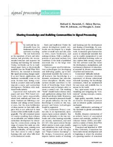
A. Hardware and Software Configuration Fig. 2 shows a photograph of a fully assembled signal processing unit and highlights its main components. The ADCs were configured for 16-bit conversions. A MATLABbased Graphical User Interface (GUI) was developed for the real-time control of the trans-impedance gains, value of the DC component of the driving voltage, as well as amplitudes
The three amplification stages are based on TI THS4141 high-speed fully differential amplifiers with 84 dB common mode rejection. The first stage converts the difference of the input currents into a voltage difference across its two outputs with a digitally controlled trans-impedance gain of 100 – 110 kΩ. The second stage is a fully differential two-pole antialiasing LPF with the –3 dB cutoff frequency of approximately 50 kHz. The last stage is a variable gain voltage amplifier. The gain is defined by Digitally Controlled Potentiometers (DCP) AD5290 and can range from 0 to 20 dB. A high-speed ADC TI ADS8482 was used in each detection
TABLE I.
MAIN OPERATIONAL PARAMETERS
DSP controller TI TMS320F2812 ADC and DAC conversion update rate 2 DAC AC carrier channels 2 DAC AC+DC actuation channels 3 DAC monitor channels 3 differential ADC with transimpedance amplifiers
245
32-bit 150 MIPS 100 kHz 10 Vp-p, 0.15 mV step ±100 V, 0.8 mV step 10 Vp-p, 0.15 mV step 1—10 MΩ gain, 18-bit conversion
Figure 2. A photograph of an assembled controller board with a packaged gyroscope.
and frequencies of the AC driving and carrier voltages. The interface can be easily modified to control any run-time variables.
CDIP-24 package and tested in atmospheric pressure (drive mode-quality factor was approximately 300, sense-mode effective quality factors were approximately 40).
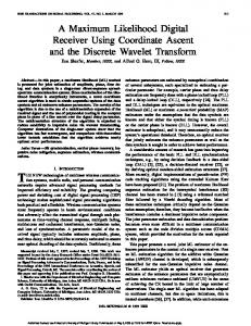
B. Test Device An anti-phase driven rate gyroscope with multi-degree of freedom sense mode [9] was used for the experiments. The gyroscope’s drive mode consists of two coupled frames driven into anti-phase resonance using a common lateral comb drive electrode in the center of the device. Two separate 2-DOF sense mode resonators are located inside of the drive mode decoupling frames. The drive mode resonant frequency is designed to be in-between the 2-DOF sense mode resonant frequencies for robust off-resonant operation and anti-phase detection of the input angular rate. Fig. 3 shows an SEM of a device fabricated in-house using an SOI process [9]. The gyroscope was packaged and wire-bonded in a
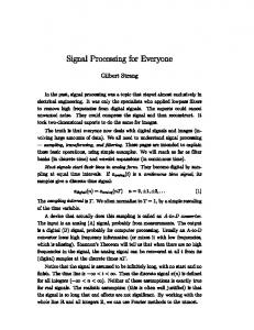
C. Drive Mode Detection In order to actuate the anti-phase motion in the drive mode of the gyroscope, a driving voltage was applied to the central anchored lateral comb electrode. The drive voltage consisted of a 37.5 V DC bias and an AC component at the 1.568 kHz resonant frequency of the device. Using the realtime computer graphical user interface, the amplitude of the AC driving component was adjusted to 14.75 V to achieve the vibration with a nominal 6 µm amplitude. A 5 V AC carrier voltage at 20 kHz frequency was applied to the movable mass of the gyroscope to enable EAM detection of motion. Anti-phase motion of the gyroscope’s decoupling frames was detected using drive-mode parallel plate detection capacitors. The pick-up currents from the anchored electrodes were amplified using the on-board three-stage differential transimpedance amplifier and digitized. Fig. 4 shows Power Spectral Density (PSD) of the drive-mode pick-up signals for the cases of single-sided and fully differential capacitive detection. The single-sided detection signal contains feedthrough of drive and carrier AC voltages, as well as multiple informational sidebands inherent to parallel plate detection of sinusoidal motion [8]. Differential detection with independently tuned gains has several practical advantages. Unwanted parasitic feedthrough of the drive AC signal was suppressed by almost 20 dB. Also, the white noise floor was improved by approximately 10 dB. Most importantly, the 20 kHz carrier signal was suppressed by more than 30 dB to the level below the main informational sidebands, thus improving the useable dynamic range.
Figure 3. SEM of the gyroscope used for the experimental evaluation of the board.
In the described experiment, the nominal parallel plate sense capacitance of the gyroscope’s drive mode was 0.22 246
Figure 4. Experimentally measured PSD of the drive-mode modulated pick-up signal during 6 µm amplitude vibrations.
Figure 5. Experimentally measured PSD of the sense-mode modulated pick-up signal during sinusoidal rotation.
pF. During the 6 µm amplitude vibration, the main harmonic of the parallel plate capacitance change had an amplitude of 0.15 pF [8]. For the tested gyroscope, the measured displacement-equivalent resolution was 1.13 nm/√Hz. By normalizing to the gyroscope’s parameters, capacitance-change equivalent resolution of the board with 16-bit ADC was derived to be 0.027 fF/√Hz.
grant CMS-0409923. The tested gyroscope was fabricated in the UC Irvine Integrated Nanosystems Research Facility (INRF). Experimental characterization was performed at the UC Irvine Microsystems Laboratory. The authors would like to acknowledge Lynn E. Costlow and Cenk Acar of BEI Technologies for the useful discussions, and Jeff Parrott for the help with digital photography.
D. Sense Mode Detection Preliminary characterization of the Coriolis detection functionality of the board was also performed using the antiphase driven gyroscope [9]. Actuation of the drive mode vibration was done as in the previously described experiments; the detection channels were switched from the drive mode to the two differential sense mode capacitors inside one of the decoupling frames. The board was mounted on a rate table, which was configured to produce sinusoidal rotation of a fixed amplitude and frequency. Two different experiments were performed: 3.6 deg rotation at 5 Hz frequency, and 7.2 deg rotation at 2.5 Hz frequency. In both cases, the amplitude of the applied sinusoidal angular rate was 18 deg/s.
REFERENCES [1]
[2]
[3]
[4]
[5]
Fig. 5 shows PSD of the sense-mode pick-up signal around the left informational sideband. In each experiment, the signal contains two angular rate-modulated sidebands, and a 40 deg/s uncompensated quadrature. The demonstrated resolution is sufficient for scale factor characterization of gyroscopes in various temperature and pressure conditions; it can be improved by using the built-in 18-bit conversion capability, performing demodulation of the EAM signal digitally before outputting analog measurements, increasing the maximum trans-impedance gains, and increasing amplitude and frequency of the carrier AC voltage.
[6]
[7]
[8]
[9]
ACKNOWLEDGMENT This work was supported by BEI Technologies contract BEI36974, UC Discovery program ELE04-10202, and NSF
247
Huikai Xie and Garry K. Fedder, “Fabrication, characterization, and analysis of a DRIE CMOS-MEMS gyroscope,” IEEE Sensors Journal, vol. 3, pp. 622-631, October 2003. Cenk Acar and Andrei M. Shkel, “Inherently robust micromachined gyroscopes with 2-DOF sense-mode oscillator,” IEEE Journal of Microelectromechanical Systems, vol. 15, pp. 380- 387, April 2006. dSPACE Inc. (2007) Solutions for control – catalog 2007. [online]. Available: http://www.dspace.de/shared/data/pdf/catalog2007/ dSPACE_Catalog_2007.pdf National Instruments. (2007) CompactRIO – real-time embedded controllers. [online]. Available: http://www.ni.com/pdf/products/us/ 6358_crio_rt_controllers.pdf Irvine Sensors Corporation. (2007) MS3110 universal capacitive readout IC. [online]. Available: http://www.irvine-sensors.com/pdf/ MS3110%20Datasheet%20USE.pdf J.A. Geen, S.J. Sherman, J.F. Chang, S.R. Lewis, “Single-chip surface micromachined integrated gyroscope with 50 deg/h Allan deviation,” IEEE Journal of Solid State Circuits, vol. 37, pp. 18601866, December 2002 R. Neul, U. Gomez, K. Kehr, W. Bauer, J. Classen, C. Doring, E. Esch, S. Gotz, J. Hauer, B. Kuhlmann, C. Lang, M. Veith, R. Willig, “Micromachined gyros for automotive applications,” IEEE Sensors Conference, Irvine, CA, USA, October 31 - November 3, 2005 Alexander A. Trusov and Andrei M. Shkel, “Capacitive detection in resonant MEMS with arbitrary amplitude of motion,” IOP Journal of Micromechanics and Microengineering, in press. Adam R. Schofield, Alexander A. Trusov, Cenk Acar, and Andrei M. Shkel, “Anti-phase driven rate gyroscope with multi-degree of freedom sense mode,” TRANSDUCERS & EUROSENSORS ’07, The 14th International Conference on Solid State Sensors, Actuators and Microsystems, Lyon, France, June 10-14, 2007