I would next like to thank the Polytechnic University of Barcelona in general, and more particularly ..... Terrassa and Villanova i la Gertrù. .... Simultaneous Localization and Map Building (SLAM) problem to deal with dynamic environments,.
ESAII-RT-09-03
Setembre 2009
Audio Localization for Mobile Robots
Thibaut de Guillebon, Antoni Grau, Yolanda Bolea
2
Dept ESAII Universitat Politecnica de Catalunya c/ Pau Gargallo, 5 08028-Barcelona
HQ : 4, rue M de la Boulaye BP 30926 49009 Angers cedex 01 - France Tél. : +33 (0)2.41.86.67.67 www.eseo.fr
WORK PLACEMENT REPORT TYPE OF WORK PLACEMENT : End of studies training
AUTHOR :
DATES
Thibaut de Guillebon
: 15 of March to 15 of September
None
LEVEL OF CONFIDENTIALITY Level I
Level II
TITLE
Audio localization for Mobile Robots
Work advisor: Dr Antoni Grau Saldes
Level III
Audio Localisation for Mobile Robots
Thibaut de Guillebon ‐ End of studies training Report ‐ August 2009
1 / 51
Audio Localisation for Mobile Robots
ACKNOWLEDGMENTS I wish to extend my thanks to Antoni Grau Saldes and Yolanda Bolea Monte for giving me the opportunity to study in their department, for leading and helping me to achieve my goal with this internship and for giving me autonomy. I also thank them for their help, patience and professionalism, and their cheerfulness. I am also very grateful to Ruben Martinez and Jorge Jimenez for having worked with them and who gave me advices about the difficulties I encountered. I would next like to thank the Polytechnic University of Barcelona in general, and more particularly the ESAII Department of the Faculty of Mathematics and Statistics for having offered me the opportunity to work in such an interesting project with this internship, and for the equipment they lend me to study and develop my subject. To conclude, I would also like to thank my ESEO colleague Romain Bousquié, who informed me about this internship, who did his internship in another department of the same university and who helped me to find an apartment when I arrived in Barcelona.
Thibaut de Guillebon ‐ End of studies training Report ‐ August 2009
2 / 51
Audio Localisation for Mobile Robots
Thibaut de Guillebon ‐ End of studies training Report ‐ August 2009
3 / 51
Audio Localisation for Mobile Robots
TABLE OF CONTENTS ACKNOWLEDGMENTS ............................................................................................................................. 2 TABLE OF CONTENTS ............................................................................................................................... 4 TABLE OF FIGURES................................................................................................................................... 5 1. INTRODUCTION ................................................................................................................................... 6 2.INTERNSHIP RESUME ........................................................................................................................... 7 3. PRESENTATION OF THE UPC – PRESENTATION OF THE URUS PROJECT ............................................. 8
3.1. UNIVERSITY POLYTECHNIC OF BARCELONA..................................................... 8 3.2. THE URUS PROJECT.................................................................................................. 10 3.2.1. Project summary..................................................................................................... 10 3.2.2. Project objectives ................................................................................................... 12 3.2.3 Participant list.......................................................................................................... 16 4. DESCRIPTION OF THE INTERNSHIP .................................................................................................... 17
4.1. INTRODUCTION......................................................................................................... 17 4.2. SUBJECT ...................................................................................................................... 17 4.3. OBJECTIVE.................................................................................................................. 17 4.4. CONDITIONS OF THE WORK / CONSTRAINTS.................................................... 17 4.5. CONTEXT .................................................................................................................... 18 4.6. ORGANIZATION ........................................................................................................ 18 5. AUDIO LOCALIZATION FOR ROBOT ................................................................................................... 19
5.1. INTRODUCTION......................................................................................................... 19 5.2. THEORICAL SOLUTIONS ......................................................................................... 20 5.2.1 First solution: Amplitude comparison..................................................................... 20 5.2.2 Second solution: Time differential of arrival .......................................................... 21 5.3 SIMULATIONS............................................................................................................. 23 5.3.1. First simulation: Amplitude comparison................................................................ 23 5.3.2 Second simulation: Time differential time of arrival .............................................. 27 5.4. ELECTRONIC DESCRIPTION ................................................................................... 32 5.5. DESCRIPTION AND USE OF THE DSPIC30F4011-ICM4011 ................................ 36 5.6. DESCRIPTION OF THE AUTOMATIC SYSTEM .................................................... 43 6. CONCLUSION ..................................................................................................................................... 46 7. REFERENCES ...................................................................................................................................... 47 8. ANNEXES............................................................................................................................................ 48
Thibaut de Guillebon ‐ End of studies training Report ‐ August 2009
4 / 51
Audio Localisation for Mobile Robots
TABLE OF FIGURES Figure 1 : School of Mathematics and Statistics...................................................................................... 9 Figure 2 : Guiding of transportation of people and goods.................................................................... 11 Figure 3 : Considerable angles around the head................................................................................... 20 Figure 4 : Both microphone positions and a source in a simple acoustic field ..................................... 21 Figure 5 : Obtaing the time differetial of arrival ................................................................................... 22 Figure 6 : Half‐wave rectification .......................................................................................................... 23 Figure 7: Full‐wave rectification ............................................................................................................ 23 Figure 8 : Matlab interface used to show locations of the elements.................................................... 25 Figure 9 : Simulation of the two audio waves for each microphone .................................................... 25 Figure 10 : Simulation of the two audio waves at the begginning........................................................ 26 Figure 11 : Positions of the microphones at the end ............................................................................ 26 Figure 12 : Simulation of the two audio waves at the end ................................................................... 27 Figure 13 : Simulation of the cross6correlation between two sinusoid signals.................................... 28 Figure 14 : Case 1. Signals sequences / Case 2. Ccross‐correlation ...................................................... 29 Figure 15 : Case 1. Signals sequences / Case 2. Cross‐correlation ........................................................ 29 Figure 16 : Case 1. Signals sequences / Case 2. Cross‐correlation ........................................................ 30 Figure 17 : Two pins electret microphone ............................................................................................ 32 Figure 18 : Electronic representation of electret microphone.............................................................. 32 Figure 19 : Electronic representation of electret microphone.............................................................. 33 Figure 20 : Electronic Amplification circuit ........................................................................................... 33 Figure 21 : Electronic Amplification circuit ........................................................................................... 34 Figure 22 : Cross‐correlation with the real amplified signals after conversion A/D ............................. 35 Figure 23 : iCM4011 ‐ DSPIC30F4011 .................................................................................................... 36 Figure 24 : ICM4011 architecture.......................................................................................................... 37 Figure 25 : ADC architecture ................................................................................................................. 38 Figure 26 : TIMER1 architecture............................................................................................................ 39 Figure 27 : UART architecture ............................................................................................................... 39 Figure 28 : Servomotor command signals............................................................................................. 40 Figure 29 : Servomotor command signals............................................................................................. 41 Figure 30 : Servomotor used‐FUTABA S3003 ........................................................................................ 42 Figure 31 : current version of the project ............................................................................................. 42 Figure 32 : Diagram of the servomotor movement below the automatic algorithm ........................... 43 Figure 33 : Diagram Automatic functionment of the algorithm ........................................................... 44 Figure 34 : A/D converter card .............................................................................................................. 48 Figure 35 : my project working with this card....................................................................................... 48 Figure 36: Full electronic diagram ........................................................................................................ 48 Figure 37: iCM4011 top view ................................................................................................................ 49
Thibaut de Guillebon ‐ End of studies training Report ‐ August 2009
5 / 51
Audio Localisation for Mobile Robots
1. INTRODUCTION This document is a report about the internship that I realized at the UPC (University Polytechnic of Barcelona) from March to September 2009. The project is linked to a European project called URUS, whose the aim is to develop a network of robots that in a cooperative way interact with human beings and the environment. This internship tallies with my end studies training in my engineering school E.S.E.O. (Ecole Superieur d’Electronique de l’Ouest) I will explain chronologically my work in order to let the next person who will continue this study in the best conditions. My task was to realize a robot head able to detect a sound source. This work is a subject of audio localization for robot. It requires my knowledge in Electronic a signal processing. This report will be presented in three parts: ‐The presentation of the University and the project. ‐The presentation of the subject ‐The presentation of my work.
Thibaut de Guillebon ‐ End of studies training Report ‐ August 2009
6 / 51
Audio Localisation for Mobile Robots
2.INTERNSHIP RESUME Dép. ESAII Thibaut de Guillebon Universitat Politecnica de Catalunya End of studies training c/ Pau Gargallo, 5 Promotion Zeeman 08028‐Barcelona March‐September 2009 Audio localisation for mobile robots SUBJECT The department of the University for which I worked is developing a project based on the interaction with robots in the environment. My work was to define an audio system for the robot. This audio system that I have to realize consists on a mobile head which is able to follow the sound in its environment. This subject was treated as a research problem, with the liberty to find and develop different solutions and make them evolve in the chosen way. RESULTS This project should present a solution based on the audio signal treatment, and had to be started from the beginning. An electronic treatment has been done and a DSPIC has to evaluate the signals and give the order to the motor to move in the good direction. This complete system had been done but still has to be tested, and I have to optimize it and study its robustness in an adequate context. At the end, this work will be able to detect the sound in adequate conditions (without reverberation effects): Indeed, the acoustic problems in a room which has reverberation are very difficult to resolve, even for a human which has an auditive system much more complicated. Different solutions have been developed and must now be tested in order to obtain the best results.
Thibaut de Guillebon ‐ End of studies training Report ‐ August 2009
7 / 51
Audio Localisation for Mobile Robots
3. PRESENTATION OF THE UPC – PRESENTATION OF THE URUS PROJECT
3.1. TECHNICAL UNIVERSITY OF CATALONIA, UPC DEPT ESAII In this part, we will chronologically describe the university, the school and the department where I worked, and finally, the organisation of the project for which I work.
The Universitat Politècnica de Catalunya (UPC) is a public institution dedicated to higher education and research that specializes in the fields of architecture, science and engineering. Their schools and research centers are known, nationally and internationally, for the education and training of professionals and for research in these areas. The UPC is fully engaged in the country's technological progress; the quality of its research is recognized world‐wide. This in turn informs the education and training of researchers who will be capable of facing future technological challenges. Its substantial capacity for technology transfer assures that the knowledge and research that they generate has a real‐world impact in terms of innovation and technological development, especially in Catalonia, Spain and Europe. This University is a public university having an international profile. The UPC presents 5 campuses located in Barcelona, Castelldefels, Manresa, Sant Cugat del Vallès, Terrassa and Villanova i la Gertrù. This university contains 2 colleges in Terrassa, two faculties, and several schools specialized in architecture, engineering, industrial, nautic, aeronautic, telecommunications, building construction, agriculture, and technology. These schools, colleges and faculties are divided in departments. I worked for the Department of Automatic Control (ESAII), which is joined to the Faculty of Mathematics and statistics (FME).
Thibaut de Guillebon ‐ End of studies training Report ‐ August 2009
8 / 51
Audio Localisation for Mobile Robots
Figure 1 : School of Mathematics and Statistics
The School of Mathematics and Statistics, first offered a course of studies pursuing a graduate degree in Mathematics in the academic year 1992‐1993. In the same academic year the school began offering a bachelor’s degree in Statistics, previously offered by the School of Informatics of the UPC. The School currently has some 500 students enrolled. It participates in international student exchanges through the Socrates Erasmus and Sicue Seneca programs, along with other, smaller scale, programs. Currently SMS has cooperative agreements with other Spanish, European and South American universities. An agreement has also been signed with l´Institute National de Grenoble to allow students to obtain a double degree in Mathematics and Ingénieur INPG/ENSIMAG. The master’s degrees offered are in Applied Mathematics, Mathematical Engineering and Statistics and Operations Research. All these degrees comply with the requirements of the European Higher Education Area (EHEA). The Department of Automatic Control develops applications used in production, advanced automation and biomedical engineering and focuses on the fields of control, computer vision, robotics and biomedical signal processing. The Department has several laboratories in Barcelona that are devoted to bioengineering, biomedical signals, robotics, computer vision, automation and mobile robotics. It has another laboratory in Vilanova i la Geltrú and several research facilities on the Terrassa Campus that concentrate on control engineering, industrial informatics, advanced control, robotics and aeronautics. The Department hosted the Fifteenth World Congress of the International Federation of Automatic Control (b’02) and the Sixteenth International Workshop on Qualitative Reasoning (QR2002).
Thibaut de Guillebon ‐ End of studies training Report ‐ August 2009
9 / 51
Audio Localisation for Mobile Robots
3.2. THE URUS PROJECT 3.2.1. Project summary European ancient cities are becoming difficult places to live due to noise, pollution, lack of quality facilities and security. Moreover, the average age of people living in large European cities is growing and in a short period of time there will be an important community of elderly people. City Halls are becoming conscious of this problem and are studying solutions, for example by reducing the areas of free circulation of cars. Free car areas imply a revolution in the planning of urban settings, for example, by imposing new means for transportation of goods to the stores, security issues, new ways of human assistance, etc. In this project we want to analyse and test the idea of incorporating a network of robots (which include robots, intelligent sensors, intelligent devices and communications) in order to improve quality of life in such urban areas. Given the broad spectrum of an initiative like this, the URUS project will focus on designing and developing a network of robots that in a cooperative way interact with human beings and the environment for tasks of guidance and assistance, transportation of goods, and surveillance in urban areas. Specifically, our objective is to design and develop a cognitive networked robot architecture that integrates cooperating urban robots, intelligent sensors (video cameras, acoustic sensors, etc.), intelligent devices (PDA, mobile telephones, etc.) and communications. The main scientific and technological challenges that will be addressed in the project are: navigation and motion coordination among robots; cooperative environment perception; cooperative map building and updating; task negotiation within cooperative systems; human robot interaction; and wireless communication strategies between users (mobile phones, PDAs), the environment (cameras, acoustic sensors, etc.), and the robots. Moreover, in order to facilitate the tasks in the urban environment and the human robot interaction, commercial platforms that have been specifically designed to navigate and assist humans in such urban settings will be given autonomous mobility capabilities, as well as a simple but friendly robot head. Proof‐of concept tests of the hardware and the software systems developed will take place in a pedestrian area of a city quarter of Barcelona. The initiative of this project comes from the European Group inside of the Research Atelier on Network Robot Systems (NRS) (part of EURON) which is producing a Roadmap of Network Robots in Europe, one important company expert in communications and sensors, one SME company working on augmenting the urban robot sensory capabilities to produce a versatile robot, and one organisation dealing with organizational studies for the city of Barcelona in conjunction with the Barcelona City Hall and the Government of Catalonia. This Urban application has been selected to focus the principles of Network Robotics tackled in this project. However, the major contribution is scientific and technological, and in principle can be applied to any other ubiquitous robotic domain.
Thibaut de Guillebon ‐ End of studies training Report ‐ August 2009
10 / 51
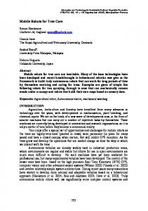
Audio Localisation for Mobile Robots
Figure 2 : Guiding of transportation of people and goods
Thibaut de Guillebon ‐ End of studies training Report ‐ August 2009
11 / 51
Audio Localisation for Mobile Robots
3.2.2. Project objectives The general objective of this project is the development of new ways of cooperation between network robots and human beings and/or the environment in urban areas, in order to achieve efficiently tasks that in the other way can be very complex, time consuming or too costly. For example, the cooperation between robots and video cameras can solve surveillance problems in urban areas, or the cooperation between robots and wireless communication devices can help people in several ways. The focus of the project is in urban pedestrian areas, an important topic in Europe where there exists a growing interest in reducing the number of cars in the streets and improving the quality of life. Network robots can be an important instrument to address these issues in the cities. Network robots is a new concept that integrates robots, sensors, communications and mobile devices in a cooperative way, which means not only a physical interconnection between these elements, but also, for example, the development of novel intelligent methods of cooperation for task oriented purposes, new communication languages between the different elements, or new mobility methods using the ubiquity of sensors and robots. We have identified several scientific and technological challenges, when thinking on network robots for urban areas, which have been taken into account to define the objectives of this project. The objectives of this project are the following: A scientific and technological objective: Develop an adaptable cognitive network robot architecture which integrates the following functionalities (sub‐objectives) ‐Cooperative localisation and navigation. ‐Cooperative environment perception. ‐Cooperative map building and updating. ‐Human robot interaction. ‐Multi‐task negotiation. Wireless communication with hand held devices, ubiquitous sensors, and other robots. An experiment objective: Test the cognitive network robot architecture in two different urban tasks: ‐Guiding and transportation of people and goods. ‐Surveillance. The first main objective of URUS is to develop an adaptable cognitive network robot architecture which integrates the basic functionalities required for the network robot system to do urban tasks. Cooperative localization and navigation: The specific objective is to extend the navigation capabilities of the robots by using cooperative localisation, perception, maps, short‐term‐planning robot navigation and cooperative control in unstructured and dynamic environments, in particular for urban settings.
Thibaut de Guillebon ‐ End of studies training Report ‐ August 2009
12 / 51
Audio Localisation for Mobile Robots Cooperative perception environment: The specific objective here is to create and maintain a consistent view of the urban world containing dynamic objects, i.e., pedestrians, vehicles (autonomous or conventional small transportation vehicles), by means of the information provided by the robots and sensors embedded in the urban environment. Cooperative surveillance tasks including the fleet of robots and the embedded sensors will be addressed, including cooperative event detection and identification. The cooperation not only includes the fusion of data, but also the development of adequate actions for developing these tasks. Also, decentralized cooperative tracking techniques for the estimation of the people flow and other moving objects in a certain area will be considered. Cooperative map building and updating: The specific objective is to augment the classical static Simultaneous Localization and Map Building (SLAM) problem to deal with dynamic environments, and to be cooperative using not only a troupe of robots, but all the different elements of the NRS, where the static (background) and moving elements (foreground) must both to be taken into account, at all times during map construction. For urban areas, one could take advantage of a GIS (Geographic Information System) for background information and rely on state of the art cooperative SLAM for dynamically updating such map, and for detecting the foreground. Human robot interaction: The specific objective is developing a series of tools to have a robust communication interface between robots and persons and a simple but friendly head for the urban robots. A person will communicate to a robot by means of mobile phones, voice and gestures. The robot will communicate to a person by voice, a robot screen or through the mobile phone. The mobile phones will be the main communication interface that will allow the human beings to ask for assistance, help or any other order, and moreover they will be used to have the first location approximation of the person in the urban site (this last task will be done in work package 7). That means that we will define a bidirectional language communication using mobile phones. The robot touch screen will be an interactive device to interchange information. The human gestures will be used for two actions: to express very simple commands and to locate a person in a specific urban point. An important issue will be to locate precisely a person by identifying its gestures. Finally, we will develop a simple but friendly head for the urban robots which will include the elements described in this work package. Multi‐task negotiation: The specific objective is to use general optimal or suboptimal techniques to achieve multi‐system task allocation among the members of the system, that is, the robots and the sensors and other systems of the environment. In this project, we will consider a set of heterogeneous robots with capabilities of interaction with the environment and with humans. The team of robots will be heterogeneous due to their motion capabilities (kinematic, dynamic), the type of sensors on‐board, their visibility and the communication constraints between robots and the environment. Wireless communication with hand held devices, ubiquitous sensors, and other robots: The specific objective is to extend the localisation of human beings fusing information from typical communication systems (mobile phones, embedded and mobile sensors) and detecting hand human movements; improve the communication recovery with robots and humans; and establish a common
Thibaut de Guillebon ‐ End of studies training Report ‐ August 2009
13 / 51
Audio Localisation for Mobile Robots wireless interactive language and protocol for the communication between humans (by means of mobile phone), robots and ubiquitous sensors. The second main objective is to test this cognitive network robot architecture with the specific goal of achieving the deployment of a network of robots, sensors and communication devices for the following urban oriented tasks that will become experiments in the URUS project quoted before: ‐Guidance and transportation of persons and goods. ‐Surveillance. The first experiment will consist in assisting people to find places to go and to transport people and goods from one place to another, using the best path taking into account for example, the map information and the on line street situation obtained by the network of robots. For the purpose of assisting people, some of the community of robots will have special interfaces to communicate with people (special monitor, new generation of mobile phones, PDAs etc.) and the people will use similar devices to communicate with the network robots. In this task, we need an accurate estimate of the position of the person that requires the service, and for this reason sensor integration for localization is of uttermost importance; for example, by tracking the person with vision sensors, by aiding in his/her localization from mobile phone signals, by identifying the person by his/her movements and by referring such data to a map (if such exists). With respect to transportation, some of the robots will be prepared to transport people and goods (small size). Figure 1 shows a virtual view of the Guiding and Transportation of people and goods task. The second experiment will consist in a surveillance task. Some robots in conjunction with the network will navigate the urban area to detect abnormal situations (vandalized urban furniture, big areas with trash, suspicious activity etc.). Moreover the network robots will be used to measure the flow of people in the streets or the flow of mobile elements in the area. For this purpose some of the community of robots will have special sensors and they will have to cooperate to exchange information, and give their location to send an alarm when they detect something strange. In the two tasks, there will be cooperation among robots, sensors and communication systems. Basically the six functionalities aforementioned must be taken into account, however with different priorities. The network of robots, sensors and communications will be tested in two different environments: a full experiment will be in the Campus of the Technical University of Catalonia, in Barcelona, which includes streets, passages, and closed environment (shops, restaurants, offices); and secondly a more limited testing will be performed in a selected “Superblock” (Supermanzana) of the city of Barcelona. At present there are several superblock studies in Barcelona, for example in Poble Nou, 22@, and Gracia’s quarter.
Thibaut de Guillebon ‐ End of studies training Report ‐ August 2009
14 / 51
Audio Localisation for Mobile Robots
Thibaut de Guillebon ‐ End of studies training Report ‐ August 2009
15 / 51
Audio Localisation for Mobile Robots
3.2.3 Participant List
*CO = Coordinator CR = Contractor ** Normally insert “month 1 (start of project)” and “month n (end of project)” These columns are needed for possible later contract revisions caused by joining/leaving participants
Thibaut de Guillebon ‐ End of studies training Report ‐ August 2009
16 / 51
Audio Localisation for Mobile Robots
4. DESCRIPTION OF THE INTERNSHIP
4.1. INTRODUCTION There are many techniques used by humans to estimate the location of a source of sound. Some of them can be reproduced on a mobile robot equipped with two microphones and modest processing power to apply the adequate algorithm. All the cues used by a human to localize the source of a sound and some of them are not yet fully understood. Some are easier than others to model and reproduce on a robot. The robots of the URUS project have to detect sound so they need a audio system for sound localisation that is the problem we have to solve in this subject.
4.2. SUBJECT The aim of the internship is to realise a simple system able to recognize the direction of the source. The localization must be performed by a rotating movement of the head, until it gives the good direction.
4.3. OBJECTIVE The robot should give in his final version the good direction of the audio source. This objective doesn’t consider the fact that reverberations in a small room make the detection really difficult to find. Our system will present a solution of the problem only in adequate conditions.
4.4. CONDITIONS OF THE WORK / CONSTRAINTS The first part of this work was to find different solutions, realizable with the main material proposed, the DSPIC30F4011. This study needed a research work to have different propositions in case one of the solutions was not sufficient. The system is based on a system of 2 or more electrets microphones. The signals have to be treated and amplified to be recovered by the DSPIC, which will be used to treat them and obtain an indication of the direction. A servomotor will be used to operate the rotating movement of the axis of microphones (whose the perpendicular will be considered as the direction similarly to human ears), in order to detect the good direction. This work has to be started from the beginning, with simple microphones, and a DSPIC. Therefore all should be prepared to let the audio signal treatment possible: the electronic system, the detection system, the rotating system and the algorithm in order to realise a continuous detection have to be realised for this.
Thibaut de Guillebon ‐ End of studies training Report ‐ August 2009
17 / 51
Audio Localisation for Mobile Robots This project requires equipment that is grouped in the work room, which is not the best in terms of the acoustic tests and all the verification of the detection system. The part of the evaluation of the robustness of the work has to be done outside this reverberant room.
4.5. CONTEXT This project is a part of a the European project, in which Spain, France, Switzerland, Italy, Portugal and the United Kingdom have to coordinate their work to insert a network of robots in order to improve the quality of life in such urban areas. The name of this project is URUS. This study is programmed in three years, and actually we are on the middle of the program.
4.6. ORGANIZATION This subject was put forward as a research subject, and was open to many different possibilities. Total liberty permitted to develop a part more than the other, and to conduct the research where it seemed to be the most required. The first part of the internship was based around research. Many solutions had to be found, to anticipate the fact that the first that would be tested would not be necessarily be the good correct one This subject has already been studied and yet some research effort has been devoted to microphone array processing techniques, especially for teleconferencing and large room recording, but also for speech recognition. For this reason, it was not so hard to collect the different possibility in researches done by the past in the last years. After having prepared these options, simulations have been realised to confirm the fact that the solutions should work properly, and permitted to develop a beginning of what the final algorithm should be. An electronic part had to be done, to obtain amplified and exploitable signals by the DSPIC30F4011. So a symmetric amplificatory system has been designed to permit this amplification. After that, the algorithm of detection made in the simulation with real audio signals with an Analogical/Digital conversion board which enabled the confirmation of the availability of the simulation of our solution, and to give an indication on the reliability of this simulation work. To continue, this project had been established on the DSPIC, with the best parameters possible that could keep a good reliability and a good resolution of the problem. To conclude, the servomotor has been integrated to the circuit, and now enables to rotation of the microphone axis in the good direction, with an algorithm based on the simulation done.
Thibaut de Guillebon ‐ End of studies training Report ‐ August 2009
18 / 51
Audio Localisation for Mobile Robots
5. AUDIO LOCALIZATION FOR ROBOT
5.1. INTRODUCTION This project will be explained in the order that it was that it took place: In first part, the two main ideas that were developed will be described. The theory will be established, and then we will then proceed to presenting the work concerning the simulation of these two solutions. After that, the electronic part to obtain the signals required and the implementation with the DSPIC of the processing will be presented. In a final part, the mobile part with the servomotor used and the final algorithm of the detection will be explained. These solutions do not consider the reverberation of the environment and this problem is not studied yet. The implementation of an algorithm aimed to develop passive acoustical source localization and tracking, is presented by employing as reference framework of the amplitude difference and time difference of arrival. In order to reduce the computational effort and facilitate the detection, an amplitude comparison and a cross‐correlation based approach are proposed for parameters calculation. This part of the project is based on the fact that the human ear uses these two methods to detect the sound. Indeed, the human ear uses more than these two simple methods, but these are the easiest to understand and to implement for a robot which has to detect a source. The sound I used to work is a sinusoidal signal (for me an A at 440 Hz), and my work was studied in two dimensions. Two electrets microphones were used to represent the two ears of the human as the ears of the robot.
Thibaut de Guillebon ‐ End of studies training Report ‐ August 2009
19 / 51
Audio Localisation for Mobile Robots
5.2. THEORICAL SOLUTIONS 5.2.1 First solution: Amplitude comparison The most important advantage of this solution is that it is really simple to understand and to implement. It is based on the fact that in a neutral and soundproof location, we can use the propriety of the sound that its amplitudes decrease as the distance with the source increase.
Figure 3 : Considerable angles around the head
The law of inverse square indicates that the amplitude of a spherical sound decreases by 6dB for each doubled distance will have a direct impact on the interaural amplitude difference. With the same azimuth there will be an amplitude difference more important for a source which is near the ear (or the microphone) than for a distant one. This should be one of the problems of this solution. It is difficult to give a real relation of this effect because it depends on many factors like the frequency and duration of the sound and others. The advantage of this system is that the human head makes this difference more important than it should in relation to distance, acting as a barrier between the two ears. The disadvantage is that a lot of factors change the amplitude response, and the reverberation changes al lot the values, so it is not an accurate solution, even if it will be used to help our system. Even if we test it in good conditions, the difference will not be the same with the distance, and it is normally the brain that interprets it for the human. Our detection system will use the fact that from an equidistance of the ears or the microphones, the amplitude of the signal is the same (so in the figure3, it corresponds to the azimuth 0° and 180°). The maximum of the difference in amplitude will be found for 90° and 270°.
Thibaut de Guillebon ‐ End of studies training Report ‐ August 2009
20 / 51
Audio Localisation for Mobile Robots Our electronic system must rectify the sinusoidal signals and compare both of them to determine the most important amplitude, and turn to obtain an equality of the signals. The electronic advantage of this solution is that it is really simple to realize with an analogical system. The disadvantage is that the signal should be higher in amplitude than the diode voltage that will rectify the sinusoid.
5.2.2 Second solution: Time differential of arrival This solution is based on the fact that the speed of sound in air is approximately 340m/s in normal conditions. With this knowledge, we can obtain a time difference between the two ears or the two microphones. The difference is null if the source comes from the azimuth 0° or 180°, and will be maximum for 90° and 270°angles. For a human being, the maximum time is approximately 0.65 ms, with a distance of 20cm between the two ears. These approximations are due to the fact that the distance between the ears is different for each person, and that the speed of sound depends on the temperature.
Figure 4 : Both microphone positions and a source in a simple acoustic field
We consider point A and point B as the ears or microphones. The distances from the source to these points are d1 and d2. The acoustic signals for these two points are: Where s(t) is the acoustic signal of the source measured in A, α is an amplitude coefficient and ηa and ηb are the independent noise components. If we consider that the distance between the source and the microphones is far enough, behind the distance between the two microphones, we get: We can obtain the time differential of arrival between the point A and B: Thibaut de Guillebon ‐ End of studies training Report ‐ August 2009
21 / 51
Audio Localisation for Mobile Robots
Figure 5 : Obtaining the time differential of arrival
We can deduce an approximation of the azimuth with the relation: Where c corresponds to the celerity of the sound, τ corresponds to the delay and dmic the distance between the microphones. The advantage of this method is that it is more efficient in a disrupted environment than the precedent than the one previously discussed and it can work with every kind of signal. It also gives directly an angle, but this angle will be more accurate if the azimuth is around 0°. The disadvantages are that it requires an important sample time to implement an algorithm able to find this angle. This solution does not prevent the reverberation problem that changes a little the real value. The implementation of this solution will be resolved with a cross‐correlation calculated by the DSPIC.
Thibaut de Guillebon ‐ End of studies training Report ‐ August 2009
22 / 51
Audio Localisation for Mobile Robots
5.3 SIMULATIONS 5.3.1. First simulation: Amplitude comparison Electronic simulation: First, a model of what could be the electronic work to obtain the two signals was realised with Simulink. This part contains for both of the signals: ‐ A first part that creates the signal for each microphone with the amplitude and a variable factor for the noise. ‐ An adjustable Lowpass Filter which cleans the audio signal by removing variations introduced by the noise. ‐ An adjustable amplification. ‐ A rectification (choice between half‐wave rectification and full‐wave rectification whose the basic ideas are described by the two figures 6 and 7).
Figure 6 : Half‐wave rectification
Figure 7: Full‐wave rectification
‐ Another Lowpass filter which keeps the continuous signal from the sinusoidal signal rectified. Finally this last Lowpass filter was replaced by a method of smoothing with capacitor, for better results reasons. Signals simulation: Utilisation of the “Audio Systems Array processing Toolbox “ After having simulated the electronic part which gives the continuous signals, the problem was to verify that this method would be efficient in real conditions. I have found a Toolbox developed by the
Thibaut de Guillebon ‐ End of studies training Report ‐ August 2009
23 / 51
Audio Localisation for Mobile Robots University of Kentucky in audio system laboratory by the Department of Electrical and Computer Engineering called «Audio Systems Array processing Toolbox». Description of the Toolbox: This toolbox (under development) is a collection of Matlab functions useful for simulating and processing data from audio array systems. In array systems signals are processed with respect to a spatial geometry of the microphones and sources. So in addition to typical time and frequency characterizations of audio sources and receivers, positions and spatial paths must be known and incorporated into the processing. The Matlab functions in this toolbox have a standard convention for vectors and matrices that provide position information. Functions developed around these conventions allow for efficient reuse, compatibility, and modification of toolbox functions. The following matrix and vector conventions apply to all applicable toolbox functions: Collections of signals associated with an array are stored columns‐wise in a matrix (row indices correspond to time sample and column indices correspond to signals from different microphones or sources). Larger row indices correspond to more recent time samples (row index 1 is the oldest sample). Positions of array elements, sources, and other elements in space are denoted with column vectors or column‐wise in matrices where each column corresponds to a position and the rows correspond to the x, y, and z coordinates of the position. If only 2 dimensions are given (2 rows) the algorithms will work in a plane (2D). If one dimension is given the algorithms will work along a line, which may be appropriate in applications such as calibration procedures for end‐fire arrays or speed of sound measurements. The field of view (FOV) defines the spatial limits for analysis or imaging. The FOV is limited to rectangular/cubic dimensions and is a 2 column matrix denoting the coordinates of opposite corner points. The coordinates of the array elements and FOV must be with respect to the same spatial frame of reference. The above conventions simplify the programming and use of toolbox functions with few limitations. Note there is no limitation on the number of array elements or the array element geometry. This Toolbox is a specific and complete toolbox for the audio systems, so some functions had to be simplified and adapted to remove the reverberation effects. Indeed, the room (asymmetric) where these experiments took place is too difficult to simulate, because the geometry and all furniture and equipment which are inside would be too complicated to establish, and the results would be erroneous for this reason.
Thibaut de Guillebon ‐ End of studies training Report ‐ August 2009
24 / 51
Audio Localisation for Mobile Robots This Toolbox was exactly what I needed to simulate the signals with more reliability. It was used to simulate an audio sinusoid source with two microphones placed in a room with adjustable characteristics. With this function, a simple interface was made to represent the room, and the three key elements:
Figure 8 : Matlab interface used to show locations of the elements
For instance, simple utilisation with a sinusoidal signal in this condition gives a response for the two microphones, like in the next graph shown:
Figure 9 : Simulation of the two audio waves for each microphone
Thibaut de Guillebon ‐ End of studies training Report ‐ August 2009
25 / 51
Audio Localisation for Mobile Robots Then, I made an interactive simulation between my electronic simulated part, the signals simulated by the Toolbox, and the interface to verify that the system was efficient. At the end of the simulation, the axis of the microphones has moved in the direction of the source position, even with noised signals. These are the representation of the two noised signals at the beginning of a simulation with 440Hz for the same location of the elements in the room:
Figure 10 : Simulation of the two audio waves at the beginning
At the end of the simulation:
Figure 11 : Positions of the microphones at the end
The precision is not totally reliable, because it is very difficult to consider all the factors in the simulation, but it gives an idea of what would be the adjustment for each parameter.
Thibaut de Guillebon ‐ End of studies training Report ‐ August 2009
26 / 51
Audio Localisation for Mobile Robots
Figure 12 : Simulation of the two audio waves at the end
5.3.2 Second simulation: Time differential time of arrival The same tools were used to simulate the second solution. The audio Toolbox and the same interface were used to simulate the signals and the elements in the room. The Toolbox was used to create a cross‐correlation system with a specific function. It was really simple to create a simulated implementation of this numeric solution, because a lot of functions like cross‐correlation or Fast Fourier Transfer have been studied by the University for Equivalent Projects: there was no need to create my own function for this reason. For this part, we consider that the two microphones are spaced by 25 cm. ‐Determination of an appropriate sample time: In theory, the maximum delay between the two signals, in a soundproof room in optimal conditions is 0.718 ms for the extreme angles. If we use a sample time of 10000 Hz, the accuracy of our measurement will be around the tenth of millisecond. Consequently, we will obtain 8 possible delay values and the good resolution for the angle would be around 10° (around because it is different for the small angles than for larger ones). Based on the same reasoning, with a sample time of 100 000Hz, We obtain accuracy around the hundredth of millisecond for the delay, and a reasonable resolution could be around 5° or less. This reasoning let us think that we have to set a sample time between this two frequencies: 10 000 Hz