etry and the underlying myocardium thickness. ... portion of viable myocardium is a major factor in determining whether ..... hibernating myocardium,â in Int. Conf.
AUTOMATIC MYOCARDIUM SEGMENTATION IN LATE-ENHANCEMENT MRI C. Ciofolo, M. Fradkin, B. Mory
G. Hautvast, M. Breeuwer
Medisys Research Lab, Philips Healthcare 51 rue Carnot, BP 301, 92156 Suresnes Cedex France
Philips Medical Systems Nederland B.V. Veenpluis 4, 5684 PC Best The Netherlands
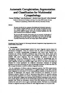
ABSTRACT We propose a novel automatic method to segment the myocardium on late-enhancement cardiac MR (LE CMR) images with a multi-step approach. First, in each slice of the LE CMR volume, a geometrical template is deformed so that its borders fit the myocardial contours. The second step consists in introducing a shape prior of the left ventricle. To do so, we use the cine MR sequence that is acquired along with the LE CMR volume. As the myocardial contours can be more easily automatically obtained on this data, they are used to build a 3D mesh representing the left ventricle geometry and the underlying myocardium thickness. This mesh is registered towards the contours obtained with the geometrical template, then locally adjusted to guarantee that scars are included inside the final segmentation. The quantitative evaluation on 27 volumes (272 slices) shows robust and accurate results. Index Terms— Image Segmentation, Late-Enhancement, Magnetic Resonance Imaging, Cardiovascular System, Automation. 1. INTRODUCTION Viability assessment is essential for surgery and therapy planning following a myocardial infarction. In particular, the proportion of viable myocardium is a major factor in determining whether a patient may benefit from revascularisation. In addition to estimating the left ventricular function with a cine Magnetic Resonance (MR) sequence, it is possible to visualise normal, ischemic and non-viable areas with high spatial resolution, using late-enhancement cardiac MR imaging (LE CMR). In a typical MR examination, a contrast agent is injected, the cine sequence is acquired approximately at the same time and finally, the LE CMR acquisition is done around twenty minutes later. During this time, the patient is supposed to have stayed still on the table. At the LE CMR acquisition time, due to the loss of membrane integrity in infarcted tissues, the constrast agent accumulates in abnormal parts of the myocardium, which are consequently enhanced (become bright) while healthy myocardium remains dark, as shown in the sample slice of Fig. 1.
978-1-4244-2003-2/08/$25.00 ©2008 IEEE
225
Fig. 1. Sample short-axis LE CMR slice
To locate and quantify non-viable tissue, the first step is the delineation of the endo- and epicardial contours on every slice (typically 10 to 20) of the LE CMR short-axis volume, which is tedious and time-consuming when done manually. However, automatically performing this task is challenging and, to our knowledge, not yet offered by any commercial product. Indeed, recent studies involving viability assessment generally use a manual or semi-automatic method to obtain the myocardial contours [1, 2]. Even the numerous publications that describe automatic methods for myocardium delineation, involving shape and appearance models [3, 4], deformable meshes [4], level sets [5, 6] or graph-cuts [7], are designed for cine images. The main difficulty with processing LE CMR volumes is the non-homogeneous intensity of the myocardium resulting from contrast agent accumulation in infarcted areas. However, the patient does not move between the cine and LE acquisitions, it is thus interesting to use a segmentation result obtained on the cine data as prior knowledge to automatically segment the myocardium in the LE volume, as proposed by Dikici et. al. [8]. The main challenge in this approach comes from the unintentional patient movements due to relaxation and breathing between the cine and LE acquisitions, which may induce an elastic displacement of the heart and surrounding organs, resulting in a correspondence loss between the slices in both volumes. For this reason, instead of using a 2D registration framework as in [8], we prefer a 3D approach combined with dedicated processing on the LE volume. This paper is organised as follows: the automatic myocardium segmentation method is presented in Sec. 2 and quantitatively assessed in Sec. 3, then we conclude in Sec. 4.
ISBI 2008
Ci (s) = C(s) − 0.5 w(s)n(s) Co (s) = C(s) + 0.5 w(s)n(s)
Fig. 3. Template geometry (left); Detailed zoom (centre). C(s) = (x(s), y(s)) and a variable width w(s), both of which are continuous spline interpolations of a discrete set of {pk = (xk , yk , wk )} samples defined at each node (see Fig. 3). This compact representation provides a natural coupling between the endocardium Ci and the epicardium Co (the inside and outside contours). We also define the two regions M and B, corresponding respectively to the myocardium and blood pool (see Fig. 3).
Fig. 2. Segmentation workflow 2. METHODS Our automatic segmentation method combines several techniques to find the myocardial contours. The workflow is described in Fig. 2. First a 2D geometrical template is used to find the myocardial contours position in each slice of the LE CMR volume (step A). Despite its robustness, this approach may lead to inaccuracies along the myocardium borders. This effect is thus compensated by the shape prior that is introduced with a 3D mesh built from the cine image sequence of the same patient. This mesh is registered to the LE CMR volume (step B) and deformed towards the 2D contours obtained at step A to achieve the final myocardium segmentation. 2.1. Step A: 2D segmentation with a geometrical template Template initialisation. The myocardium is robustly located with a variant of the Hough transform tailored to the detection of annular shapes. Its dark and circular appearance make it detectable as the best response to the convolution of the image with a radially-symmetric kernel modeling a dark ring. The radial profile of the kernel is defined as follows: � � (r−ρ)2 1 − 2σ2 √ e , fρ (r) = Δ σ 2π
Template deformation. We aim at finding the set of parameters minimizing a criterion that expresses the match of the template and the image evidence, given some prior knowledge. Built from observations of typical cardiac short-axis images, this knowledge is translated into mathematical terms expressing shape, contour and region constraints. In the remainder, I is the image and the λi ’s are � scalar weights Tbalancing the� various terms. Let p = pk = (xk , yk , wk ) , k ∈ �1, N � be our parametric model. The problem can now be formalised as follows: � � min F (p, I) = Fs (C, w) + Fc (Ci , Co , I) + Fr (M, B, I) p �
� �
� � � shape
contour
region
Shape: The centreline curvature and the width should both have small variations, which yields: 1 1 2 Fs (C, w) = λ0 |κ(s) − κ| ds + λ1 |w� (s)|2 ds, 0
0
where κ(s) is the centreline curvature, with average κ. Contour: The epicardium and the endocardium walls are preferred locations of image gradients, as expressed by: 1 1 ∇Iin (s)ds − λ3 |∇Ion (s)| ds, Fc (Ci , Co , I) = λ2
where ρ is the radius of the ring and Δ is the Laplacian operator. A ring of radius ρ is thus represented by the Laplacian of a Gaussian function shifted by ρ. Its width is directly related to the standard deviation σ, chosen according to the expected thickness of the myocardium. We compute the convolution in the Fourier domain for various ρ and choose the best response, which defines the optimal centre and radius of the deformable template initial position.
where ∇Iin = ∇I(Ci (s)).n(s) (resp. ∇Ion with Co ), ∇I is the image gradient and n(s) is the outward-pointing normal to the centreline. To implement this term, we use gradient filters that express prior knowledge on the relative intensity of normal and abnormal parts of the myocardium, as explained in the Special processing paragraph below.
Template description. The myocardium is modeled as a closed ribbon structure with an imaginary centreline
Region: The blood pool grey levels should be homogeneously distributed. Also, normal myocardium tissues are dark while
226
0
0
quadrant is higher than the blood pool average intensity: |I(x, y)|dxdy > ¯b Mi
(ii-Homogeneity around the expected value) The intensity dis¯ persion with respect to a ¯ is lower than with respect to h: ¯ |I(x, y) − a ¯|dxdy < |I(x, y) − h|dxdy
Fig. 4. Definition of quadrants
Mi
abnormal ones are bright, which results in a strong global contrast with the blood pool. Therefore we have: λ4 Fr (M, B, I) = |I(x, y) − m| dxdy |M| M
λ5
I(x, y) − b dxdy + λ6 (m − b) + |B| B where region B has an average intensity b and area |B|, while the expected intensity is m for the myocardium region M. Special processing for abnormal tissues. Even if abnormal tissues have different intensities than healthy regions, we cannot predict their location. To solve this problem, we propose to divide the myocardium in four anatomically meaningful quadrants whose locations depend on the position of the left and right ventricles (resp. LV and RV) centres (see Fig. 4). The LV centre is known from the template initialisation, whereas the RV centre is automatically detected with simple image processing operations such as correlation with the LV region . Then, instead of being computed on the whole myocardium, each term of the minimisation criterion is calculated separately in each quadrant, which has several advantages. First, the gradient filters defining the contrast terms are adapted to the quadrant location on the basis of anatomical knowledge. For example, in Q1 , we expect the myocardium to be darker than the surrounding RV whereas in Q3 , the contrast with the lung is low although a thin slice of bright fat is often visible. Second, computing the criterion terms separately allows the algorithm to detect abnormal tissue in a given quadrant and trigger an adapted processing. Abnormal tissue detection. To ease the detection, each slice of the LE CMR volume is pre-processed before the template deformation: the intensity distribution mixture is estimated with an Expectation-Maximisation algorithm, allowing to stretch the intensity range so as to saturate the darkest and brightest parts of the image. These areas respectively correspond to the healthy myocardium and abnormal tissues, which are consequently expected to appear as homo¯ and maximum (¯ geneous regions of the minimum (h) a) intensities in the new range. Then, in a given myocardium quadrant Mi = M ∩ Qi , i ∈ [1, 4], potential scars or ischemic areas are detected if all the three following conditions are met: (i-Brightness) The myocardium average intensity inside the
227
Mi
(iii-Homogeneity) The sum of the local gradient magnitude inside the myocardium quadrant is low. Inversion of criterion terms. If a scar is detected in Mi , the criterion terms are adapted. As the scar is brighter than the surrounding organs, the gradient filters defining the expected contrast along the borders are inverted. For the same reason, the expected value inside the myocardium m ¯ that is used in ¯ ¯ instead of h. Fr is a Optimisation. We use a greedy optimisation scheme embedded in a coarse-to-fine approach to optimise simultaneously the nodes position and ribbon width. This leads to robust and stable 2D segmentation results. However, inaccuracies remain along the borders (see the arrows in Fig. 5(a)). 2.2. Step B: 3D mesh alignment This step aims at introducing prior knowledge of the LV shape and thickness. This is done by using the short-axis cine MR acquisition that is usually acquired during the same examination as the LE CMR data and identifying the phase which matches best the late-enhancement acquisition time in the cardiac cycle. The myocardial contours can nowadays be easily automatically obtained for each cine phase [9]. They are thus extracted and gathered to build a 3D mesh representing the LV geometry and the underlying myocardium thickness. In order to register this mesh towards the LE CMR volume, we first compute the rigid transform between the cine and LE CMR data. This is done by estimating the LV axis on both volumes. Using the same detection algorithm as for the geometrical template initialisation (see Sec. 2.1), we obtain the LV centre on each slice. This gives a set of roughly aligned points, from which the axis is estimated by using a least mean squares algorithm with an outlier rejection step. The rigid transform which aligns the axes of the cine and LE CMR data is then calculated and applied to the mesh. 2.3. Combined A+B: deformation towards 2D contours If this axis-based registration aligns the mesh with the LE CMR data, it leaves some uncertainties concerning its position (resp. rotation) along (resp. around) its axis. This problem is difficult to solve by using the image grey levels only, that is why the mesh is deformed in 3D [10] towards the stack of 2D contours obtained at step A. This approach takes
to intra- and inter-observer variability. Moreover, when removing 4 bad-quality acquisitions from the dataset, the results are respectively 2.0 ± 0.4 mm and 1.9 ± 0.7 mm for the endo- and epicardium. As shown in Fig. 5, the visual quality is good, the contours successfully surround both normal and abnormal parts of the myocardium, which allows a reliable assessment of the percentage of non-viable tissue.
P1
P2
4. CONCLUSION We presented an automatic, robust and time-saving method for the fully automatic delineation of the myocardium contours in LE CMR images, which is an indispensable step in myocardial viability assessment.
P3
5. REFERENCES
(a)
(b)
(c)
Fig. 5. Contours for patients P1 to P3 . (a) Step A result and inacurracies (arrows), (b) Final result, (c) Manual contours. advantage of both the knowledge of the actual LV geometry (embedded in the mesh) and the myocardium borders position on the LE CMR volume brought by the contours. The deformation is done with an affine-to-local strategy: first we find the affine transform which gives the best fit between the mesh and the contours stack, without changing the mesh geometry; then we define a specific force F3D applied at each mesh vertex, taking into account the original shape of the mesh as a strong constraint (Fint ), the distance to the appropriate 2D contour (Fcont ) and the myocardium thickness (Fth ): F3D = Fint + Fcont + Fth . Finally, the mesh is locally refined by replacing the contour attracting force by a test on the image intensity (FI ) to guarantee that scars, i. e. bright areas, are included inside the final myocardial contours, leading to the following force: F3DRef ine = Fint + FI + Fth . 3. RESULTS We quantitatively assessed the performance of the method on a database of 27 LE CMR acquisitions (10 to 12 slices of 256 × 256 pixels) containing various types of abnormal tissues (large white transmural scars, sub-endocardial scars, scattered white areas...) by computing the distance between automatic results and manual delineations provided by experts (See Fig. 5(c)). The average error between the manual and automatic contours is 2.2 ± 0.6 mm for the endocardium and 2.0 ± 0.8 mm for the epicardium with a pixel size of 1.5 mm, which is close
228
[1] N. M. I. Noble et. al., “The automatic identification of hibernating myocardium,” in Int. Conf. Med. Im. Comp. Comp.-Assist. Interv. (MICCAI), 2004, pp. 890–898. [2] E. Heiberg et. al., “Semi-automatic quantification of myocardial infarction from delayed contrast enhanced magnetic resonance imaging,” Scand. Card. Jour., vol. 39, no. 5, pp. 267–275, 2005. [3] S. C. Mitchell et. al., “Multistage hybrid active appearance model matching: segmentation of left and right ventricles in cardiac MR images,” IEEE Trans. Med. Imag., vol. 20, no. 5, pp. 415–423, 2001. [4] M. R. Kaus et. al., “Automated segmentation of the left ventricle in cardiac MRI,” Medical Image Analysis, vol. 8, no. 3, pp. 245–254, 2004. [5] W. J. Niessen et. al., “Geodesic deformable models for medical image analysis,” IEEE Trans. Med. Imag., vol. 17, no. 4, pp. 634–641, 1998. [6] N. Paragios, “A variational approach for the segmentation of the left ventricle in cardiac image analysis,” Int. Jour. Comp. Vis., vol. 50, no. 3, pp. 345–362, 2002. [7] M.-P. Jolly, “Automatic segmentation of the left ventricle in cardiac MR and CT images,” Int. Jour. Comp. Vis., vol. 70, no. 2, pp. 151–163, 2006. [8] E. Dikici et. al., “Quantification of delayed enhancement MR images,” in Int. Conf. Med. Im. Comp. Comp.Assist. Interv. (MICCAI), 2004, pp. 250–257. [9] G. Hautvast et. al., “Automatic contour propagation in cine cardiac magnetic resonance images,” IEEE Trans. Med. Imag., vol. 25, no. 11, pp. 1472–1482, 2006. [10] O. Gerard et. al., “Efficient model-based quantification of LV function in 3D echocardiography,” IEEE Trans. Med. Imag., vol. 21, no. 9, pp. 1059–1068, 2002.