applying low-level electrical current to the paralyzed muscles so as to enhance .... transformer. Fig.4: Proposed circuit of LM675 based voltage current converter.
2013 IEEE 9th International Colloquium on Signal Processing and its Applications, 8 - 10 Mac. 2013, Kuala Lumpur, Malaysia
Current Source with Low Voltage Controlled for Surface Electrical Stimulation Aizan Masdar1, 3, B. S. K. K. Ibrahim1, 3, M. Mahadi Abdul Jamil2, 3, Dirman Hanafi1, 3, M. K. I. Ahmad1,3 and K. A. A. Rahman1,3 Department of Mechatronic and Robotic Engineering1, Department of Electronic Engineering2, Modeling and Simulation Research Laboratory3, Faculty of Electrical and Electronic Engineering, Universiti Tun Hussein Onn Malaysia, Parit Raja, Batu Pahat, 86400 Johor, Malaysia with a control algorithm either triggers preprogramed stimulation sequences or scales and reads the stimulation parameters out of a look-up table [4]. A transformer is also needed to step-up the voltage. The drawback is that this increases the device size and cost, and electromagnetic interference due to the transformer. The design of the transformer is also needed to handle the small mark-space ratio of the pulse. The wide range of amplitude is also restricted because of the fixed transformer turns-ratio [1]. Various control strategies and circuit design have been developed to provide enhanced functionality, repeatability, and a wide range of stimulation parameters for FES stimulator [5] in order to provide predictability of muscle responses. In general, complicated circuitry and control method are needed for this application which, in turn, imposes designs that are bulky, expensive, and high-power consumption [1]. This paper presents two viable solutions to the problem. The required components are small and the required input voltage is low. The circuits have three degrees of controllability which are amplitude, pulse width, and frequency and are ideal candidates for improvement of the FES circuit.
Abstract—Functional Electrical Stimulation (FES) is a promising way to restore mobility to Spinal Cord Injury (SCI) patients by applying low-level electrical current to the paralyzed muscles so as to enhance that person’s ability to function and live independently. However, due to the limited number of commercially available FES assisted exerciser systems and their rather high cost, the conventional devices are unaffordable for most peoples. Thus, this paper makes a comparative study of the various design of a multiple purpose portable functional electrical stimulator which is used in surface stimulation for patients with spinal cord injuries. The functionality, circuit performance and reliability of the circuits are presented. Keywords-Functional electrical stimulation (FES); voltage current converter; resonant circuit; low cost
I.
INTRODUCTION
In many years, FES has been applied to restore or maintain muscle activities of paralyzed patients who suffer from spinal cord injuries and related neural impairments [2]. FES is a promising way to restore mobility to SCI by sending electrical signals to restore the function of paralyzed muscles. In this technique, low-level electrical current is applied to an individual with disability so as to enhance that person’s ability to function and live independently [6]. It is important to understand that FES is not a cure for SCI, but it is an assistive device [3]. For SCI, the damage is only to the central nervous system, the muscle and its nerve supply remain healthy. By using FES, the paralyzed muscle is possible to contract due to the reaction of the artificial electrical stimuli. FES system mainly consists of electrodes and a stimulator unit. Current pulses will be generated from the stimulator unit through the electrodes and these cause the paralyzed muscles to make contraction. The main objective of FES in injuries to the central nervous system is the substitution of the absent bioelectric activity with an appropriately formed series of electric pulses, generated by a stimulator, or the elimination of the hyperactivity in paralysis and spastic paresis [8]. Several FES stimulators with microprocessor or microcontroller have been developed to improve lower and upper limb functions in subjects after SCI or stroke [7]. They generally operate with preprogramed stimulation patterns that are stored in a lookup table. Often, a single sensor combined
II.
In general, complicated circuitry and control method are needed for this application which, in turn, imposes designs that are bulky, expensive, and high-power consumption [1]. The required components are small and the required input voltage is low. The circuits have three degrees of controllability which are amplitude, pulse width, and frequency and are ideal candidates for improvement of the FES circuit. Conventionally, FES circuit is designed by using an oscillator which generates necessary pulse by using analogue electronics. The output waveforms including amplitude, frequency, and pulse width can be regulated. The output is then stepped up to the required voltage by a step-up transformer as shown in Fig.1. The drawback of using transformer is that this increases the device size and cost, and electromagnetic interference due to the transformer. The design of the transformer is also needed to handle the small mark-space ratio of the pulse. The wide range of amplitude is also restricted because of the fixed transformer turns-ratio. Various control strategies and circuit design have been developed to provide enhanced functionality, repeatability, and a wide range of stimulation parameters for
This work was supported by the Office for Research, Innovation, Commercialization and Consultancy Management (ORICC) and Centre For Graduate Studies of the Universiti Tun Hussein Onn Malaysia (UTHM).
978-1-4673-5609-1/13/$31.00 ©2013 IEEE
TRANSFORMER-BASED CIRCUIT
161
2013 IEEE 9th International Colloquium on Signal Processing and its Applications, 8 - 10 Mac. 2013, Kuala Lumpur, Malaysia
FES stimulator [5] in order to provide predictability of muscle responses. The transformer is used to further step up the output voltage. The function of this part is to transfer the output pulses of the multivibrator into a series of current pulses and a current feedback loop is included to ensure the current amplitude.
an external load of skin surface and will be called Rload through this paper. For the voltage-current converter circuit, R2, R3, R4, R5, R7, R11(Rload), U1A, U1B are absolutely essentials for obtaining the optimum performance of the converter circuit.
Fig.1: Typical circuit of a transformer-based FES [1].
III.
Fig.3: Proposed circuit of bipolar based voltage current converter.
From Fig.3, Va, Vb, Vc, Vd can be calculated as,
SWITCHING RESONANT-BASED CIRCUIT
Fig.2 shows the schematic diagram of the switching resonant circuit. The circuit is based on resonant converter [1] which has been used in power conversion but rarely used in medical electronics. It consists of two transistors and a set of resonant components and amplitude regulating components.
Va = ( R 7 + Rload ) ⋅ Io
(1)
Vb = Rload ⋅ Io
(2)
Vc =
R3 R2 ⋅ V1 + ⋅ Vb R 2 + R3 R 2 + R3
Vd = Vc =
R4 ⋅ Va R 4 + R5
(3)
(4)
From (3) and (4),
R3 ⎧ R4 ⎫ ⋅ V1 = ⎨ ⋅ R7 − M ⋅ Rload⎬ ⋅ Io (5) R2 + R3 ⎩ R4 + R5 ⎭
Fig.2: Switching resonant circuit FES [1].
IV.
PROPOSED CIRCUIT
While Rload coefficient, M
In this paper, bipolar based voltage-current converter circuit has been proposed as an output stage of FES and the functionality, circuit performance and reliability of the circuits will be examined through a simulation study.
=
R2 R4 (6) − R 2 + R 3 R 4 + R5
From (5), it can be said that the Io is not relying on the Rload when M is equal to zero. So that,
A. Circuit description Fig.3 shows the proposed circuit which consist of three kind of circuits. The voltage-current converter , voltage limiter circuit and current booster circuit which (R1, R2, R3, R4, R5, R7, R8, R11, U1A, U1B), (D1, U2A, R9, R10) and (R6, Q1) as the components respectively. R11 is assumed as
R2 R4 − =0 R 2 + R3 R 4 + R5 From (6), when
162
(7)
R2 R4 , Io is Rload independent. In other = R3 R5
2013 IEEE 9th International Colloquium on Signal Processing and its Applications, 8 - 10 Mac. 2013, Kuala Lumpur, Malaysia
words, the amplitude of the current Io is not affected by changes in the tissue load. The circuit shown in Fig.3 has a limitation which can only produces monophasic pulses. It also needed high voltage power in dealing with high voltage that occurs between the Rload in order to produce constant current continuously. Hence, the circuit has a necessity to be modified as shown in Fig.4. Then, both monophasic and biphasic current pulses can easily be produced by controlling the V3 as the voltage control. A power operational amplifier (LM675) is used which has a capability to produce current output with 3A as the maximum value. As shown in Fig.4, V1 and V2 are the power voltage of the circuit which produce polarity voltage. The V3 is the voltage control of the circuit in producing rated current as an output. V3 is actually can be controlled by microcontroller through Digital Analog Converter (DAC). Compared to the conventional transformer-based analog circuit, these circuits shown in Fig.3 and 4 are consist of only basic electronic components which are low development cost and have no bulky and expensive component such as a transformer.
stimulus can be produced from 10mA to 120mA in range with a step of 2mA and the pulse width of the stimulus can be produced from 10us to 500us in range with a step of 10us.
Fig.5: Simulation result of the proposed circuit.
Fig.6: Simulation result of the proposed circuit.
Fig.4: Proposed circuit of LM675 based voltage current converter.
B. Circuit performance The simulation for this proposed circuit has been done and the result is shown in Fig.5 and 6. The simulation has been done by gradually increase the V1 from 0V~5V in increments of 1V and V1 as a pulse voltage source . Since the voltage across the Rload is not over than the voltage set at the voltage limiter circuit, the output current increase with the maximum value of 500mA. However, current amplitude typically ranges from 10-150 mA in surface stimulation, depending on the application [9]. The output current Io as the vertical-axis correlate with the control voltage V1 with the relation of
Io =
1 Vin . Fig.7 shows the experimental result of the 10
circuit shown in Fig.4. In this experiment, 1kΩ of Rload has been selected and it is assumed as an external load of skin surface. It is calculated that the circuit possible to produce output current Io in relation of ± Io = ±V 3 with voltage control V3. Fig.7 and 8 show that the amplitude of the current
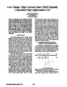
Fig.7: Biphasic current pulses with various current amplitude output for the circuit shown in Fig.4.
163
2013 IEEE 9th International Colloquium on Signal Processing and its Applications, 8 - 10 Mac. 2013, Kuala Lumpur, Malaysia
Instrumentation and Measurement, vol. 51, no. 1, pp. 2-9, February 2002. [3] Jacques, B. (1998). Can muscle models improve FESassisted walking after spinal cord injury? Journal of Electromyography and Kinesiology, 8(2):125-132. [4] J. J. Abbas, "Feedback control of coronal plane hip angle in paraplegic subjects using functional neuromuscular stimulation", IEEE Trans. Biomed. Eng., vol. 38, pp.687 -698 1991. [5] J. O. Teeter, C. Kantor, and D. Brown, Functional Electrical Stimulation (FES) Resource Guide for Persons With Spinal Cord Injury or Multiple Sclerosis, 1995 :Cleveland FES Center.
Fig.8: Biphasic current pulses with various current pulse width output for the circuit shown in Fig.4.
V.
[6] Kralj, A. and Bajd, T. (1989). Functional Electrical Stimulation: Standing and Walking after Spinal Cord Injury, CRC Press, Baca Raton, FL,USA.
CONCLUSION
The performance of transformer-based circuit and switching resonant based circuit is very similar and both can provide the required pulse pattern for use as an FES [1]. Transformer-based circuit is an analogue electronic circuit, which requires a transformer to step up the voltage. The transformer is also the most bulky and expensive component in the circuit. The component count is also high, therefore, in practice; surface-mount devices are needed. switching resonant based circuit is based on a zero-voltage switching resonant techniques. The main feature of the circuit is that no transformer is needed. Therefore, it obviously has the advantage of no large magnetic components. The resonant circuit proposed has a preferred feature and require less component and need no installation of a transformer. By contrast, this circuit is producing a voltage stimulus mode which effective control is needed as it affected to the changes of tissue-load. And there is also a drawback in controlling the switching timing using this type of circuit. Compared to the conventional transformer-based analog circuit, this circuit consists of only basic electronic components which has low development cost and has no bulky and expensive transformer. Besides, the current mode output stimulus amplitude is controlled by low voltage signal which is independent with the skin surface inductance or the changes of tissue-load.
[7] M. H. Grant, J. F. Keating, A. C. B. Smith, M. Delargy, and B. J. Andrews, "The use of functional electrical stimulation to assist gait in patients with incomplete spinal cord injury", Disability Rehab., vol. 14, pp.93 97 1992. [8] Pasniczek, R. and Kiwerski, J. (2004). Supporting of the Lost Function of the Human Extremities by Function Electrical Stimulation of Orthosis, Journal Medical Physical Engineering:43-5. [9] T. A. Thrasher and M. R. Popovic, "Neuroprostheses for restoring swallowing function", Perspectives on Swallowing and Swallowing Disorders (Dysphagia), vol. 13, no. 2, pp. 28-31, 2004.
REFERENCES [1] Cheng, K. W. E.; Lu, Y.; Tong, K. Y.; Rad, A. B.; Chow, D. H. K.;Sutanto, D. (2004) “Development of a circuit for functional electrical stimulation” IEEE Transactions on Neural Systems and Rehabilitation Engineering, v.12, n.1, p.43-47. [2] Han-Chang Wu, Shuenn-Tsong Young, and Te-Son Kuo, "A versatile multichannel direct-synthesized electrical stimulator for fes applications," IEEE Transactions on
164