a portmanteau word formed from domus (Latin, meaning house) and roboticsâ [4]. Today a lot of activities at homes and offices can be automated and controlled ...
International Journal of Computer Applications (0975 – 8887) Volume 97– No.9, July 2014
Design and Implementation of a Home Automatedn System based on Arduino, Zigbee and Android Application Abdulrahman Yusuf
Murtala Aminu Baba
Faculty of Science, Department of Computer Science, Yobe State University, Damaturu, Nigeria
School of Engineering and Engineering Technology, Abubakar Tabawa Balewa University, P.M.B.0248, Bauchi, Nigeria
ABSTRACT Due to the proliferation of modern technology, these days, the world is increasingly experienced the use of wireless devices. The devices such as remote control and GSM phone could provide means for monitoring and controlling home appliances in a more convenient way. This project has explored the concept of home automation and ZigBee technology. A home automated system based on Arduino and ZigBee are developed which is tried to be integrated with Android application through Home Gateway for network interoperability. To show the effectiveness and feasibility of this proposed system, a remote control, indoor control and outdoor control systems have been developed and evaluated. However, integrating the system with android application remains unsuccessful.
General Terms Mobile and distributed computing.
Keywords Zigbee; Arduino; Home appliances; gateway and remote control.
ZigBee performs two ways communication and do away with line-of-sight restrictions (pointing at the device). For this project work, using Arduino and ZigBee an automation device system of a particular house will be developed to control inner and outer home electrical appliances as well as integrating android phone application. For the inner home system four rooms lights will be controlled within the home. Servo gate will be automatically open upon shadow detection and also light will be automatically switch “ON” and “OFF” when sun sets and rises respectively by the outdoor system.
1.1
Statement of Problem
Today telecommunication is massively used in customer electronic sector. And it is very useful to have very handy device for controlling as well as facilitating activities around home. Therefore wireless remote control can be achieved using Arduino and ZigBee as well as GSM phone to control the interior and exterior home appliances. This is exactly what the proposed system should do.
1.2 Assumptions 1. INTRODUCTION The concept of home automation is being in place since 1980’s with the term dometics “Domotics is the application of computer and robot technologies to domestic appliances. It is a portmanteau word formed from domus (Latin, meaning house) and robotics” [4]. Today a lot of activities at homes and offices can be automated and controlled (example light, TV, door/gate and other home appliances) over a handy device (remote control or remote access) either inside or outside home or office. According to [11] a remote control is a device that is mostly small wireless handheld object for managing several settings by means of buttons arrays. In engineering remote control is the control of system or activity by a person at different place usually by means of radio or ultrasonic signal or by electric signal transmitted by Wire[4]. Due to the widespread of personal computing of consumer electronic devices such as media players, mobile phone and a like; peoples are increasingly accepting technology in everyday life which gives them more sophisticated avenue of home management for the aspects like security, comfort, energy efficiency, home media and other related issues [8]. ZigBees appear to be one of the technologies that allows global standard for advanced better, cost effective and ease of use remote control development [12]. They further explain
The proposed system to develop is expected to perform the following: Remote control (device 1) should instruct device 3 (interior controller) to light on/off of either room one, room two, room three or room four of a particular house. But room 4 switch would be a dimmer light. The interior controller is expected to respond by informing the device 1 which light of the room is on or off The light of room four can be regulated by dimmer switch from the remote control The exterior controller should inform the remote control once the outside light is automatically on or off during night or day respectively. The exterior controller should also inform the remote control when the servo gate is automatically open upon shadow detection and close if no shadow detected. Additionally, it may be possible by the users to remotely monitor and control the ZigBee based home devices using internet through the android phone. Where a gateway may be implemented to facilitate the internet connectivity.
37
International Journal of Computer Applications (0975 – 8887) Volume 97– No.9, July 2014
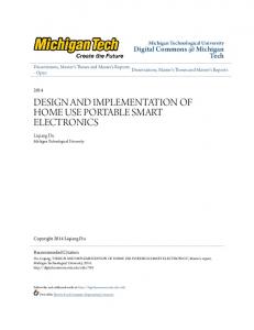
The design procedures and working principles of the whole system is organized into different units which include: control units (remote control, outer door control, and inner door control); home gateways (interfacing unit) and GSM android application. It also requires compiler to build programs which is used in Arduino microchip and ZigBee. Fig. 1 shows the conceptual architecture of the proposed system and some part of the image is from [6]
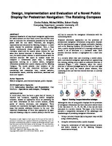
communicate at the rate of 250Kbps within the physical distance of about 50 miles [9]. The three switches are plugged on the board then to the Arduino to control the three inner rooms by switching on/off through pin 13, 12, and 11, a potentiometer as dimmer switch for dimming the 4 th room light through pin A1. The LCD screen which is 16x2 alphanumeric displays with 16 pins connected to the Arduino through board on pin 9, 8, 7, 6, 5 and 4 as well as 5V and GND to display messages from other units. Fig 2 gives the remote control circuit.
2.1
2.1.2 Inner Control Unit
2. SYSTEM DESIGN
Hardware Design
2.1.1 Remote Control Unit This central module is built using Arduino and ZigBee plus bread board with switches, a potentiometer and LCD screen. Arduino Uno is an integrated circuit consists of microcontroller, an ATMega328 RISK devices 30kb available flash memory and 32-8 bit registers and assorted programmable I/O lines [3]. The ZigBee is interfaced with Arduino for wireless personal area network (WPAN) operating at 868MHz, 902-928MHz and 2.4GHz and it can
The general function of this unit is to receive command from the remote control to light on/off of either room one, room two or room three or dimming room four as well as informing the remote control unit which room is on or altered. It consists of Arduino and ZigBee as explained under remote control unit. It has a bread board connecting the four positive legs of the LEDs to pins 13, 12, 8 and 11 respectively for digital read and each of the negative legs are connected to the ground through 560Ω resistor. The circuit diagram is depicted in the Fig. 3.
ZigBee Home Automation Network
Room1
Outdoor Room2 Room3 Room4
Device 3 controls 4 rooms
Remote control with control buttons and LCD screen
Device 1 controls auto light and gate
Servo Gate
Android phone
Fig. 1: Proposed System Conceptual Architecture
38
International Journal of Computer Applications (0975 – 8887) Volume 97– No.9, July 2014
LCD Potentiometer
Ground
LCD 1 2 3 4 5 6 7 8 9 10 11 12 13 14 15 16
Pin A1
Room 4 dimmer Switch
10KΩ
Pin 13
Pin 12
Pin 11 10KΩ
10KΩ
10KΩ
5V pin 9
pin 8 pin 7 pin6 pin 5 pin 4
Fig 2: Remote Control Circuit
Pin 13
Pin 12
Pin 8
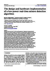
reading luminous intensity of less than 21 Lux (i.e when shadow detected) that allowed the current to pass through 100Ω and pin A1 active to the ground.
Pin 11
5V
Pin 13 LED1
LED2
LED3 LED4 Pin 9
560Ω A1
560Ω A1
560Ω A1
560Ω A1 Pin A0
LED 1.8KΩ
100Ω
Pin A1 100Ω
Servo
GND
Fig 3: Inner Control Unit GND
2.1.3 Outdoor Control Unit The general function of the unit is to send to the remote control whenever the gate is open and whenever the outside light is on/off upon sun sets or rises respectively. This unit is built using Arduino, ZigBee and a bread board contains a LED, Servo and two photo-resistors. What Arduino and ZigBee do are explained under remote control (section 2.1.1) above. The two photo-resistors on the board, one is connected to the LED and the other is connected for the servo. The light is automatically switched on when sun sets and off when sun rises. The gate is opened upon detection of shadow and closed when no shadow. The circuit is shown in the Fig. 4. The LED connected to pin 13 and to the GND through 1.8KΩ which switches on upon reading luminous intensity of less than 12 Lux (i.e when sun sets) which allow the current to pass through 100Ω and pin A0 active to the ground. The Servo is connected to the pin 9, GND and 5V which opens 1800 upon
Fig 4: Outer Control Unit Photo-resistors are used for this light sensitivity devices (i.e servo gate and outdoor light). This is because, in Photoresistor, resistance goes lower at the higher light levels but goes higher at the low light levels [2]. This sensor technology has limited frequency, bandwidth and linearity and its spectral response is within 350 and 1100nm but has ease of use, low cost and TTL signal level [7].
2.2
Home Gateway (Interfacing Unit)
Remote control access and interoperability to the home automation system through internet requires home gateways. Home gateway stands for ingress point in-between the personnel area network and internet (Public Access Network).
39
International Journal of Computer Applications (0975 – 8887) Volume 97– No.9, July 2014 The home web server based home gateway to interconnect home automation system with internet need to be developed [7]. This can be based on key technologies HyperText Markup Language (HTML), Web-based User Interface Web Server, HyperText Transfer Protocol, Common Gateway Interface (CGI) and Web Application Scripting or Programming Language [10]. The home gateway can play two primary functions. Firstly data translation services between the internet and ZigBee. Secondly provision of standardized user interface for the devices connecting to the ZigBee remote control [7].
Start
Initialisation
3. FLOW CHARTS Fig 5a shows flow-chart of remote control. Fig 5b shows flow chart of inner control unit of four rooms and Fig 5c shows flow chart of the outer control unit. It is clearly depicting from Fig 5a if a switch of a particular room is pressed a control signal is transferred to the Fig 5b which decodes and switches on/off the appropriate room light and sends back the action performed to the remote control which also decodes and updates LCD as well as sending SMS to the android phone. Fig 5c indicating the gate open upon shadow detection and outside light automatically ‘ON’ upon dark sensing and ‘OFF’ if not. The unit sends to the Fig. 5a upon any action happens which decodes and update the LCD and sends SMS to the android phone
Enable interrupts
Yes Is interrupt received?
No
4. SOFTWARE DESIGN AND IMPLEMENTATION 4.1 Arduino with ZigBee The software is designed with the use of Arduino Integrated Development Kid Environment that allows writing, compiling and uploading code to the board. The program or sketch is written using C programming language or C compiler. Three programs are written for three different systems: First the program for the remote control which allows the remote control to instruct inner control system to switch “ON” or “OFF” of either of the three rooms by switch press as well as dimming the light of room four through turning the potentiometer. The remote control program also allows for receiving signal from inner or outer control system of any action performs which is decoded and updated on the LCD screen. The complete program of the remote control unit is available with the developer. Second is the inner control program which performs switch “ON” or “OFF” actions as result of the instruction receives from remote control program unit and send back signal for any particular action done to the remote control. The actual work contains the code for inner control system. In the third outer system the program is written to allow automatic light switch on or off whenever sun is set or raise. It also inform remote control when the light is on or the servo gate is open. The code for outer control system is available in the actual work.
Is room 1 switch pressed
Yes
Send control signal to inner system
Yes
Send control signal to inner system
Yes
Send control signal to inner system
Yes
Send control signal to inner system
Wait No
Is room 2 switch pressed No
Is room 3 switch pressed No Is room 4 switch altered
Update LCD and send SMS to Phone Decode interrupt Stop Fig. 5a: Remote Control Unit Flow-Chart
40
International Journal of Computer Applications (0975 – 8887) Volume 97– No.9, July 2014
Start
Start
initializations
Initialisations
Enable interrupt
Wait
Is shadow detected?
No
Wait
Is any key pressed and interrupt received? Wait
Yes
No
Yes
Decodes
No Is night dark detected?
Yes
Open door or put light on
On/Off appropriate room Send status to remote control and SMS to phone for the action
Reply to remote control and send SMS to phone
Fig. 5c: Outer Control Unit Flow-Chart
4.2 Android Application
Fig. 5b: Inner Control Unit Flow-Chart
This software is tried to develop with the use of Eclipse Integrated Development Kid Environment, Java Development Kid, Android SDK, and android development tools (ADT) Plugin. Time and resources limitations and allows very little to be covered a particular application interface design shown in Fig. 6 and the code is available in the actual work.
41
International Journal of Computer Applications (0975 – 8887) Volume 97– No.9, July 2014 [2] Department. of Mechanical and Aerospace Engineering, 2011. Photoresistor Laboratory: Photoresistor, Transistor, and LED’s, USA: San José State University. [Accessed 18th April, 2013]. Available at: < www.engr.sjsu.edu/bjfurman/.../photoresistor-Arduino.d > [3] Dennett, C. 2013. 7CC003 DAMC Arduino Duemilanove WorkBookWeb [Online]. [Accessed 20th March, 2013]. Available at: [4] Delgado A. R., Picking R. and Grout V. 2005 “RemoteControlled Home Automation Systems with Different Network Technologies” Centre for Applied Internet Research (CAIR), University of Wales, NEWI, Wrexham, UK [Online]. [Accessed 15 March, 2013]. Available at: Fig 6: Android Apps Interface
5. EVALUATION The implemented system has been evaluated. To show the feasibility and effectiveness of the proposed system; four devices were developed but the forth one is partially developed: first is a remote control with four switches and LCD; second is an inner control system connected to the lights of four rooms; third is an outside control system connected to servo gate and outside light and the fourth is an android application integrated to act as GSM remote control for the home automation system. The system was subjected to the thorough testing in which some amount of delays have been observed especially between switch off press and its response. However, the system does as expected. Due to the time limitations as well as unavailability of appropriate materials for developing and integrating android phone to control the developed Zigbee home automation system. All the efforts for achieving that remained unsuccessful.
6. CONCLUSION These days, there were increasing used of wireless devices. The devices such as remote control and GSM phone provide means for monitoring and controlling home appliances (for example doors, lights and the rest). Integrating mobile phone to control and monitor home devices provide a more convenient way to alert users of the possible intrusion as well as avoiding user to be moving with additional equipment as almost every person use mobile phone. The home automation developed for this project remote control device, inner control device and outer control device communicated with some delay issues. But integrating it with android application has turned unsuccessful. Therefore, this remains the great limitation for further work.
7. REFERENCES [1] Balasubramanian, K. and Cellatoglu, A. 2009. Analysis of remote control techniques employed in home automation and security systems [online]. New York: Institute of Electrical and Electronics Engineers, Inc, pp.1401-1407. . [Accessed 18th March, 2013]. Available at: .
IJCATM : www.ijcaonline.org
[5] FALEX, 2013. The Free Dictionary [online]. [Accessed 15th March, 2013]. Available at: [6] Gill,K., Yang S., Yao F and Lu X. (2009) A zigbeebased home automation system [online]. New York: Institute of Electrical and Electronics Engineers, Inc, pp.422-430 [online]. [Accessed 15 March, 2013]. Available at: . [7] Godfrey L. 2012. Choosing the Detector for your Unique Light Sensing Application [online]. [Accessed 15 April, 2013]. http://www.johnloomis.org/ece445/topics/egginc/tp4.htm l [8] Khan, S. R. , Al-Mansur, A., Kabir, A., Jaman, S. and Chowdhury, N. 2012. Design and Implementation of Low Cost Home Security System using GSM Network. International Journal of Scientific & Engineering Research 3(3), ISSN 2229-5518 [online].[Accessed 15th March, 2013]. Available At: [9] Rouse, M. 2012. ZigBee Definition [Online]. [Accessed 18th March, 2013]. Available at: [10] Ting, J.(2013) 7CC003 DAMC Web Interfacing to Embedded Devices [Online]. [Accessed 20th March, 2013]. Available at: [11] Wikipedia 2013. ZigBee [Online]. [Accessed 20th April, 2013]. Available at: [12] ZigBee Alliance, 2013. ZigBee Remote Control Overview [Online]. [Accessed 11the March, 2013]. Available At:
42