After the discharge of capacitor bank 1, a high pulsed current would flow in the blank holder coils, that is, upper and lower coils. Then a high pulsed attractive ...
1
> 2PoCL-10
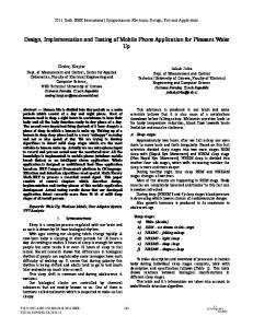
2PoCL-10< two coil systems are denoted by forming co il and blank holder coil systems, respectively. After the discharge of capacitor bank 1, a h igh pulsed current would flo w in the blan k holder coils, that is, upper and lower coils. Then a high pulsed attractive electro magnetic force can be generated between the upper and lower coils. The pulsed attractive force then would be transmitted to the flange region of the metal sheet as blank holding pressure through the blank holder. The magnitude of the BHF is determined by the discharge energy of the capacitor bank 1, while the temporal evolutions of the BHF can be controlled by the circuit parameters, such as capacitance, inductance and crowbar resistor. The relative operation timings between the BHF and the forming force also can be controlled by altering the trigger t imings of the discharges of blank holder coils and the forming coil. Herein, the discharge of forming coil would be started when the BHF nearly reaches its peak value. capacitor bank 1 CP
LP protection inductor upper coil attractive force
RL line resistor
Rd capacitor bank 2 forming coil
holding pressure
metal sheet
blank holder
lower coil
mechanical strength and thermal capacity to sustain the high mechanical and thermal loads during the discharge process. C. The design of coil system Based on the aforesaid requirements and constraint conditions, a design flow was discussed in this section. The first issue should be addressed is how to weaken the magnetic fields inside the bore of the coils and in the surrounding space of the coils, since this issue determines which structure the coils should be adopted. It can be verified that the conventional structure of the coils shown in Fig. 2 (a) can’t fulfill the requirement, since it can be seen from the magnetic flu x density distribution that the magnetic field inside the inner bores of the coils still has considerable magnitude, which would significantly influence the forming force generated by the forming coil on the metal sheet. To accelerate the decay of the magnetic field with respect to the distance fro m the blank holder co ils, as shown in Fig. 2 (b) we replace coil 1 in Fig. 2 (a) by sub-coils 1-a, 1-b (called upper coil), and replace coil 2 by sub-coils 2-a, 2-b (called lo wer co il). The currents flowing in sub-coils 1-a, 1-b (and in also sub-coils 2-a, 2-b) are with opposite direction. By this way, the magnetic fields, generated by the sub-coils 1-a, 2-a, and the sub-coils 1-b, 2-b, are with opposite directions inside the inner bore of the coils and outside the outer diameter of the coils, thus are effectively counteracted with each other. As a consequence, the magnetic field can be more rapidly decayed with respect to the distance from the blank holder coils.
die
Fig. 1 The schematic diagram of pulsed electromagnetic blank holder for electromagnetic forming.
B. Requirements on the coil system Two requirements exist for the pulsed BHF. (1) Firstly, the magnitude of BHF should be high enough so as to supply sufficient holding force on the flange region of the metal sheet. In this paper a BHF up to 800 kN is expected. (2) Secondly, the pulsed BHF should be with long enough pulse width so that in the whole process of the electro magnetic forming sufficient BHF is applied. Due to the fact that the duration of electromagnetic forming process is generally less than several hundred microsecond, thus a BHF with rise time (or called peak value time) larger than 4 ms is expected to be adequate to ensure a sustaining holding force during the whole forming process. Besides that, several constraint conditions exist for the design of the coil system. (1) Firstly, the magnetic field generated by the blank holder coils inside the inner bores should be with low intensity so as not to influence the generated pulsed Lorentz force, that is, the forming force on the metal sheet. (2) Secondly, the magnetic field in the surrounding space of the coils should be decayed rapidly enough with respect to the distance from the coils so as to lower the unexpected electro magnetic interference to the nearby electrical equipment. (3) Th irdly, the coil system should also be with enough
inflow of current outflow of current
(a)
coil 1
z
r
coil 2
magnetic flux gr
(b)
coil 1-b coil 1-a
z r din gz
w1
w2
Mid-plane
h
coil 2-b
coil 2-a
Fig. 2 T wo structures of coil system for pulsed electromagnetic blank holder. T ABLE I GEOMETRIC P ARAMETERS OF THE COILS. Symbol
Description
Value
d in w1 w2 h gr gz
Inner diameter of coil Width of sub-coils 1-a, 1-b Width of sub-coils 2-a, 2-b Height of sub-coils Radial gap between sub-coils Axial gap between sub-coils
250 mm 51.2 mm 51.2 mm 16 mm 3.75 mm 57 mm
After determine the structure of the coils, the geometric parameters of the coil system can be then determined by the geometric dimensions of the metal sheet and the die. These parameters are given in Table I. A fter that, we could determine
3
> 2PoCL-10< the parameters o f the capacitor bank, which should be capable of supplying enough energy to ensure the magnitude of the generated pulsed electro magnetic attractive force. By fin ite element calculation the linear relationship between the attractive electromagnetic force and the magnetic energy can be obtained. The result shows when the magnetic energy stored by the coil system reaches 290 kJ an 800 kN attractive electro magnetic force can be obtained. Considering the fact that a large amount of d ischarge energy would be dissipated as Joule heating before the discharge current reaches its peak value, we employed a capacitor bank (capacitance 3.2 mF, maximu m d ischarge voltage 25 kV) with maximu m stored energy of 1 MJ as the pulsed power source of the system. Furthermore, to limit the short-circuit current a protection inductor with inductance about 0.8 mH is series connected with the blank holder co ils. To fulfill the requirements on the rise time or pulse width of the BHF, we should ensure the rise time of the discharge current to be longer than 4 ms. Along with the geo metric parameters of the coils given in Table I, the requirement on the rise time may determine the turn of the coils. Herein, each sub-coil has 32 turns.
boards with thickness of 25 mm. The joint between the epoxy boards was realized by 72 screws and 72 nuts. The gaps between the windings and the epo xy board were irrigated with STYCAST 2850 FT. The die was made fro m steel. The lo wer coil, consisting of sub-coils 2-a, 2-b, was fixed on the die through 72 screws. In the discharge circuit, an inductor with inductance about 0.8 mH was series connected with the coils to limit short-circuit current, thus to protect the circuit system.
blank holder
upper coil
lower coil connection wire
D. A protype of pulsed electromagnetic blank holder system Copper (coil)
STYCAST2850 FT
Zylon
Epoxy board
T ABLE II CIRCUIT P ARAMETERS OF THE SYSTEM.
Axial coordinate (cm)
1 turn 32 layers
30
Pickup coil
Symbol
Description
Value
Cp RL LP Rd
Capacitance of capacitor bank Line resistance Protection inductance Crowbar resistance
3.2 mF 0.02 Ω 0.8 mH 0.2 Ω
25 20 20
T ABLE III MATERIAL P ROP ERTIES. 0
15 15
Material
Parameters
Value
Cooper
Density Heat capacity T hermal conductivity Relative permeability Reference resistivity (293.15 K) Reference temperature coefficient Electrical conductivity Density Heat capacity T hermal conductivity Relative permeability Electrical conductivity Density Heat capacity T hermal conductivity Relative permeability Electrical conductivity Density Heat capacity T hermal conductivity Relative permeability Electrical conductivity
8700 kg/m 3 385 J/(kg·K) 400 W/(m·K) 1 1.72e-8 Ω·m 0.0039 K-1 7.5758e6 S/m 2600 kg/m 3 737 J/(kg·K) 0.045 W/(m· K) 1 0 2400 kg/m 3 1400 J/(kg·K) 1.28 W/(m·K) 1 0 1560 kg/m 3 939 J/(kg·K) 2.23 W/(m·K) 1 0
10 5 0 -
die
Fig. 4 Picture of the protype.
Steel
40 35
cable leads
0
5
10 15 20 25 30 Radial coordinate (cm)
35
40
45
Steel Epoxy resin board
Fig. 3 Geometric dimensions of the system.
Based on the aforesaid discussion, a protype of the pulsed electro magnetic blank holder system was fabricated. Fig. 3 shows the geometric d imensions of the pulsed blank holder system. Fig. 4 gives the pictures of the protype. Tables II, III, and Fig. 5 g ive the circu it parameters of the system and the material properties, respectively. In the protype, the windings of the blan k holder coils were wounded by copper wire whose cross section is 1.6 mm* 16 mm. All the four windings have 1 turn in axial d irection, and 32 layers in rad ial d irection. At outermost layer of each winding Zylon fiber was enwound for the purpose of reinforcement. The thicknesses of the reinforcement layers of sub-coils 1-a, 2-a are 1 mm, while the thicknesses of the reinforcement layers of sub-coils 1-b, 2-b are 23 mm. The windings then were packaged by epoxy
ST YCAST 2850 FT
Zylon
III. NUMERICAL AND EXPERIMENT AL RESULT S The fin ite element model, considering the coupling of circuit, electro magnetic field and thermal field, of pulsed electro magnetic blank holder has been built by COMSOL
4
> 2PoCL-10< Multiphysic for numerical verificat ion of the design. The fin ite element model is similar to the models built in [7] and [11]. To measure the magnetic field in the mid-plane between the upper and lower coils, a pickup coil whose diameter is 8 mm, number of turns is 40 was located in the mid-plane to ext ract the induced voltage (The position of the pickup coil is given in Fig. 3). The system parameters used in simu lations are given in Tables I-III, Figs. 3, 5. Experimental investigations also were performed for the verification. The discharge voltages in the simulat ion and experiment were both 20 kV. The calculated temperature rise in the coils is less than 20 K.
Fig. 5 B-H curve of the steel.
experimental results. The deviations between the calculated and experimental results of the peak values of current and magnetic field are less than 0.1% and 4%, res pectively. It is noted that the rise time of measured discharge current and magnetic field is 4.25 ms and 4.47 ms, respectively, both of which are larger than 4 ms. The deviation of the rise time between current and magnetic field is resulted fro m the presence of the steel, which is electrical conductor and ferro magnetic material. The magnetic flu x distribution given in Fig. 7 indicates a similar magnetic field d istribution shown in Fig. 2 (b) except in the region near the outside surface of the steel, where the magnetic field is perpendicular to the surface of the steel due to its high permeability. It can be seen that the magnetic field inside the inner bore of the coils is very small, thus its influence on the forming force can be neglected . Fig. 8 gives the temporal evolutions of the electro magnetic attractive force and the magnetic energy. It is noted that the peak value of the magnetic energy stored in the coils is 331 kJ, while the total energy stored in the capacitor bank is 640 kJ, which means the energy conversion efficiency is about 52%. It should be mentioned that a large amount of the energy is wasted due to the presence of protection inductor. The peak value and the rise time of the force are about 930 kN and 4.56 ms, respectively, both of which can fulfill the requirements proposed in section 2.
Fig. 6 Calculated and measured results of discharge current and magnetic field.
Fig. 8 Electromagnetic force and magnetic energy.
IV. CONCLUSION
Fig. 7 Magnetic flux distribution at 4.5 ms.
Fig. 6 gives the discharge currents and the magnetic fields at the mid-plane between the upper and lower coils. The results show well agreement between the calculated and
To supply flexib le and accuracy blank holding fo rce on the flange reg ion of the metal sheet in electro magnetic forming process, a pulsed electromagnetic blank holder system has been proposed, designed, and fabricated. The feasibility of the proposed method has been preliminary verified by the experimental and simulated results. It should be mentioned that the protype designed in this paper is far fro m the optimu m design, and is just a realization of the concept of pulsed electro magnetic blan k ho lder. Besides that, the action mechanis m of the pulsed BHF on electro magnetic forming process also has not been investigated yet. A more systematic study on the pulsed electromagnetic blank holder shall be performed in our future work.
5
> 2PoCL-10< REFERENCES [1]
E. J. Obermeyer and S. A. Majlessi, "A review of recent advances in the application of blank-holder force towards improving the forming limits of sheet metal parts," Journal of Materials Processing Technology, vol. 75, pp. 222-234, 3/1/ 1998. [2] K. Siegert and E. Doege, "CNC hydraulic multipoint blankholder system for sheet metal forming presses," CIRP Annals-Manufacturing Technology, vol. 42, pp. 319-322, 1993. [3] K. Osakada, K. Mori, T. Altan, and P. Groche, "Mechanical servo press technology for metal forming," CIRP Annals-Manufacturing Technology, vol. 60, pp. 651-672, 2011. [4] Y. R. Seo, "Electromagnetic blank restrainer in sheet metal forming processes," International Journal of Mechanical Sciences, vol. 50, pp. 743-751, 2008. [5] Glenn S. Daehn, “High Velocity Metal Forming”, in ASM Handbook, Volume 14B, Metalworking: Sheet Forming, ASM International, 2006, pp. 405-418. [6] G. Daehn, M. Altynova, V. Balanethiram, G. Fenton, M. Padmanabhan, A. Tamhane, et al., "High-velocity metal forming—An old technology addresses new problems," JOM Journal of the Minerals, Metals and Materials Society, vol. 47, pp. 42-45, 1995. [7] Z. Lai, X. Han, Q. Cao, L. Qiu, Z. Zhou, and L. Li, "The Electromagnetic Flanging of a Large-Scale Sheet Workpiece," Applied Superconductivity, IEEE Transactions on, vol. 24, pp. 1-5, 2014. [8] Z. Lai, Q. Cao, B. Zhang, X. Han, Z. Zhou, Q. Xiong, et al., "Radial Lorentz force augmented deep drawing for large drawing ratio using a novel dual-coil electromagnetic forming system," Journal of Materials Processing Technology, vol. 222, pp. 13-20, 2015. [9] V. Psyk, D. Risch, B. L. Kinsey, A. E. Tekkaya, and M. Kleiner, "Electromagnetic forming-A review," Journal of Materials Processing Technology, vol. 211, pp. 787-829, 2011. [10] S. F. Golovashchenko, N. M. Bessonov, and A. M. Ilinich, "Two-step method of forming complex shapes from sheet metal," Journal of Materials Processing Technology, vol. 211, pp. 875-885, 2011. [11] Q. Cao, X. Han, Z. Lai, B. Zhang, Z. Zhou, L. Qiu, et al., "Effects of Current Frequency on Electromagnetic Sheet Metal Forming Process," Applied Superconductivity, IEEE Transactions on, vol. 24, pp. 1-4, 2014.