DESIGN OF LOW-VOLTAGE LOW-POWER PIPELINE ADCS USING A SINGLE-PHASE SCHEME A. Galhardo 1 , J. Goes 2 , B. Vaz 2 , N. Paulino 2 1
ISEL – DEEA Av. Emídio Navarro, nº 1 1949 – 014 Lisboa – PORTUGAL E-mail:
[email protected]
Keywords: Pipeline, Low-Voltage, Low-Power, SwitchedCapacitor, Analog-to-Digital Converter.
Abstract The application of a single-phase scheme to low-voltage pipeline ADCs designed in standard CMOS technologies is described. In order to validate the theoretical findings and assess the performance of the proposed technique, a 10-bit 4 MS/s pipeline ADC was fully designed and simulated, first with all switches driven by a conventional six-phase clock generator, and after with only a single-phase scheme. Simulated results show the signal integrity and overall performance are preserved, pointing to the use of simpler low-voltage circuits and avoiding the complexity as well as the problems normally created by the use of non-overlapping clock generators.
2
DEE/UNINOVA – CRI Campus da Faculdade de Ciências e Tecnologia 2825 – 114 Monte da Caparica – PORTUGAL E-mail:
[email protected]
the signal path. The sampling operation in a given SC block is then obtained by switching-off the output-stage of the opamp of the previous SC block. Normally, a two-stage opamp is employed in order to maximize the output signal-swing [3]. If the SO technique is properly implemented, all remaining switches used in the SC circuits are connected to constant common-mode voltage levels close to VLO (~VSS ) or close to VHI (~VDD ) these switches can be implemented, respectively, by NMOS and PMOS devices.
This paper describes the application of a single-phase scheme to low-voltage pipeline ADCs designed in standard CMOS technologies. The referred technique explores the gap between the high conductance region of PMOS and NMOS switches at low power-supply voltages and the fast clock transitions that exist in advanced CMOS technologies. Electrical simulated results of a CMOS pipeline ADC clearly demonstrate that with the evolution of CMOS technologies non-overlapping guard times will no longer be required in 1. INTRODUCTION medium conversion-rate ADCs. As a consequence, even for a The analog switches in SC circuits are operated by non- circuit with a complexity of a 10-bit pipeline ADC, the overlapping bi-phase control signals (φ 1 , φ 2 ). The non- conventional clock-phase generators are no longer required. overlapping of these two switching phases seems essential for The advantages are several: 1. the clock-phase generator is successful SC operation, since a capacitor inside an SC circuit implemented simply by a couple of CMOS inverters rather can discharge if two switches, driven by φ1 and φ2 , are turned than by a circuit with many gates. As a consequence, the on simu ltaneously. Moreover, two additional phases (φ 1a, φ cumulative jitter noise as well as the substrate noise introduced will be much smaller; 2. Avoiding the 2a) are generally used in many SC circuits, which are advanced versions of φ1 and φ2 . These two additional phases conventional phase generator, the area efficiency of a pipeline overcome the problem of signal-dependent charge injection, ADC is improved and the clock-circuitry complexity is highly by turning-off sampling switches connected to the inputs of reduced; 3. The dynamic performance (SFDR and THD) at the amplifiers slightly before the switches connecting the low-voltage operation is kept the same or even improved at input signals to the bottom-plates of the sampling capacitors lower supply voltages. [1]. Since both NMOS and PMOS switches are normally employed, this four-phase scheme becomes a complex, six or To validate the theoretical findings and assess the eight phase scheme, due to the need of having complementary performance of the proposed new technique, a 10-bit 4 MS/s versions of phases φ 1 , φ 2 , φ 1a and φ2a for driving the PMOS pipeline ADC designed for a nominal supply voltage of 1.5 V (± 20%) with all switches driven by a conventional six-phase devices. clock generator was designed and simulated in a standard An attractive solution to realize low-voltage SC circuits, 0.18 µm CMOS technology. The same ADC was then overcoming the lack of the linearity of the switches, and with simulated using only a single-phase for driving all switches, high power and area efficiency is the switched-opamp (SO) according to the proposed phase scheme. Simulated FFT technique [2]. The idea consists of eliminating all switches in results of the digital output of the ADC performed shows that, when the circuit operates at the minimum supply voltage
(1.2V) and using the proposed phase scheme, the SFDR (dominated by the highest harmonic) is improved by up to 6 dB.
2. ARCHITECTURE SELECTION
At the same time, the outputs of the opamp are in highimpedance (with the opamp switched-OFF) and pulled-up to VHI (~VDD ). The input voltage is sampled into unit sampling capacitors CS = Cu through two clock-boosted (CB) switches and, the feedback capacitors CF (nominally equal to CS ) are charged to VHI.
A) Architecture The basic pipelined architecture is shown in Figure 1 and it was optimized and tailored as reported in [4]. The system comprises a front-end Sample-and-Hold (S/H), followed by a cascade of 2 equal stages with a resolution-per-stage of 2.5-b, followed by 4 equal stages with a resolution-per-stage of 1.5b and, finally, by a 2-b flash Quantizer. Each 2.5-b (or 1.5-b) stage comprises a 2.5-b (or 1.5-b) MDAC and a 2.5b (or 1.5b) Quantizer. As demonstrated in [5], architectures using front-end stages of 2.5-b rather than 1.5-b per-stage are better suited for lowvoltage realizations. They result in lower power dissipation and smaller DNL errors, since more bits in the front-end stage reduce the sensitivity to component matching errors. 2 x 2.5-b stages vin
S/H
2.5-bit
1.5 -bit
1.5-bit
MDAC
MDAC
MDAC
MDAC
2.5-bit FLASH
2.5-bit FLASH
2.5 bit
1.5-bit FLASH
2.5 bit
1.5-bit FLASH
1.5 bit
C) The SO 2.5-b and 1.5-b MDACs Figure 3 shows a SO implementation of the generic M-bit MDAC. Again, when conventional sampling-phase (φ 1a) is enabled, the inputs of the opamp are set to VLO . At the same time, the outputs of the opamp are in high-impedance (with the opamp switched-OFF) and pulled-up to VHI. The input differential voltage is sampled into sampling capacitors CS and, the feedback capacitors CF and the 6 unit capacitors CD(i) = Cu , are charged to VHI in order to set the input common-mode voltage to VLO in the next phase.
4 x 1.5-b stages
2.5-bit
During the second (hold) phase (φ 2 ), the bottom-plates of CS are connected to VHI and the charges stored in CS are transferred and held into feedback capacitors CF . Capacitors CF are permanently connected in order to avoid additional output switches requiring CB circuits. Nominal capacitances Cu = 1 pF are used in the S/H.
2-bit FLASH
1.5 bit
2-bit
Digital Syncronization and Correction Logic 10 b Out
M VREFN VREFP (2 -2) bit thermometer VHI b(1) b(1) code φ1 φ2
vinp
VREFN VHI
) b (2
2 −2
φ1
C D(1)
CS
VREFP
b( M
M
)
−2
φ2 C
(
VLO
CF
φ1a
)
D 2M −2
VHI φ1 voutp
φ2
Fig. 1: 10-b pipeline A/D architecture.
vinn
B) The SO/CB Sample-and-hold (S/H)
φ1
Figure 2 shows the combined SO/CB implementation of the S/H. When the conventional sampling-phaseφ1a (an advanced in time version of φ 1 ) is enabled, the inputs of the opamp are set to VLO (~VSS ). V HI
V LO
φ v inp
1
CS
voutp
φ
1
v inn
VHI φ
φ1a
2
CB
CF
φ2
φ
voutn
1
CB
φ2 V HI
CS
φ1a V LO
φ1 CF
V HI
Fig. 2: SO/CB realization of the S/H.
C D(2
C D(1)
CS
VHI
φ1
φ2 b(1)
voutn
)
M−2
b(1)
VREFP VREFN
VHI
φ1a
φ2 b(2
) b(2
VREFP
VREFN
M−2
M
)
VLO
φ1 CF
VHI
−2
Fig. 3: SO realization of the 2.5-b MDACs. During the second phase (φ 2 ), the residue obtained by subtracting the stored input voltage and the analog voltage returned from the D/A conversion (performed by capacitors CD(i) ) of the digital thermometer-code provided by the quantizer in the previous phase is amplified and held in the permanently connected feedback capacitors CF . Nominal capacitances Cu = 150 fF are used in the capacitor-arrays of the 2.5-b MDACs of the first and second stages and capacitors CS and CF are sized according to C S = 23 ⋅ Cu and C F = 2 ⋅ C u . The implementation of the 1.5-b MDACs uses only 2 unit capacitors CD(i) = Cu rather than 6. Capacitors CS and CF are sized according to C S = 2 2 ⋅ Cu and C F = 2 ⋅ C u . Nominal capacitances Cu = 50 fF are used in all 1.5-b MDACs.
3. THE SINGLE-PHASE TECHNIQUE The basic idea behind the single-phase technique proposed in [6] consists of driving all switches of a given SO block using only a single clock phase, φ 1 and its complementary version, φ1n . In order to explain this technique, a detailed fully-differential SO Sample-and-Hold (S/H) circuit loaded by a second sampling circuit is used, as illustrated in Figure 4 (a). For simplicity, only half circuit is shown. To overcome the problem of the sampling switches S1 at the input of the front-end S/H (inherent to the SO principle), to enhance the linearity, and to overcome the signal-dependent charge injection due to the input sampling switches, two clock-boosting circuits driven by phase φ1 are employed. φ1 CB
V HI
clk
φ2n S2
S3
V LO
φ1n
CF
φ1a
S5 + - +
φ1 φ1n φ2 φ2n φ1a φ local 2a
φ2
φ2a
S6
v outp1
S1
conventional clock phase generator
VDD Vthp
φ1
Vthn 0 ti
t1
t2
td
Time
(a)
V HI V LO
C S1 v inp
voltage is below Vthn at time instant t2 (when S3 turns OFF), while the PMOS switch conductance g p increases from zero, when gate voltage is below (VDD - Vthp), i. e., S2 starts turning ON at time instant t1 ), to its ON value, g op .
gon gop
gn
gTOT
gp
v outp2 C S2
0
S4 (a)
V LO
ti
t 1 t2
td
Time
(b)
buffers
V HI
φ1 CB
V HI V LO
φ1 S2
S3
φ1
S5
C S1 v inp
φ1 local buffers
clk
S6 v outp1
+ - +
S1
φ1n φ1n
V LO
φ1n
CF
φ1n v outp2
CS2
S4 V LO
Fig. 5: Single phase NMOS and PMOS switching: (a) phase φ 1 goes low; (b) switches conductances and total conductance change.
(b)
Fig. 4: Fully-differential SO Sample-and-Hold (S/H) loaded by a second sampling circuit: (a) – with switches driven by a conventional six-phase clock generator; (b) –with switches driven by a single phase ( φ1 ) and its complement (φ1n ). Using the conventional clock-phase scheme, the switches of this circuit have to be driven by six different phases, namely, φ1 , φ1n , φ2 , φ2n , φ1a and φ2a. Assume now that PMOS and NMOS switches S2 and S3 , driven respectively, by φ2n and φ1a become driven only by φ1 as depicted in Figure 4 (b). As illustrated in Figure 5, when phase φ 1 goes low during a fall time ∆t =td -ti, the NMOS switch conductance g n decreases from its ON value g on , reaching zero when gate
Capacitor CS1 discharges if both switches simultaneously have conductances different from zero. The discharge timeconstant depends on the conductance of the equivalent series resistance of S2 and S3 . The resulting conductance, g TOT, will have a peak at the gap where both devices have non-zero conductance. The g TOT curve integral, Qv, represents the charge per voltage or the ability of discharging the capacitor. It can be demonstrated that a simple equation for Qv can be obtained assuming roughly that Vthn~Vthp~Vth and g n ~g p ~g o :
[g Qv (C / V ) ≈
⋅ ∆t ⋅ (VDD − 2 ⋅ Vth ) 2 [6 ⋅ VDD ⋅ (VDD − Vth ) ] o
]
(1)
As can be seen in Figure 6, where a representation of the evolution of Qv is depicted and normalized for phase voltage fall time ∆t =1ns and supply voltage VDD = 1.8V, the sampled signal degradation due to having both switches conducting at the same time during the falling edge of φ 1 is negligible as long as those values are both small. In a simplified analysis, conductance of clock-boosted switch S1 can be lumped with conductance of S3 . For the second
sampling circuit, the analysis is similar, considering switches S5 , S6 , capacitors CS2 and the falling edge of φ 1n (the complement of φ1 ).
smaller. Avoiding the conventional phase generator, the area efficiency of a SC circuit is improved and the clock-circuitry complexity is highly reduced.
4. SIMULATED RESULTS 3
Qv (C/V)
2
1
0 2
1.8
1.5
1
∆ ∆ t (ns)
1.5 0.5
0.1
1
V DD (V)
Fig. 6: Ability of discharging the sample capacitor, Qv (normalized), as function of VDD and fall time, ∆t . As demonstrated in [6], a sampled signal will be affected by a small loss of the charge stored in a capacitor CSI, approximately given by
Loss (dB ) = 20 ⋅ log 10 {e ( − Qv CSI ) } (2) With the evolution of CMOS technologies, the values of ∆t and VDD are progressively being reduced. Hence, nonoverlapping guard times will no longer be required in SC circuits designed for modern technologies. Note that the example shown before is valid for any all-NMOS or any allPMOS combinations. Moreover, there are no matching requirements concerning the switch conductances as long as their channel widths remain relatively small. Another important simplification is also achieved using the proposed phase scheme. During the sampling operation in SO circuits, the signal-dependent charge injection added by switching-off (through S4 ) the output-stage of the opamp is very small even if advanced phases φ 1a and φ 2a are not employed. The main reason is that the signal swing at the input of the output-stage of the opamp is always so small that the amount of charge that must flow out of the channel region is practically signal-independent. Hence, as demonstrated by simulated results presented in the next section, phases φ1a and φ 2a can be replaced by phases φ 1 and φ 1n without any degradation of the total harmonic distortion (THD) of the circuit. There are several advantages of using this single phase scheme when compared with the conventional one. The clock-phase generator is implemented simply by two CMOS inverters, as illustrated in Figure 4 (b), rather than by a circuit with several gates. As a consequence, the cumulative jitter noise as well as the substrate noise introduced will be much
The S/H shown in Figure 4 (a) with all switches driven by a conventional six-phase clock generator and using CS1 = CF1 = 1.0 pF and CS2 = 1.4 pF, was designed and simulated in a standard 0.18 µm CMOS technology with Vthn = 0.50 V and Vthp = -0.52 V. The same S/H block circuit was then simulated under the same conditions but using only phases φ1 and φ 1n for driving all switches, according to the proposed new phase scheme, as depicted in Figure 4 (b). Two medium size CMOS inverters (Wp ~ 24 µm and Wn ~ 8 µm) are used to generate buffered phases φ 1 and φ1n from the master clock (with rise/fall times of a few hundreds of pico-seconds). Local buffers (inverters) are double-sized (Wp ~ 48 µm and Wn ~ 16 µm). The 1024-bin FFT of the simulated results of the differential output of the second sampling block (voutp2 -voutn2 ) was obtained, using for both circuits VDD = 1.5 V, VLO = VSS = 0 V, VHI = VDD and worst-case deviations of 10% in the channel widths of all switches. A sampling clock frequency FS = 4 MS/s for both clock generators (clk) was adopted and a differential input signal (vinp -vinn ), with a frequency fin = 2.31 MHz and an amplitude Ain = ± 500 mV, was applied to the differential inputs of the S/H circuit. Using the proposed new phase scheme the signal loss in (voutp2 -voutn2 ) is smaller than 0.0015 dB (less than 0.1mV, corresponding to more than 13 bits of accuracy) and the THD (dominated by the third harmonic) is slightly improved from 93.8 dB to -98.4 dB, since the available time for settling is slightly increased and, consequently, the settling accuracy is increased. For higher power supply voltages (up to 2 V) g TOT increases, but the proposed phase scheme still works with small harmonic distortion. After analyzing these preliminary results, a complete 10-b 4 MS/s pipeline ADC designed in the same CMOS process was than electrically simulated. All capacitors used in the ADC were sized to meet both noise and DNL (linearity) specifications according to [4], in order to produce a maximum degradation in the overall SNR of about 2 dB and maximum DNL errors of +/- 0.75 LSB. Therefore, the final expected SINAD is about 59 dB leading to an ENOB of about 9.5 bits (in typical conditions) at Nyquis t rate. Again, a sampling clock frequency FS = 4 MS/s for both clock generators (clk) was adopted and a differential input signal (vinp -vinn ), with a frequency fin = 2.31 MHz and an amplitude Ain = ± 500 mV, was applied to the differential inputs of the ADC. Figures 7 and 8 show, respectively, the 1024-bin FFT results of the digital output of the ADC and using the conventional scheme and the new proposed scheme.
overall THD is nearly constant in both cases and within the specified supply range.
FFT for 1024 samples 0 73.07
-10
-67.37
Fin (MHz) 2.31
dB SFDR
79
dB THD
-20
78 77
-40
(b)
76
-50 -60 -70
-81.83
-73.25
-73.07
↓ H5
↓ H3
SFDR (dB)
AMPLITUDE (dB)
-30
↓ H7
-80
75 74 73
-90
(a)
72
-100 0
0.2
0.4
0.6 0.8 1 1.2 1.4 ANALOG INPUT FREQUENCY (Hz)
1.6
1.8
71
2 x 10
6
70 1.8
1.7
1.6
Fig. 7: Simulated results of the digital output of the ADC using the conventional clock g enerator and VDD =1.5 V. 0 71.21
1.3
1.2
Fin (MHz) 2.31
dB SFDR dB THD
-20
9.75
-30
9.7
-40
9.65 9.6
-50
(a)
(b)
9.55 -60
-71.21
-70
-80.04
-78.76
↓ H7
↓ H5
ENOB (dB)
AMPLITUDE (dB)
-67.51
1.4
Fig. 9: Simulated SFDR versus supply voltage (VDD ) when using (a) the conventional and (b) for the single phase scheme.
FFT for 1024 samples
-10
1.5 V DD (V)
↓ H3
-80 -90
9.5 9.45 9.4 9.35
-100 0
0.2
0.4
0.6 0.8 1 1.2 1.4 ANALOG INPUT FREQUENCY (Hz)
1.6
1.8
2 x 10
6
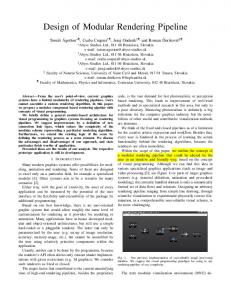
Fig. 8: Simulated results of the digital output of the ADC using the proposed single-phase scheme with VDD =1.5 V. Several simulations were then carried out and many FFTs were extracted from the digital output of the ADC. Figure 9 shows the SFDR for different supply voltages ranging from 1.2 V up to 1.8 V (1.5 V ± 20%) when the ADC switches are driven by (a) the conventional clocking scheme and by (b) the single-phase scheme. It can be concluded from these simulated results that, when the circuit operates at the minimum supply voltage (1.2V) and using the single phase scheme, the SFDR which is dominated by the highest harmonic (usually the third), is improved by about 6 dB. When the ADC operates at supply voltages higher than 1.4 V the SFDR is slightly better (less than 2 dB) when a conventional clock-phase generator is used. However, the
9.3 9.25 9.2 1.8
1.7
1.6
1.5
1.4
1.3
1.2
V DD ( V )
Fig. 10: Expected ENOB values versus supply voltage ( VDD ) when using (a) the conventional and (b) for the single phase scheme. Since the SINAD is dominated by the noise contribution (the ADC was tailored for a maximum SNR of about 60 dB in typical conditions) either using the conventional clocking scheme or the single phase one, the ENOBs is about the same, in both cases, as illustrated in Figure 10. Within the specified supply range the expected minimum ENOB is higher than 9.25 bits since at VDD = 1.2 V the SNR is degraded to about 58 dB due to a 2 dB reduction in the input dynamic range (Ain is reduced from ± 500 mV to about ± 400 mV, i. e. from 2 Vp-p differential to about 1.6 Vp -p). Note that since in the single-phase scheme the clock-phase generator is implemented simply by a couple of CMOS inverters rather than a circuit with many gates (as it is used in
the conventional clock-phase generator), the expected substrate noise introduced will be much smaller. As a direct consequence it is expected, a smaller measured SNR degradation as soon as we have experimental results from silicon. Unfortunately, this claim can not be validated through simulated results.
5. CONCLUSIONS It was demonstrated in this paper that a single phase clock scheme technique can be successfully employed in the design of low-voltage low-power pipeline ADCs. Simulated results using the referred technique were compared with those achieved when the conventional clock scheme is employed. A complete 10-bit 4 MS/s pipeline ADC was then fully designed and simulated, first with all switches driven by a conventional six-phase clock generator and, after, employing a single-phase scheme. The achieved results show the signal integrity and overall performance are preserved and the SFDR is even improved at very low supply voltages.
ACKNOWLEDGMENTS The research work that led to this implementation was partially supported by the Portuguese Foundation for Science and Technology under S2A, SAMBA, SECA and SIPHASE Projects through POCTI and FEDER funding programs.
REFERENCES [1] D. G. Haigh and B. Singh, "A Switching Scheme for Switched-Capacitor Filters, Which Reduces Effect of Parasitic Capacitances Associated with Control Terminals", Proc. IEEE Int. Symposium on Circuits and Systems, Vol. 2, pp. 586-589, June 1983. [2] A. Baschirotto, Rinaldo Castello, “A 1V 1.8MHz CMOS Switched-Opamp SC Filter with Rail-to-Rail Output Swing”, Proc. International Solid-State Circuits Conference, pp. 5859, Feb. 1997. [3] M. Steyaert, et. al., “Switched-Opamp, A Technique for Realising Full CMOS Switched-Capacitor Filters at Very Low Voltages”, Proc. 19th European Solid-State Circuits Conference, pp. 178-181, Sep. 1993. [4] B. Vaz, J. Goes, R. Piloto, J. Neto, R. Monteiro, N. Paulino, “A Low-Voltage 3 mW 10-bit 4MS/s Pipeline ADC in Digital CMOS for sensor Interfacing”, Proc. IEEE International Symposium on Circuits and Systems, May, 2005. [5] B. Vaz, N. Paulino, J. Goes, et. al., “Design of lowvoltage CMOS pipelined ADC’s using 1 pico-joule of energy
per conversion”, IEEE International Symposium on Circuits and Systems, No. 1, pp. 921-924, May 2002. [6] J. Goes, B. Vaz, N. Paulino, H. Pinto, R. Monteiro, A.S. Garção, “Switched-Capacitor Circuits using a Single-Phase Scheme”, Proc. IEEE International Symposium on Circuits and Systems, May, 2005.