Development. Abstract- One of the and Application of a Linear Induction Machine for Instructional. Laboratory Use. J.R. Wells, P.L. Chapman, P.T. Krein.
Development and Application of a Linear Induction Machine for Instructional Laboratory Use J.R. Wells, P.L. Chapman, P.T. Krein University of Illinois at Urbana-Champaign 1406 West Green St. Urbana, IL 61801 Abstract- One of the difficulties of introductorv electric machinery laboratory courses is developing labs that allow students to observe the physics and internal hardware of a motor while it is operating. As a solution to this challenge, this paper will discuss the development of a b e a r induction motor and mount system that allows students to easily visualize the motor while in motion, vary parameters in the motor design to observe their effect on performance, and gain experience with a type of motor that is often overlooked in introductory courses. Introductory laboratory experiments are presented to demonstrate how this experimental hardware can be integrated into a laboratory course.
Sizing the motor to meet educational criteria involved ensuring that the physical size was reasonable and that the machine speed allowed for practical movement and observation on a laboratory bench. A stator length of roughly 35 cm and lamination stacking depth of roughly 5 cm satisfy these criteria. A safe but reasonable to achieve synchronous speed was selected as 1 m/s. Using (l), where V, is the synchronous speed, Tp is the pole pitch, andf is the stator excitation frequency, the synchronous speed is given by:
I. INTRODUCTION Traditional machines courses have a strong focus on rotary machinery. Some popular textbooks leave out the linear induction machine KIM) altogether [l]. The disadvantage of rotary machinery from an instructional standpoint; however, is that viewing and measuring what happens inside the motor and on the rotor is difficult. The open frame linear induction motor presented allows students to gain further insight on practical aspects of machinery. The linear induction motor electrical model is very similar to that of the rotary induction motor. This similarity allows this laboratory demonstration hardware to be easily integrated into a portion of the course on rotary machines. In fact, if a rotary motor is "unrolled", the developed diagram resembles a linear machine. Not only is this a visualization aid, but it can help in understanding relationships between poles, pole pitch, electrical frequency, and mechanical speeds. This paper outlines the general design of a linear induction motor suited for educational use. The discussion begins with an overview of the design strategy followed by details on how each objective was met. Next, the paper presents a suitable motor mount system that allows flexibility and ease of use. Finally, several of the advantages of integration of the linear motor into a teaching lab are discussed.
II. DESIGN DISCUSSION The design process for this project had different objectives than that of a typical induction motor design. Rather than designing to meet specific performance and parameter criteria, we were designing to meet general educational flexibility objectives. The primary objectives were sizing, magnetizing inductance of the stator, physical feasibility, and educational development applications.
0-7803-7262-X/02/$10.00 0 2002 IEEE.
479
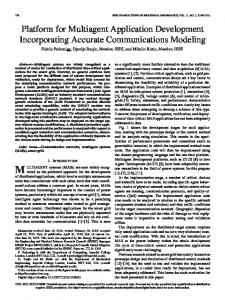
A pole pitch of 1 cm in this equation yields an acceptable synchronous speed of 1.2 m/s for a 60 Hz. stator excitation frequency which is readily available. The number of poles in the motor can then be determined [2]. Additionally, if desired, the motor can be hooked up to a motor drive system for variable speed control. One challenge was achieving a magnetizing inductance that would limit the stator currents to a level typical of teaching labs and consistent with existing equipment. The machine is expected to operate successfully under a variety of geometries including large air gaps between the primary and secondary members and at the most extreme case operating without secondary iron. A no-load current of 3-4 amps and a load current of 5-6 amps were deemed desirable since this is compatible with existing hardware and instrumentation. The primary parameter that limits no-load current of the machine at a line frequency is the inductance. Since the lowest inductance occurs for the case where the secondary has no iron, this case was used to design our machine. Although several models have been proposed to analyze the equivalent air gap of a geometry with teeth [2], there is not a reliable closed form solution for calculating the inductance of a geometry such as the linear motor stator. As such, it was determined that a finite element analysis (FEA) approach would be necessary to accurately determine the inductance [2]. After running several iterations, the design shown in Fig. 1 prevailed. The lamination shown was stacked to a depth of 5.1 cm.
$ 1,
1
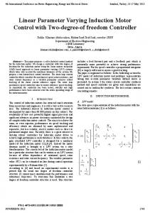
Finally, both portions of the mount are attached using several mounting screws. These sections can be detached allowing a single person to move the entire apparatus conveniently. The prototype mount is shown in Fig. 2. In this picture, a double-sided LIM is shown with an aluminum sheet as the translating member.
il
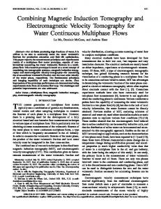
m. EXPERMENTAL RESULTS Only a 30% (as opposed to the typical 50%) fill factor was obtained in the first prototype. As the design is replicated for each lab bench, this minor shortcoming will be eliminated. The prototype stator is shown in Fig. 3. The stator resistance was measured at 0.858 S2 as compared to 0.7127 R that was calculated based on a 35 Fig. 1. Final Dimensions of the Stator Lamination Eighteen gauge wire was selected to achieve enough turns at the desired maximum current (6 A rms) to meet the
inductance specification. The resulting current density of 900 A/cm* would generally be excessive for an enclosed rotary motor, but this motor has an open fiame, is not continuous duty, and has a controlled environment The final design step is to determine the safe operating voltage that will give us the no load current levels that the windings are designed to handle. Based on the FEA and the predicted 60 turns on the stator inductance calculation and 60 turns on the stator, the inductance is 5.61 mH and Using these the winding resistance is 1.2217 R. parameters, the desired operating voltage for a 60 Hz source should be approximately 10 V for a 4 A draw. The voltage is low enough to allow students to handle the motor while in operation without the risk of contacting high voltage electricity. Design of the mount for the LIM involved several challenges including size of the mount system, flexibility, and safety. The mount can be divided into two major components. The first was a double rail that allows fieedom of linear motion for the secondary member. A 30.5 cm by 10.2 cm platform is built onto the double rail. The platform supports a variety of different secondary topologies including simple aluminum sheet (with or without back iron), a wound secondary, or a permanent magnet member. The length of the rails was chosen to be 6 ft. feet as this allows for a 3 ft. long secondary aluminum bar to travel completely past the primary in either direction. Also, this length is widely available and can fit easily on a typical laboratory bench. Adjustable stops were added to the rail system to limit the range of motion when shorter secondary members are in use and also to prevent the secondary platform from falling off the end of the rails. The second component is the mount for the stationary primary members. For flexibility, it was desired that either a single- or double-sided stator could be mounted and have the distance fiom the secondary mount be adjustable. This allows different topologies to be used and allows the air gap to be adjusted for any of the topologies. Again, a dual rail system was chosen. Linear nylon sleeve bearings were chosen for these rails (fiction is not a critical issue).
480
Fig. 2. LIM Motor Mount System
Fig. 3. Stator Prototype
turn winding. This gives approximately a 17 % error which can be traced to the initial calculations not accounting for the end turns. The inductance of the motor was predicted to be 3.507 mH based on voltage and current measurements. Compared to the 1.909 mH as calculated fiom a 35-turn model, this gives an error of 45 %. Again, the difference can be traced to the significantportion of end turns and the large effective air gap. In effect, a 3-D model could be appropriate for this motor due to a significant end turn length as compared to the depth of the motor. The motor still functions desirably despite this shortcoming of the 2-D FEA predictions.
IV.EDUCATIONAL DEVELOPMENT The main focus was to create a laboratory demonstration that was useful for teaching introductory electric machinery. This motor has several advantages over a customary rotary induction motor lab including visualization ease, design accessibility, and parameter variation. The open h m e allows students to observe winding patterns. The use of laminations is clear and allows students to observe the construction of the motor in a hands-on fashion. Some texts begin with a linear motor description to help students visualize the traveling magnetic wave before extending this to the rotary system [3]. In that approach, a hypothetical rotary machine is “rolled out” for easier visualization of winding distribution and h4MF waves. Conversely, the LIM presented can be visualized as a rotary machine by envisioning the motor being rolled in on itself to form a circle. The proposed machine will provide students with a solid feel for how the electric machinery works.
Fig. 4.Single Primary/Secondary(no iron)
Fig. 5. Dual Primary/Secondary (no iron)
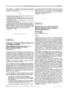
The LIM presented offers an opportunity to integrate real-world design challenges into the laboratory course. For example, the student can verify the some aspect of the geometry and compare this with physical data. This exposes the student to design nuances not typically covered in introductory courses. Finally, one of the greatest advantages that this design offers over typical rotary machinery is flexibility. The linear motor allows the student to vary parameters which are normally fixed and whose effects are not readily visible in the rotary machine. One example of this includes the ability to adjust the air gap between the primary and secondary in order to explore altemate topologies. Another advantage is the ability to easily change the characteristics of the secondary. For instance, one can vary the amount of back iron available, change fiom a wound secondary to a squirrel cage type secondary, or even incorporate permanent magnets into the secondary. The wires on a wound secondary can be accessed with a current probe allowing students to observe the secondary current waveforms not normally accessible in a rotary machine. Currently, we have developed several alternate topologies which can be seen pictured in the following figures. In Fig. 4,the single primary with a secondary with no back iron is shown. In Fig. 5, a dual primary setup is displayed with no iron on the secondary. Finally, Fig. 6 displays a single primary with a secondary including back iron.
48 1
Fig. 6. Single Primary/Secondary (iron)
V. SAMPLELABORATORY EXCERCISES The LIM system presented in this paper was developed with introductory machines course needs in mind. As such, there are three particular types of experiment that should complement a presentation of the introductory theory of electrical machinery. These three experiments include a standard steady state machine characterization, varying the air gap to determine the effect of this parameter on various topologies, and finally comparing the different performance characteristicsof different secondary members. The LIM steady state model is identical to that of its rotary counterpart and is shown in Fig. 7.
If the machine is configured with a wound rotor as the secondary member, we have the ability to measure the rotor currents directly. Students can determine speed of the machine based on the frequency of the rotor currents. Additionally, direct measurement of the rotor parameters (YZ, xz> is possible. These values can then be compared against the values obtained through testing and refemng quantities to the primary. Fig. 7. LIM Steady State Equivalent Circuit An estimate of the parameters shown in the model can be obtained by performing the following tests: 1.
Apply a DC test voltage to the primary windings to determine the primary resistance (TI).
2.
Determine the leakage inductance of the primary (x,) by connecting the three phases of the primary together in parallel and exciting them with a single phase voltage while holding the rotor locked. Setting all input voltages equal in the stationary reference frame creates zero d-axis voltage, zero q-axis voltage, and a non-zero 0-axis voltage. Using the equivalent 0-axis model presented in [3], equivalent impedance is determined allowing for calculation of XI.
3. Perform a locked rotor test on the machine and take several data points while sweeping the frequency. Determine the equivalent impedance of the motor at each data point. Based on the known values of rI and X I , use a parameter fitting technique. Once a methodology is established for characterization of the machine parameters, we can adjust the air gap between the primary and secondary members and observe how this affects our machine parameters. Additionally, the topology of the machine can be varied to observe how different primary and secondary configurations behave differently.
IV.CONCLUSIONS This paper has presented a linear induction motor design and mount system that are suitable for integration into an educational laboratory. Several of the educational advantages of the linear induction machine were presented including visualization ease, design accessibility, parameter variation, and overall system flexibility. Several potential laboratory exercises were presented that utilize some of the unique features of this setup. Further design development will include integration of advanced machinery topics into the laboratory exercises and completion of a permanent magnet secondary. ACKNOWLEDGMENT We thank Todd Walls and Jerry Lloyd at Emerson Motor Company for their support of the project through donation of time and materials and the Grainger Center for Electric Machinery and Electromechanics for providing funding and necessary equipment to complete this project. REFERENCES S. Chapman, Electric Machinery Fundamentals, 3" ed., McGrawHill, 1999. [2] J. R. Wells, P. L. Chapman, P. T. Krein, T. Walls, "Linear induction machine design for insmctional laboratory development", Electrical Insulation Conference and Electrical Manufacturing & Coil Winding Conference, 2001. Proceedings, 2001, pp. 319 -322. [3] Krause, Wasynczuk, Sudhoff, Analysis of Electric Machinety, The Institute of Electrical and Electronics Engineers, Inc., New York. 1995, pp. 3 6 4 , 1 7 6 .
[l]
482