Using UML to Reflect Non-Functional Requirements Luiz Marcio Cysneiros Department of Computer Science University of Toronto
[email protected]
Abstract The way requirements should drive the rest of the software development process has been a subject of many research projects in the past. Unfortunately, all of them focus primarily, when not exclusively, on the functional requirements regardless of the fact that non-functional requirements (NFR) are among the most expensive and difficult to deal with [6] [13] [4][10]. This work evolves out of a previous one [11] and aims at filling this gap, proposing a systematic approach to assure that conceptual models will reflect the NFRs elicited. We focus our attention on conceptual models expressed using the UML [25], and therefore, some heuristics are proposed to make UML suitable to handle NFRs.
1. Introduction The market is increasing its demands for providing software that not only implements all the desired functionality but also some nonfunctional aspects as: cost, reliability, security, maintainability, portability, accuracy among others. These non-functional aspects must be treated as non-functional requirements (NFR) of the software. They, still, should be dealt with from the beginning of software development process [8] [9] [10], throughout the whole life cycle. Not eliciting NFRs or dealing with then later in the process has led to a series of histories reporting failures in software development, including the deactivation of a system right after its deployment [4][18]. Studies point out these requirements as being among the most expensive and difficult to correct [6] [13] [10].
Julio César Sampaio do Prado Leite Departamento de Informática PUC- Rio
[email protected] Only a few works propose some way of explicitly dealing with NFRs under the processoriented approach. From the perspective of the existing literature, most of the work that tackles the use of NFRs during the software development process is still partial [2][3][17]. Chung’s NFR Framework [9] is among the most complete works on NFR and proposes a framework that uses non-functional requirements to drive design and to support architectural design. However, there is still a gap regarding the integration of NFR into conceptual models. Some of our previous works [10] [11] emphasize the premise presented by Chung [9] that the lack of integration of NFR to functional requirements, can result in projects that will take more time to be concluded, as well as bigger maintenance costs. Our work aims at filling this gap, i.e., proposing a strategy that leads conceptual models to reflect the NFRs elicited. It deals with some of the dynamic aspects of the NFR that were not covered in previous works and enhances the integration process presented before [11]. We conducted three case studies to validate the proposed strategy. Two of these case studies were controlled experiments and they were based on the use of the specification for the implementation of the Light Control System for the University of Kaiserslautern [12]. The third case study could be classified as a real life case study and was conducted during the development of a software for a controlling a clinical analysis laboratory. Section 5 will present further details. The results of the case studies suggest that the use of the strategy can lead to a more complete conceptual model as well as to a faster time-to-the market process, since errors due to not properly dealing with NFR, which are usually difficult and time consuming to correct, can be avoided.
Section 2 will present an overview of the entire strategy to deal with NFR, while Section 3 will detail the integration process and Section 4 will present the heuristics on how UML classes may handle NFR. Section 5 will present the results from three case studies used to validate the strategy and Section 6 will conclude and present some future works. 2. An Overview of the Strategy to Deal with NFR
Regarding NFR we understand that, although our strategy may be used to almost any type of NFR, we understand that its results will be more effective when addressing NFRs that effectively demand any kind of action to be performed by the system, and therefore affects the software design. NFRs such as “small learning curve” or “detailed documentation” are not likely to impact on software design and hence will possibly benefit from our strategy only in the elicitation part. On the other hand, NFRs such as “Safety”, “Performance”, “Accuracy” and others, frequently demands the design to be carefully studied in order to satisfice these NFRs. Hence, these NFRs will be more likely the type of NFR that our strategy will be more helpful. As portrayed in Figure 1, we propose to build
We face the software development process as being composed of two independent evolutionary cycles that may be dealt with separately. In our strategy the software development process is carried out through two independent cycles, one regarding the functional aspects of the system and the other the non-functional Sequence Functional View Diagram aspects of the software. Class Use UseCases Cases Since we face Diagram Collaboration them as independent Scenarios Diagram cycles we propose to New Actors establish convergence New Episodes, and New points between both New Classes, Use Cases Resources and New Classes Operations and Actors and Messages cycles. Attributes LEL Through the use NFR and its of these convergence Impacts (Positives and Negatives) points we can express in the functional view NFR all the actions and Graph data that will be necessary to satisfice Non-Functional View the NFRs tackled in the non-functional Figure 1 – An Overview of the Strategy to Deal With NFR view. both the functional and the non-functional views Figure 1 shows the idea of these two views as anchored in the Language Extended Lexicon well as its convergence points. (LEL) [19]. This will lead to a smooth integration The so-called functional view includes some between both views. Therefore, building the of the artifacts commonly used in the software Lexicon will be the first thing to be carried out in development process, while the non-functional this strategy. view uses the NFR Framework [9] as its basic The objective of the LEL is to register the representation. vocabulary of a given UofD1. It is based upon the We will not focus on any particular approach following simple idea: understand the problem’s to build the conceptual models of the functional language without worrying about deeply view. We understand that our strategy may fit to any approach one decides to use. 1 Although our strategy deals with all the “Universe of Discourse is the general context where the software should be developed and operated. The UofD artifacts showed in Figure 1, this article will includes all the sources of information and all known people tackle only the use of UML class diagrams to related to the software. These people are also known as the handle NFR. actors in this UofD.”
understanding the problem [19]. The main objective of the LEL is to register signs (words or phrases) peculiar to a specific field of application. The LEL is based on a code system composed of symbols where each symbol is an entry expressed in terms of notions and behavioral responses. The notions must try to elicit the meaning of the symbol and its fundamental relations with other entries. The behavioral response must specify the connotation of the symbol in the UofD. Each symbol may also be represented by one or more aliases. The construction of the LEL must be oriented by the minimum vocabulary and the circularity principles. The circularity principle prescribes the maximization of the usage of LEL symbols when describing LEL entries, while the minimal vocabulary principle prescribes the minimization of the usage of symbols exterior to the LEL when describing LEL entries. Because of the circularity principle, the LEL has a hypertext form. Figure 2 shows an example of two entries in the LEL. Language Extended Lexicon Symbol
Although the LEL can handle non-functional aspects of the domain, at least the very first version of the LEL is usually mainly composed of symbols related to functional requirements. This is due, in the first place, to the very abstract nature of non-functional requirements. In addition, quality aspects, in spite of its importance, are usually hidden in everyone’s mind. However, it does not mean that the software engineer cannot register information about nonfunctional requirements. A well-defined set of symbols representing the vocabulary of the UofD is a key point to the strategy. Building the non-functional view departs from the use of an existing LEL. In order to aid on this process we have extended the LEL to help NFR elicitation. The LEL is now structured to express that one or more NFRs are needed by a symbol. It is also structured to handle dependency links among one NFR and all the notions and behavioral responses that are necessary to satisfice this NFR. Figure 2 shows these new Language Extended Lexicon Symbol
Category Object
Category Verb
Notions
Notions
Behavioral Responses
Behavioral Responses
Figure 2 – Example of LEL Entries and its Extension to Deal with NFR It is important to make it clear that the LEL is not restricted to holding information related to functional requirements. Its idea is to register the entire vocabulary in the UofD and therefore it might also include the non-functional aspects of the domain.
features of the LEL. We can see in Figure 2 that the symbol Sample belonging to a Clinical Analysis Laboratory information system (Case Study 3 detailed later in Section 5), has in its notions the reference to the need of the NFR Traceability.
It also shows that in order to satisfice this NFR we had to add one behavioral response to the symbol Sample itself (the one that states that one should be able to know where a sample is and where it has been). We also had to add another behavioral response to the symbol Aliquote Sample (the one that states that the system – LIS – should keep a record of what samples were originated from another sample). We can also see beside these behavioral responses a pattern that was included to establish a dependence link between these behavioral responses and the notion that originated its need This will help us to further represent the NFRs and its operationalizations. It also helps when for any reason we need to update the LEL. For example, suppose that reviewing the LEL we decide now that Sample does not need any traceability any more. We should be able to easily see what notions and behavioral responses may be excluded from this symbol or from other symbols. The OORNF tool [21] does that automatically. We have extended the OORNF tool to support these extensions. This tool was originally developed to support the requirements baseline proposed by Leite [20] with some NFR support. The tool has a knowledge base on NFR that can and must be constantly updated. This knowledge base stores a variety of NFRs and some common way to decompose them. The tool brings along with the definition of these NFRs a set of possible conflicting NFR as well as a set of NFRs that may be positively or negatively impacted by this NFR. The OORNF tool also provides support for entering the LEL, scenarios and CRC cards together with a support to create the scenarios from the LEL entries [15] and the CRC cards from the LEL entries and the elicited scenarios [22]. The first step on building the non-functional view will be to enhance the existing LEL with the NFRs that are desired by the stakeholders. To do that, we will run through all the LEL symbols using the knowledge base on NFR present in the OORNF tools to ask ourselves and the stakeholder (whenever possible) if any of the NFRs present in this knowledge base may be necessary to each of the LEL symbols. Each NFR found may be represented in the symbol as showed in Figure 2. After representing the need for an NFR, the software engineer has to ask himself and the
stakeholders what should be necessary to do to satisfice this NFR. Again, the knowledge base in the OORNF tool may be used. All the information that arises from this questioning may be represented in the LEL either in the same symbol or in another symbol if necessary. Coming back to Figure 2, when we get to the symbol Sample (after examining all the previous symbol in the LEL), we asked the stakeholders and ourselves if any of the NFRs in the knowledge base would apply for samples. The answer was that traceability was essential once the laboratory could not afford to lose one sample since drawing a new one could be sometimes almost impossible or at least very painful. We then represented this NFR in the notion of the symbol Sample as seen in Figure 2 and started to ask how could we guarantee this traceability to work. One of the answers was that every time a sample is aliquoted (expression used in this domain that means to create an aliquote, or yet to draw from one recipient to another) this procedure has to be documented in the software so one can know which sample was originated from another sample. We represented this answer as an entry in the behavioral responses of the symbol Aliquote sample and then established a dependency link between this behavioral response and the NFR traceability stated in the notions of the symbol Sample. Although the LEL can handle some representation of the NFR and its impacts, it is not the best tool to deal with them in a more complete way, so one can reason about their interdependencies and conduct the necessary tradeoffs that arises during this process. To fully represent and reason with NFRs we propose to use the NFR Framework proposed by Chung [7] with some minor adaptations. The NFR Framework [23][7][9] faces NFR as goals that might conflict among each other and must be represented as softgoals to be satisficed. Each softgoal will be decomposed into sub-goals represented by a graph structure inspired by the and/or trees used in problem solving. This process continues until the requirements engineer considers the softgoal satisficed (operationalized) [9], so these satisficing goals can be faced as operationalizations of the NFR. Another way of understanding operationalizations is that they are, in fact, functional requirements that have arisen from the
On the top of the Figure 3 (extracted from the Case Study I – A Light Control System), we can see the node that represents the root of this graph represented as Safety [Room], meaning that room is a place that has to be safe regarding illumination aspects. One of the operationalizations that represent part of this NFR satisficing can be seen on the left side of the figure represented by a bold circle denoting a static operationalization. Here, we can see the need of some information in the system that represents the minimum illumination in lux that can be used in a room. Some dotted circles appear on the bottom of the figure representing dynamic operationalizations. One of them, Safety [Room.Malfunction.User get informed], represents that the user may be informed of any malfunction that occurs in the room. The letter S inside each node represents that this sub-goal is Satisficed. The letter P can also be used for those ones that are Partially satisfied or D for those ones that are Denied. Further details can be seen in [11]. It is important to stress that the identifier that appears close to the NFR on the root of the graph (NFR Topic) has necessarily to be a symbol of the LEL. In Figure 3 we see that the root node is represented by Safety [Room], so room has to be a symbol of the LEL. If one cannot find the word or sentence intended to be used as a topic for an NFR either one symbol represented in the LEL has an alias not defined or the LEL is incomplete and should therefore be updated. To build the NFR model we will Safety S [Room] search every entry of the LEL looking for notions that express the need for an NFR. For each NFR found, we must Safety [Room. Safety S [Room. S Malfunction] create an NFR graph expressing all Light scene. Current light scene >= the operationalizations that are Safe Illumination] necessary to satisfice this NFR. At Safety Safety Safety [Room. [Room. [Room. the end of this process we will S S Malfunction. S Malfunction. Malfunction. Motion Detector] Ols] FM Safety therefore have a set of NFR graphs Get informed] S [Room. Light Scene. that will represent the nonSafe Illumination=14 lux] functional aspects of the system. Once we have this set of NFR Safety Safety Safety [Room. S [Room.. S [Room. graphs ready, we have to look for Malfunction of OLS. Malfunction. Malfunction. S All CLG set on] User. Motion Detector. Get informed]v Set room as occupied] possible interdependencies, positive or negative, among NFRs. For Figure 3 – An Example of an NFR Graph example, an NFR pointing out that the software might need a high level
need to satisfice NFR. This can explain why we frequently face doubts about if a requirement is functional or non-functional. In the domain of the laboratory quoted before, we could face a requirement like the one “Samples should be traceable so one can know where this sample is ever”. Some may tend to think this is a functional requirement while, in fact, it is an operationalization of the Traceability NFR [see Chung 00 page 160] for a comprehensive list. In fact, this will be showing how the functional requirement “The software must handle samples” would be constrained by the NFR Traceability. In accordance with [9], for us an NFR has a type, which refers to a particular NFR as for example security or traceability. It also has a subject matter or topic, for example sample as showed in the above example. We would then represent it as Traceability[Sample]. The NFR framework was extended to represent the operationalizations in two different ways. We called them dynamic and static operationalizations. Dynamic operationalizations are those that call for abstract concepts and usually call for some action to be carried out. On the other hand, static operationalizations usually express the need for some data to be used in the design of the software to store information that is necessary for satisficing the NFR [11]. Figure 3 shows an example of an NFR graph where we can see these two types of operationalizations.
electronically signing patient’s report has a of Security may have a negative impact (a negative influence on the operationalizations that negative interdependency) on another NFR like states that in order to satisfice operational Usability, since when one enhances the security restrictions regarding time restrictions to print the controls he/she frequently hurts usability aspects. patient’s report, the system (LIS) should On the other hand, one might face an NFR for electronically sign all the patient’s reports. Performance that claims for the need of saving It is important to clarify that the sub-goals that space used to store some information. To appear in Figure 4 as partially satisficed (P) were operationalize this NFR one option would be to considered satisficed (S) before we carried out the use uncompressed format. This operationalization could eventually contribute positively (a positive interdependency) for another S NFR that calls for a good response time P when dealing with these information. Further details can be seen in [9]. S It is important to point out that all the P effort on NFR tradeoffs due to positive S S and negative interdependencies will P take place in the non-functional view, i.e., using the NFR framework. What S S will be integrated into the functional view will be the result that one gets after all the necessary reasoning on S NFR interdependencies and its P consequences, i.e. the operationalizations. We propose three heuristics to helps Figure 4 – Identifying and Solving Interdependencies us on finding these interdependencies. Among NFR graphs 1- Compare all NFR graphs of pair comparison. These sub-goals were considered the same type searching for possible partially satisficed only after we negotiated with interdependencies. For example, we may the stakeholder to compromise with an put all the NFR graphs that has the type intermediary approach. Safety together to see if there is any This is exactly what is represented in Figure 4, interdependency among them i.e., the patient’s reports will be electronically 2- Compare all the graphs that are classified signed by the system only when all the results are in the knowledge base [21] as possibly within a predefined range considered safe to this conflicting NFRs. For example compare task. graphs of Security with graphs of Although being important, heuristic three may Usability. Frequently to add security to a become inappropriate to be used when the number system we have to sacrifice its usability. of NFR graphs is very large. We do not have a 3- Pair wise all the graphs that were not rule-of-thumb to this number but we have used it compared while applying the above in a case study where we dealt with more then 70 heuristics. NFR graphs and it was still worth to use. During Figure 4 shows an example of a negative this case study the total overhead of using the interdependence found when we were applying proposal was 7% [12] and therefore we think it the third heuristic during one of our case studies. was quite worth to use it. This graph was extracted from a software for To integrate the functional and non-functional clinical analysis laboratory (Case Study III). views we propose a process to drive the This figure shows the pair wising of a graph operationalizations that are represented in the set that deals with operational restrictions that applies of NFR graphs to the functional view. for patient’s report with another one that deals The integration process can take place either in with reliability of tests. Pair wising these graphs the early phases, integrating the NFRs into the use we could see that the sub-goal that deals with the case or scenario models, or later, integrating aspects of how to assure reliability when Manager of the Processing Area
Manager of the Medical Bureau
Reliability [ test ]
Op . Restriction [ Patient’s Report ]
D
Claim [As soon as al the results are ready and reviewed the report must be printed ]
Reliability [ Eletronicaly sign Patient’s Report ]
Time Restrictions [ Print Patient’s Report ]
Reliability [Range to be Eletronicaly signed ]
Time Restrictions [ Results Ready ]
Time restrictions [ Medical Bureau . Eletronicaly Signs Patient’s Report ]
Time restrictions [LIS. Eletronicaly Signs Patient’s Report ]
.
Time restrictions [ Medical Bureau . . Eletronical Signature ]
Time restrictions [LIS. Printing queue for Patient’s Report ]
Reliability [LIS . signs if all results are within range]
NFRs into class, sequence and collaboration diagrams. Notice that we do not propose to deal with NFR elicitation in any of these models. NFR’s satisficing usually requires a very detailed reasoning to reach its operationalizations. Also, one NFR frequently presents many interdependencies with other NFRs. Dealing with these particular aspects of NFRs can be quite difficult to be accomplished directly in use cases, scenarios or even class diagrams. Thus, we propose to deal with NFR in the NFR view using the approach we previously described to build the non-functional view, and then to integrate the operationalizations found into the models used in the functional view. We also propose a traceability mechanism to make it easier to navigate between models. 3. The
Integration Process
diagram. We start the process by picking out a class from the class diagram. We will then search all the NFR graphs from the non-functional view looking for any occurrence of this symbol. For each graph in which we find the name of the class we are searching now, we have to identify the dynamic and static operationalizations in this graph. We have to check if the operations, in the case of dynamic operationalizations, and attributes, in the case of static operationalizations, that belong to the class already fulfill the needs expressed in the graph’s operationalizations. If they do not, we have to add operations and attributes so that this class ends up fulfilling these needs. Notice that addition of new operations may sometimes call for the inclusion of new attributes in order to implement the desired operation. The same applies for new attributes that are added to classes to satisfy static operationalizations. We may often have to add new operations to handle these new attributes. Let us take for example a class named Room from a light control system (extracted from Case Study I detailed in Section 5). We had to search all the NFR graphs in the non-functional view looking for the symbol Room. We could then find the NFR graph showed in the Figure 3 where we can see five operationalizations, four dynamic and one static. The four dynamic operationalizations state
Since functional and non-functional views are cycles that are independent from each other, we need to establish convergence points where the integration of both views can be done, i.e., a way to represent in the functional view the operationalizations found in the non-functional views. The integration method is based on the use of the LEL as an anchor to build both the NFR graph [7] and the class diagram. It means that every root of each NFR graph has to refer to a symbol of the LEL and every class of the class 6 diagram has to be named using a Pick up New decisions on symbol of the LEL. next graph NFRs satisficing that applies NFR The use of the LEL as an anchor Graphs to construct both views will facilitate Static Operationalizations Dynamic Operationalizations their integration. It can also be used NFR Graph where the name 4 to validate both models since, if for of the chosen Analyze possible impacts class appears due to inclusions made in some reason one cannot find a the class diagram symbol of the LEL for naming a 3 5 Evaluate again class, it means that either the symbol Evaluate necessary inclusions s to satisfice this NFR in the is missing in the LEL definition, and class diagram New classes, attributes e therefore should be added to it, or and operations 2 Look for NFRs that any symbol of the LEL has an alias applies to this class New that was not yet considered. Class, Attributes Design and Operations Class Using this anchor, the integration Diagram Pick up a Class process is centered on the search of a Class Do it until there is no symbol that appears in both models classes left to analyze 1 and later in evaluating the impacts of adding the NFR operationalizations Figure 5 – The Class Diagram Integration Process to the class diagram. Figure 5 depicts the integration method for the class
that the software must: 1) Turn all the lights on when a malfunction of the outdoor light sensor occurs; 2) Advise the user of a malfunction of both outdoor light sensor or motion sensor; 3) Set the room as occupied in the case of a motion sensor malfunction and 4) Advise the facility manager (FM) of any malfunction. Now we have to check if any operation in the class Room already performs these actions. If they do not, we should add operations to handle these actions. Notice that if the class that we are analyzing is part of a generalization we have to check if any superclass or subclass of this class does not have operations that satisfy the needed operationalizations. On the other hand, the static operationalization states that there should be an attribute fixing the minimum amount of light in a room as 14 lux. In this case, we have to check if there is an attribute in the class Room to store this information. Notice that what was said before regarding this class being part of generalizations also applies here. It is important to state here that, although we strongly recommend the use of the LEL, this process can be carried out without using the LEL as an anchor. To do that, for every class in the class diagram one should see if there is any graph in the non-functional view semantically related to this class. Of course, if the integration process is carried out this way, we will not have a process as smooth and precise as when we use the LEL. Since the requirements engineer has to be aware of the vocabulary used in the UofD to elicit requirements, we think that the use of the LEL has little impact on the overall overhead.
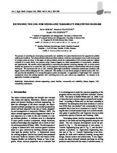
4. Heuristics on how to use UML artifacts to handle NFR We propose four heuristics for introducing NFR into UML diagrams. 1 - Classes created to satisfice an NFR may be stereotyped as . Since NFRs are often more difficult to be on designers’ mind than functional requirements, stereotyping these classes avoid classes to be withdrawn from the class diagram during a reviewing process, because
one could not find any reason why this class must exist. Knowing which NFR was responsible for the inclusion of this class, one has only to examine its operations and/or attributes to find the link to the non-functional view. Figure 6 shows an example of such a class. This class was created when we were analyzing the class Control Panel in the class diagram for a light control system (Case Study II described in Section 5). It is important to make it clear that the creation of a new class to satisfice an NFR will always be a design decision. The software engineer could had chosen, in this case, to add the same attributes and operations present in the class showed in Figure 6 to another already existing class such as the Control Panel class. FMCP Password : int = InitValue
SetPasswd (Password) {Secutiry [FM Control Panel]} AskPasswd () {Security [FM Control Panel ]} ConfirmPasswd() {Security [FM Control Panel ]}
Figure 6– Example of a Class Created to Satisfice an NFR S
S
Security [FM Control Panel. Set Password]
Security [FM Control Panel]
S
Security [FM Control Panel. AskPassword ]
S
Security [FM Control Panel. Password]
Figure 7 – NFR Graph for a Light Control System As we were analyzing what possible NFRs could affect this class, we searched the set of NFR graphs in the non-functional view looking for the symbol Control Panel. One of the graphs we found is showed in Figure 7. We can see in this figure that this graph calls for two dynamic operationalizations: 1) Set Password and 2) Ask Password. These two
operationalizations were necessary because only the facility manager can change some parameters of the system for security reasons. Therefore, there has to be not only a control panel for the facility manager, but also, there has to be a process to check the password in this control panel to avoid non-authorized people to use it. As we did not find in the class Control Panel anything that would satisfice this NFR, we decided to create a new class (FMCP – Facility Manager Control Panel), as a subclass of the class Control Panel. 2 - Beside each operation that has been included to satisfice an NFR we may represent a link to the non-functional view. As in heuristic one, this is to enforce traceability between models, so the designer can easily check nonfunctional aspects whenever he changes anything in this class. To represent the NFR that has originated one operation we use the following syntax: {NFR [LEL symbol] }. Let us take for example the class Room mentioned before. Suppose we create an operation named AdviseUserofMalfuntion in order to perform one of the operationalizations, we should then represent it as follows: AdviseUserofMalfunction() {Safety [Room]}. We present here a different syntax from the one presented in [11] for representing NFR. We have changed it so one can trace exactly which NFR has originated the need for a specific operation. This traceability was not possible in the former work when there were more then one NFR per class. This also holds for heuristics 3 and 4. 3 – We may represent beside an operation any possible pre or post condition that applies to this operation. We will represent these conditions between branches. This heuristic is used to deal with operational restrictions that some NFRs impose. These operational restrictions should be inputted as pre or post conditions to an operation and whenever possible should be stated using OCL [24]. These pre and post conditions can also be stated in a note linked to the class. 4 - Beside each attribute that has been added to satisfice an NFR we may use the same expression we use in the operations to establish a link to the non-functional view. Figure 9 shows an example with the results of applying the heuristics two to four. This figure shows the class LightGroup after the integration
process was carried out during the Case Study II, detailed in Section 5. Figure 8 shows the class LightGroup before we carried out the integration process. LightGroup i_intensity : int i_lightsOn : int valid : boolean s_id : String s_status : String %Dim : Integer LightGroup(s_idGrupo : String) GetId() : String TurnOn() : void ChangeIntensity(i_novaIntensidade : int) : void correctMalfunction() : void TurnOff() : void GetStatus() : String receivemalfunction() : void
Figure 8 – Class LightGroup Before NFR Integration LightGroup i_intensity : real int i_lightsOn : int valid : boolean s_id : String s_status : String % Dim : Integer LuxValue : Integer {Safety [Dim [Illumination Light ]} ]} LastPulse : Hour {Safety [Control System ]} LightGroup (s_ idGrupo : String) GetId () : String TurnOn () : void ChangeIntensity (i_ Newintensity novaIntensidade : real : int ) : void correctMalfunction () : void TurnOff () : void GetStatus () : String receivemalfunction () : void ListenPulse () { Safety [Control System ]} DimLights100%() {Pre: Pulse not received and elapsedtime (LastPulse ) >T4} {Safety [Control System]} SetDimmValue (Percent) {Safety [Control System] Op.Cost [Control System]} CalculateLuxValue () {Safety [ Dim Dimm Light]} GetDimValuies () {Op. Cost [Control System]} GetDimValues SetCLGOn (Number) {Usability [Room Control Panel]}
Figure 9 – Example of Some features added to the UML notation During the integration process, we analyzed each class we had in the class diagram. When we picked out the class LightGroup (showed in Figure 8 above), we searched the non-functional view looking for any occurrences of this symbol. Figure 10 illustrates one of the graphs found.
S
S
S
S .
S
Safety [Dim Light. Illumination >=14 lux]
Safety [Light Group. Calculate LuxValue] Safety [Light Group. LuxValue]
Figure 10 – NFR Graph for Safety applied to Dim Lights
Safety [Control System]
S
Safety [Dim Light]
S
Safety [Control System. Control System Active]
Safety [Control System. Send Signal every T4 Sec]
S
S
Safety [Control System Active. T4 ]
Safety [Control System Active. Light Group. Signal not received past T4 sec]
S
Safety [Control System Active. Light Group. Dimable lights to 100%
Figure 11– NFR Graph for Safety Applied to the Control System regarding a software for a clinical analysis laboratory. Figure 12 shows the class Result to Inspect before the NFR integration. This class represents all the results from tests that come from one or more analyzers (special equipments that perform several tests automatically) and are waiting to be inspected by specialized employees that will analyze if they are reliable or not.
This graph relates to the NFR Safety needed when lights are dimmed. Notice that one of the nodes (sub-goals) that decomposes this graph, shows that in order to be able to criticize if the illumination is greater than 14 lux, the light group has to be able to calculate the equivalent in lux of the percentage set to dim the lights (originally Result to Inspect considered). Since there were no attributes or SampleNumber Test operations in the class doing that task, we added Result the attribute LuxValue and the operation CalculateLuxValue(). InputResult() Another graph found was the one regarding ReadFromAnalyzer() the NFR Safety applied to the Control System that SetResult() AskResult() can be seen in Figure 11. We can see in this figure that to satisfice this NFR there has to be an operation to dim the lights Figure 12 – Class Result to Inspect to 100%, to be executed if the light group does Before NFR Integration not receive a signal from the control Manager of Biochemestry system after T4 sec. Manager of Hematology Again, there were no operations in Security [Input results] the LightGroup class to perform this S Security task, thus we added the operations [aditional Check] S S Security [Regular Check] ListenPulse() and DimLights100%() together with the attribute LastPulse Security if is employee Security necessary to implement the ListenPulse() S [Check is from the same sector [Check if S operation. where the test is processed] result is within permited value ] Notice that beside the operation S Security S Security [Check if Security [Employee. Security S [Test. DimLights100%(), we see a pre Security S employee is Position=“SM”] [Employee. S [Test. authorized ] Safe Range] Sector] condition that states that this operation Sector] will be executed only if this class does Security S [Acess Security Security not receive the signal within T4 sec. S [Minimum] S [Maximum] information] Another example can be seen in Figures 12 through 16. This example Figure 13 – A First NFR Graph Found to be Integrated was drawn from the third case study
Using the integration Result to Inspect process, we searched the set SampleNumber CheckAuthorization() of NFR graphs looking for Test Employee is authorized to Inspect Results Result any occurrences of this CheckResultinRange() InputResult () symbol of the LEL. Figure Result >= Test.NR_Inpect.Min And ReadFromAnalyzer () Result = Test.NR_Inpect.Min And [Results to Inspect]} Result