Block 2 is configured into FASE and the internal pads are configured to connect it to Block ... regional variants of the digital signature algorithms are nu- merous.
FASE: An Open Run-Time Reconfigurable FPGA Architecture for Tamper-Resistant and Secure Embedded Systems Sumanta C HAUDHURI , Jean-Luc DANGER Sylvain G UILLEY, Philippe H OOGVORST GET / T´el´ecom Paris, CNRS – LTCI (UMR 5141) 46 rue Barrault, 75634 PARIS Cedex 13, FRANCE
Abstract The Run-Time Reconfigurable (RTR) feature is highly desirable for flexible and fast self-contained systems. RTR can be achieved on some commercial FPGA platforms. We propose an open solution, called FASE, that allows for finegrain RTR, designed to be more intuitive than currently available solutions. The issues of initializing RTR soft IPcores and a design flow to manage the dynamics of RTR are presented. In the context of secure embedded systems, there is a need for both flexibility and tamper-resistance. However, the robustness level for security constraints is difficult to get and to prove because of the proprietary hidden structures. The FASE architecture addresses these issues. It makes it possible for any designer to implement custom and arbitrary dynamic strategies. We illustrate two case studies: an implementation-level counter-measure against sidechannel attacks and an efficient strategy to thwart fault injection attacks against cryptographic functions.
1. Introduction The hardware reconfigurability is considered when applications are constrained by a high degree of both flexibility and performance. Many academic projects studied RTR architectures, to speed up reconfiguration time and increase the flexibility for reconfigurable computing [1, 2, 3]. Some commercial FPGAs provide dynamic reconfigurability features. XILINX offers partial reconfigurability by columns in its VIRTEXII offer [4]. ATMEL proposes the AT40K and an embedded FPGA in the FPSLIC family based on AVR microcontrollers [5]. Many academics studied optimized tools for fast reconfiguration [6, 7]. However, most innovative architectures like the ATMEL AT6000 and XILINX XC6200 did not get any commercial success and disappeared. With new emerging challenges like security, re-
configurable architectures could have a second wind. Reconfigurability is a good strategy to secure cryptographic accelerators, that are targets of side-channel or fault injection attacks. We suggest, for instance, that a permanent and random change of the configuration is able to conceal side-channel information from the attacker. The main drawbacks of existing reconfigurable architectures are twofold: 1. The architectures are proprietary with many unknowns in the routing structure and reconfiguration hardware. 2. The proposed methods and tools appear to be very constrained by the architecture without improvement possibility. The XILINX architectures are the most constrained because of their coarse-grain column-wise approach. The ATMEL has a fine-grain approach with a reconfiguration at the cell level. However, their legacy Place/Route tool (F IGARO [8]) imposes a static placement of the reconfigured area.Therefore, it seems quite challenging to evaluate the robustness of FPGAs and propose tamper resistant circuits without a close collaboration with the manufacturer. In the security context, the FASE “FPGA Architecture for Secure Embedded systems” project aims at designing an FPGA architecture with RTR capability which meets these requirements: • A fine grain architecture which allows the designer to place/route dynamically the reconfigured area anywhere and at cell boundaries. • An open architecture with detailed and exhaustive specifications of the routing and logic resources. • A simple configuration interface which allows the programmer to build his own reconfiguration strategy. FASE is an offshoot of the SAFE (Secured Asynchronous FPGA for Embedded systems) project [9] which takes profit of asynchronous cells to increase the robustness against side-channel attacks. This project specifies
RST CLK
FASE CONF
ADDR_ROW ADDR_COL ADDR_INTRA_CT[1:0] CONF_DATA
FASE ARRAY
DES
CBOX2 IN
CBOX2 OUT
FASE
°°°
CBOX3 OUT
CONF_CLK
VCI INTERFACE
VCI INTERFACE
VCI INTERFACE
CBOX3 IN
CLB VCI WRAPPER
VCI WRAPPER
VCI WRAPPER
CBOX1 IN bus VCI WRAPPER
VCI INTERFACE
VCI INTERFACE
VCI INTERFACE
CPU
MEMORY
ARBITER
CBOX1 OUT
RST MASK
°°°
Figure 1. VCI interface for FASE ARRAY and FASE CONF.
that the partial and dynamic configuration has to accommodate several modules possibly implemented in different styles of asynchronous logic [10]. It should also be able to modify the design on-the-fly on detection of intrusion. By contrast, FASE is a synchronous FPGA, thus intrinsically unsafe against side-channel attacks. However, its dynamic reconfiguration capability also enables it to implement both preventive and resilience strategies (that are not built-in.) The rest of the article is organized as follows. Section 2 presents the main principles of FASE functional and configuration architecture. Section 3 addresses the issues involved in reconfiguration and presents a typical design flow. In Section 4, two applications requiring a high level of security are presented. Finally, Section 5 draws the conclusion.
2. FASE Architecture 2.1. FASE Overall Architecture and Principles As an embedded FPGA, FASE is designed to be connectable to a system bus. It thus features a VCI [11] interface. The general architecture of FASE comprises of a functional array (FASE ARRAY) and of a configuration controller (FASE CONF), as shown in figure 1. FASE has a generic architecture described in the sequel as per the VPR (Versatile Place-and-Route tool [12, 13]) nomenclature. However, for the sake of illustration, fixed valued are given to some structural parameters. The FASE
CBOX4 OUT
VCI WRAPPER
CBOX4 IN
VCI WRAPPER
switch matrix (SBOX)
Figure 2. The configurable tile (CT) and its components.
array (FASE ARRAY) is a reconfigurable embedded architecture based on four hierarchical objects: 1. The logic element (LE) is composed of a look-up table (LUT) and a D-flip-flop (DFF). A reset mask RST MASK indicates whether the DFF reset line is active or not. 2. The compound logic block (CLB) is composed of several LEs (only one in the sequel.) 3. The configurable tile (CT), depicted in figure 2, is composed of one CLB plus, at its periphery, the following switching components: • The connection box CBOX IN (resp. CBOX OUT) permits the CLB input (resp. output) connections. • The switch box (SBOX) allows the routing between CLBs. 4. And finally, the array FASE ARRAY is an N × N square set of CTs surrounded by 4 × N CTs dedicated to the I/Os (IOBs.) The configuration controller (FASE CONF) is in charge of configuring and initializing any area of the FPGA. The RTR in FASE is based on two configuration levels: 1. first of all, the selection of a specific set of CTs or IOBs amongst the array, and 2. secondly, the CT internal components: CLB (with the RST MASK), CBOX IN, CBOX OUT and SBOX.
...
a(3..0)
1 set
4 LUT
DFF clear
CLK RST RST MASK
y
SEQ/COMB
set clear SET/CLEAR
Figure 3. CLB comprised of (only) one 4 → 1 LE with maskable reset.
A configuration zone corresponds to a set of CT, not necessarily rectangular. The RTR can be applied by reconfiguring subsets of objects inside a subset of CT. For instance, only the RST MASK of the configured area is cleared (so that it is properly initialized) while the rest of the FASE ARRAY remains unaffected by the global reset (because the RST MASK is set.) Detailed examples are given in Sec. 3.
2.2. Functional Architecture The FASE architecture presentation does not insist on any particular performance improvement. The reason is that most optimizations and trade-offs published in the literature can be transposed in a straightforward way to FASE simple and generic structure. 2.2.1. CLB. In addition to the LUT mask, a configuration point SET/CLEAR selects whether the flip-flop should be set or cleared when RST is active. The configuration point SEQ/COMB selects between the “LUT only” or the “LUT + DFF” functionality. The RST MASK is added to selectively initialize CLBs in FASE. This configuration point is addressable independently of the CLB configuration chain. Figure 3 illustrates a CLB composed of one 4 → 1 LE with maskable reset. In all the figures, a solid dot (•) represents a configuration memory point. 2.2.2. Routing Resources. To simplify this section, all the routing tracks are segments of unity length and use a uniform channel width W. We design the input and output connection box flexibilities to be 50% (i.e. the CLB inputs and output connect to 50% of the routing tracks) and we use a Wilton switch box [14] to achieve greater routability. The IOB flexibility is unitary. The global signals RST and CLK are routed separately on dedicated tracks.
VCI interface RAMEN WE ADDR DI DO
Dual-port RAM
M0 — M15
CMD EOC RAMEN WE ADDR DI DO
CLK RST
FASE ARRAY
Figure 4. VCI interface of the FASE ARRAY with functional IO pads.
2.2.3. Functional Interface. FASE ARRAY is linked to the external world via the VCI interface which contains a dual-port RAM accessible by both FASE ARRAY and VCI. Four IOBs are dedicated to control signals: • CMD is used by the VCI interface to start an operation. • EOC is set by FASE ARRAY to signal the operation end. • RAMEN indicates that FASE ARRAY currently accesses the RAM. • WE indicates that FASE ARRAY writes into the RAM. 4 × N − 4 IOBs are available as address and data lines to access the dual-port RAM. For instance if N = 8, 12 IOBs pads could compose the address word and 16 could be the data (8 inputs and 8 outputs). The details of the functional interface is depicted in figure 4.
2.3. Configuration The configurable memory points are programmed via a set of shift registers inside each CT. From a configuration viewpoint, an IOB is considered as being a CT subset. This is because the IOB has no CLB and the number of CBOX and SBOX depends on the IOB location. At power up, the power on reset signal (denoted PO RST) permits to start with all the configuration points inactive. 2.3.1. Configuration Architecture. In FASE, each CT and IOB is addressable by the ADDR ROW and ADDR COL lines, as illustrated by figure 5. Inside a CT, there are four configuration chains selected by the signals ADDR INTRA CT[1:0]. Each chain corresponds to specific CT components:
4
...
CLB(i, j) Active
ROW DECODE
ADDR ROW
W
Connections(i, j) Active.
ADDR INTRA CT[1:0] CONF DATA COLUMN DECODE
4
CLB(i+1, j) Can be reconfigured w/o interrupting CLB(i, j) ... Connections(i+1, j). Can be reconfigured w/o interrupting connections(i, j)
Figure 7. Input connection box: granularity of configuration (W=4, fc in=fc out= 21 ).
CONF CLK
ADDR COL
Figure 5. Address lines and global configuration signals. CONF DATA Chain 0: CBOX1 OUT+CBOX2 OUT+CBOX3 OUT+CBOX4 OUT Chain 1: CBOX1 IN+CBOX2 IN+CBOX3 IN+CBOX4 IN+CLB Chain 2: SBOX
CONF CLK ADDR ROW ADDR COL
...
...
RST MASK ADDR INTRA CT[1:0]
Figure 6. Separately addressable configuration chains of FASE.
1. CBOX OUT, 2. CBOX IN + CLB, 3. SBOX and 4. RST MASK. To avoid electrical conflicts due to shifting of configuration bits along the chain, the CBOX OUT is disabled during the CT configuration period, except if the RST MASK is being configured. This will allow the designer to split dynamically active blocks and inactive blocks without any conflict or operation interrupt. The chain input is CONF DATA and the chain clock is CONF CLK. Figure 6 depicts the architecture of the four configuration chains. The configuration points drive logic directly inside the CLB or drive pass-transistors for the connection boxes and
the switch box. To save a few configuration bits, the connexion boxes use multiplexer switches. The output connection boxes use tri-state buffers rather than pass-transistors to allow high fan-out drive. Figure 7 shows the connection box configuration points. If we consider one LE per CLB, the number of configuration points as in figure 3, the number of configuration points is as follows: • CLB: 18 (M0 – M15, SEQ/COMB, SET/CLEAR), • RST MASK: 1, • CBOX IN: (W × Fc in) × number of inputs, • CBOX OUT: (W × Fc out) × number of outputs, • SBOX: 6 × W, where: W is the number of tracks per row or column, Fc in and Fc out are respectively the flexibilities of the CBOX IN and CBOX OUT. 2.3.2. Configuration Interface. FASE CONF is in charge of the configuration and of the delivery of global signals that are CLK and RST. Like FASE ARRAY, it is connected to the external world via a VCI interface. FASE CONF generates the signals described in table 1: All the signals are global, except ADDR ROW and ADDR COL that are decoded and associated with respectively a specific row and column as shown in figure 5. The FASE CONF reads the instructions and configuration data from the RAM and sends a serial bitstream to the proper address in FASE ARRAY. The basic instruction set is given in table 2.
3. Run-Time Reconfiguration RTR soft IPs or DHPs [7] can be called any time into FASE at the presence of already active blocks. This can be
CLB a(0) CLB a(1)
Table 1. Interface between FASE CONF and FASE ARRAY. Signal Function RST Global reset. It can be masked for each the CT by the RST MASK bit. CLK Global clock. The clock frequency can be adjusted in FASE CONF to satisfy the timings. ADDR ROW Row address. Selects a row among N + 2 for configuration. ADDR COL Column address. Selects a column among N + 2 for configuration. ADDR INTRA CT[1:0] 2 bits CT component address. Selects a specific component set inside a CT. CONF DATA Configuration Data. One bit data to enter the configuration chains. CONF CLK Configuration clock.
Table 2. Instruction set for FASE CONF. Instructions SET ROW SET COLUMN CONFIG C OUT CONFIG C IN CONFIG SBOX
ENABLE RESET
DESELECT START
Function Selects cell address. Selects cell address. Configures input connections. Configures output connections. Configures switch-box connections. Enables/Masks the RST MASK register. Deselects everything. Generates a reset.
RTL Block 1 ............ ............ ............
Block 1 a(0..1) internal pad out
CLB
CLB
CLB
CLB
CLB
CLB
CLB
CLB
CLB
CLB
CLB b(1)
Block 1 b(0..3) internal pad in
CLB b(2) CLB b(3)
SYNTHESIS RTL Block 2 ............ ............ ............
Block 2 b(0..3) internal pad out Block 2 a(0..1) internal pad in
CLB b(0)
CLB
CLB
CLB
CLB
CLB
CLB
CLB a(0) CLB
a(1)
CLB b(0)
CLB b(1)
CLB b(2) CLB b(3)
Figure 8. Design flow outline. achieved by meeting specific RTR rules and methods at 3 hierarchical levels: application, circuit and block.
3.1. RTR at Application Level Dynamic resource management [15] is necessary to efficiently use RTR. RTR modules should be “allocated” before their configuration and “freed” once they are no more in use. This alloc/free information is passed on to the FPGA compilation tool during run-time. This step is necessary as new incoming block depends on the present occupation status of the FPGA. Incidentally the synthesis/place/route tool is analogous to the compiler/linker for microprocessor based systems.
3.2. RTR at Circuit Level The circuit design flow needs to integrate specific interfaces between blocks in order to allow flexibility for the RTR. For this purpose, dedicated CT have to be used as internal IO pads. At the RTL level, they correspond to the entity inputs and outputs as shown in figure 8. This netlist is then placed/routed with VPR. The simulated annealing algorithm in VPR [16] may generate an arbitrary shaped placement in order to minimize the routing resources. However, we constrain the placement such that the CLBs configured as internal pads are always placed at the frontier and the placement avoids the cells already in use as depicted in figure 9. Synchronization issues at initialization between active soft IPs and a newly loaded module is left to the top level RTL designers, for the sake of flexibility. Whether the new incoming block is “ready” or “not ready” can be commu-
Figure 9. Block 1 (black) active, CLBs configured as internal pads are placed at the boundary.
nicated to the active blocks by many protocols. For example, it can consist in polling the status of the new IP block written into RAM, or one of the active IPs may initiate the configuration of this new block. An overview of the RTR design flow is described in the following sequence: 1. RTL code is synthesized to generate soft IP cores connected by CTs configured as internal pads. 2. Block 1 is configured into FASE and initialized, all the internal pads are constrained to be placed at the boundary of Block 1. 3. The placer/router loads the current occupation status of the FPGA and then Block 2 is placed and routed. It is constrained to avoid the already occupied CTs. This can be done in many ways in VPR. One simple method is to set the cost functions of already occupied CLBs equal to infinity. During the placement/routing of Block 2 the router takes into account the positions of the internal pads. 4. Block 2 is configured into FASE and the internal pads are configured to connect it to Block 1. 5. Block 2 is selectively initialized. Figure 10 shows the floorplan result.
Figure 10. Block 2 (gray) is configured, internal pads are configured to connect to Block 1.
3.3. RTR Rules at Block Level 3.3.1. Timing closure. For timing closure placement/routing, a simple strategy consists in considering a safety margin greater than the worst case clock period for the entire system. This basic approach will no more be necessary for future FASE release which will use asynchronous CLBs. The self-timed property of asynchronous calculation will remove this constraint intrinsic to synchronous circuits. 3.3.2. Initialization. Soft IPs have be selectively initialized in FASE without interrupting others. The way to send the RST only to the block which has to be initialized is to use the RST MASK configuration point. While configuring new RTR blocks into FASE, the RST MASK of all active CLBs is masked so that only new configured blocks are initialized. 3.3.3. RTR Sequence. To avoid conflicts during the shifting of the bitstream, each time one of the four chains is selected for configuration, the outputs of the configured CT are disabled. Only the RST MASK configuration point can be programmed without disabling the outputs. Let us assume that Block 1 is active and Block 2 is being programmed. The sequence of reconfiguration of Block 2 is illustrated in figure 11. Block 2 could have a greater or smaller size or even be at
Deactivation of Block 2 CBOX OUT
Configuration of Block 2 CBOX IN + CLB + SBOX
Configuration of Block 2 CBOX OUT
Masking of Block 1 RST
Unmasking of Block 2 RST
Activation of Block 2 RST to start Figure 11. RTR sequence.
a new location. In this case the CBOX OUT of the old location have to be disabled before configuring the new block. Each time a RTR soft IP is freed from the system, all configuration bits in the CT belonging to the freed block are set to 0.
4. FASE Architecture Suitability for Security Applications The key feature of FASE is that it enables the design of robust implementations, which indeed demand an unrestricted access to configuration resources.
4.1. Security Requirements on Hardware The security applications are encountering the problem of the proliferation of cryptographic algorithms. Until the years 2000, the smartcards could perform all the security functions (authentication and encryption) thanks to DES and RSA. The security of those two algorithms is currently questioned, and many alternatives are put forward. Since 2001, DES is officially superseded by the AES, but other candidates are promoted (for instance K HAZAD in Europe.) The same applies to asymmetric encryption primitives: the regional variants of the digital signature algorithms are numerous.
The smartcard industry is thus facing a dilemma: the devices are either cost-efficient or interoperable. The most viable solution thus consists in enabling an applicative agility within the smartcard, using an ad hoc e-FPGA. This way, virtually any algorithm can be implemented with hardware acceleration support: only the credentials (key, seed, etc. material) need to be resident into the smartcard, the algorithms being either downloaded or programmed on-the-fly from an internal ROM. The FASE architecture enables pervasive reconfigurability by the use of hardware accelerated mobile code. In addition, security hardware must also protect itself from implementation-level malicious attacks. The security environment is indeed harsh for embedded systems. Embedded system cannot afford tamper protection used otherwise for critical equipments. It must thus be assumed that invasive attacks [17] are likely to be used against those systems. The security requirements are becoming very stringent: the two examples of sub-sections 4.2 and 4.3 illustrate how RTR can provide an elegant solution to the otherwise difficult problem of mixed passive/active threats [18].
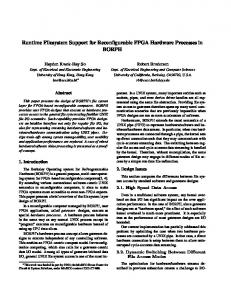
4.2. FASE Usage for DPA-proof Hardware Accelerators The side-channel attacks [19] consist in monitoring the instant power or electromagnetical emissions of a device in order to extract information from the computation internals. The typical protections against those attacks basically boil down to doubling either the execution time (in the case of software) or the implementation area (in the case of hardware) [20]. We propose to use FASE random-access RTR capability to modify the algorithm implementation at every invocation. This strategy makes it impossible for an attacker to collect consistent traces, thus discarding the DPA fundamental hypothesis that execution symptoms can be accumulated for statistical treatments. The implementation mutations can be, in this example of DPA protection, controlled by a random number generator (RNG.) A snapshots of an example DPA protected applications is depicted in figure 12: the fitting function (RNG) is constant and always active and the evolving portion (DPA-proof cryproprocessor) is reconfigured continuously.
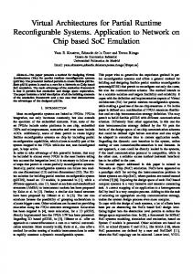
4.3. FASE Usage for FA-proof Hardware Accelerators Fault attacks (FA) [21] intentionally disturb a cryptographic algorithm so as to extract information from the faulty executions. Usual counter-measures against this class of attack consist in adding redundant hardware to detect and possibly correct the faults. However, the main drawback of this approach is that the additional hardware is useless if no
RY
O MEM
MANAGEMENT
U M
M
O
N
LT IP L
TG
O
IE R
M
ER Y
D
ES
zz
UNIT
Figure 12. Example of the use of RTR to achieve a DPA-proof logic block.
Figure 13. Example of the use of RTR to achieve a FA-proof logic block.
fault or light attack occurs. We propose to take advantage of FASE RTR to implement a graded and adaptative faults detection capability. This strategy allows for a cost-effective survivability strategy: as the environment becomes more aggressive, the algorithm implemented in FASE improves its detection codes. In figure 13, a memory management unit (MMU) interfaces a FA-resistant core with the rest of the SoC. The MMU is always active whereas RTR soft IP cores (e.g. DES, RSA using a Montgomery Modular Multiplier) can be loaded into the sytem on demand.
sure constraints. Moreover, with regard to security aspect, asynchronous logic coupled with RTR capability would greatly improve the robustness.
5. Conclusions and Future Research FASE is a different approach towards implementing runtime reconfigurability in FPGAs. In FASE the soft IP cores are not constrained to fit in rows/columns, and there is no necessity of explicit reset signals in the RTL design other than the global reset. However, such explicit initialization could also be done and, in that way, FASE is compatible with applications developed for existing RTR platforms. Although this high granularity of reconfiguration may be used for better utilisation of resources, it may also result in fragmentation, and increases the reconfiguration latency. Possible enhancements could solve the issue of defragmentation and reducing the reconfiguration latency. A FASE planned improvement is to replace synchronous CLB by asynchronous ones in order to cancel the timing clo-
References [1] R. Sidhu, A. Mei, S. Wadhwa, and V. Prasanna. A selfreconfigurable gate array architecture. 10th International Workshop FPL 2000, August 2000. [2] S. Hauck, T. Fry, M. Hosler, and J. Kao. The Chimaera Reconfigurable Functional Unit. IEEE Symposium on FPGAs for Custom Computing Machines, 1997. [3] E. Tau, I. Eslick, D. Chen, J. Brown, and A. DeHon. A first generation DPGA implementation. In In Proceedings of the Third Canadian Workshop on Field-Programmable Devices, May 1995. [4] Xilinx. Development System Reference Guide. http://toolbox.xilinx.com/, 2005. [5] Atmel. Programmable Logic and microcontroller products, 2005. http://www.atmel.com/. [6] B. Donlin and H. Singh. A Dynamic Reconfiguration Run Time System. Proc. 5th Annual IEEE Symposium on Custom Computing Machines, IEEE Computer Society Press, pages 66–75, 1997. [7] E. L. Horta, J. W. Lockwood, D. E. Taylor, and D. Parlour. Dynamic Hardware Plugins in an FPGA with Partial Runtime Reconfiguration. In Design Automation Conference (DAC), New Orleans, LA, June 2002.
[8] K. Nasi, T. Karouhalis, M. Danek, and Z. Pohl. FIGARO – an automatic tool flow for designs with dynamic reconfiguration. International Conference on Field Programmable Logic and Applications, pages 590–593, Aug 24-26 2005. [9] Secured Asynchronous FPGA for Embedded systems. http://www.comelec.enst.fr/recherche/ safe/. [10] N. Huot, H. Dubreuil, L. Fesquet, and M. Renaudin. FPGA Architecture for Multi-Style Asynchronous Logic. In Design, Automation and Test in Europe (DATE’05), volume 1, pages 32–33, 2005. [11] Virtual Socket Interface Alliance – VCI Standard. http: //www.vsia.org/. [12] V. Betz and J. Rose. VPR: A New Packing, Placement and Routing Tool for FPGA Research. Int’l Workshop on FPL, pages 213–222, 1997. [13] V. Betz, J. Rose, and A. Marquardt. Architecture and CAD for Deep-Submicron FPGAs. Kluwer Academic Publishers, 1999. [14] S. Wilton. Architectures and Algorithms for FieldProgrammble gate Arrays with Embedded Memories. PhD thesis, University of Toronto, 1997. [15] G. Wigley and D. Kearney. The Development of an Operating System for Reconfigurable Computing. In IEEE Symposium on FPGAs for Custom Computing Machines, Napa Valley, volume , 2001. [16] A. Marquardt, V. Betz, and J. Rose. Timing-Driven Placement for FPGAs. Int’l Workshop on FPL, pages 213–222, 1997. [17] R. J. Anderson and M. G. Kuhn. Tamper Resistance – a Cautionary Note. In The Second USENIX Workshop on Electronic Commerce, November 18–21 1996. Oakland, California; ISBN 1-880446-83-9. (Online HTML version). [18] MARS project website. http://www.comelec.enst. fr/recherche/mars/. [19] P. Kocher, J. Jaffe, and B. Jun. Differential Power Analysis: Leaking Secrets. Advances in Cryptology: Proceedings of CRYPTO’99, LNCS 1666:388–397, august 1999. Cryptology Conference, Santa Barbara, California, USA. (PDF). [20] L. Goubin and J. Patarin. DES and Differential Power Analysis (The ”Duplication” Method). In Proc. of CHES, volume LNCS 1717, pages 158–172, 1999. [21] H. Bar-El, H. Choukri, D. Naccache, M. Tunstall, and C. Whelan. The Sorcerer’s Apprentice Guide to Fault Attacks. Cryptology ePrint Archive, report 2004/100.