An FPGA Design Flow for Reconfigurable Network-Based Multi-Processor Systems on Chip Akash Kumar1 , Andreas Hansson1 , Jos Huisken2 , and Henk Corporaal1 1 Eindhoven University of Technology, Eindhoven, The Netherlands 2 Silicon Hive, Eindhoven, The Netherlands
[email protected] Abstract
Multi-Processor System on Chip (MPSoC) platforms are becoming increasingly more heterogeneous and are shifting towards a more communication-centric methodology. Networks on Chip (NoC) have emerged as the design paradigm for scalable on-chip communication architectures. As the system complexity grows, the problem emerges as how to design and instantiate such a NoC-based MPSoC platform in a systematic and automated way. In this paper we present an integrated flow to automatically generate a highly configurable NoC-based MPSoC for FPGA instantiation. The system specification is done on a high level of abstraction, relieving the designer of errorprone and time consuming work. The flow uses the state-ofthe-art Æthereal NoC, and Silicon Hive processing cores, both configurable at design- and run-time. We use this flow to generate a range of sample designs whose functionality has been verified on a Celoxica RC300E development board. The board, equipped with a Xilinx Virtex II 6000, also offers a huge number of peripherals, and we show how their insertion is automated in the design for easy debugging and prototyping.
1. Introduction Current developments in modern embedded devices for media systems show a need for integrating a potentially large number of applications or functions in a single device. An increasing number of processors are being integrated into a single chip to build Multi-Processor Systems on Chip (MPSoC). The continuously increasing number of cores calls for a new communication architecture as traditional bus-based architectures are inherently non-scalable, making communication a bottleneck [7, 22]. Networks on Chip (NoC) have emerged as the design paradigm for designing scalable on-chip communication architectures, providing better structure and modularity [7,9,14,22]. Although NoCs solve the interconnect scalability issues, their integration with the processing cores is still a problem, posing a serious challenge for system architects and system integrators in particular [16]. Run-time reconfigurability is becoming increasingly more important with the rising number of applications in
the system. For embedded devices, in particular, it is desirable to use the same hardware, and reconfigure it for different applications at run-time. This also allows the system to accept new applications after it is designed. Further, reconfiguration decreases the cost of the overall system, since hardware is re-used, as compared to designing custom hardware for each different application. Automation is the key to reduce design and verification time. It allows system-architects to traverse the design space in a much shorter time. Further, with increasing heterogeneity in the system, automation of custom IP generation has become imperative in order to limit the effort and time spent. Some work that focuses on generating processing nodes automatically is presented in [8, 12, 19]. Automation of network fabric generation is presented in [5–7, 14]. However, to the best of our knowledge, there is no fully integrated tool-flow for generating network-based MPSoC. In this paper we address the above problems and present a fully integrated flow for a highly reconfigurable NoCbased MPSoC that is verified on FPGA. This flow uses Silicon Hive cores [3] and the Æthereal NoC [13]. On top of that, this is the first flow which allows run-time reconfiguration of both the network and the cores. A run-time flow is also presented for easy debugging and reconfiguration of the system. The design-flow is used to generate several designs that have been tested on a Celoxica RC300E board [2], equipped with a Xilinx Virtex II 6000 FPGA [4]. As a testament to the maturity of the flow, we present two examples, one which has been used in a final-year masters student course to study JPEG decoder partitioning. The rest of the paper is organized as follows. We discuss the related work in Section 2. Section 3 discusses the design flow of the components used in the integrated flow. The integrated design flow to generate reconfigurable architectures is presented in Section 4. The run-time flow for reconfiguration is discussed in the same section. Section 5 presents two of the case studies that have been done with the flow. Conclusions are presented in Section 6.
2. Related Work Significant research has been done to generate and evaluate the designs for the network and the processors respec-
tively. Some of the approaches also aim at validating designs on FPGA. ESPAM, for example, allows MPSoC generation from high level descriptions, and also mapping to FPGA [18]. However, the work uses fixed programmable cores only, and not customized programmable cores. Furthermore, only crossbar, shared bus or point-to-point interconnections are available, and the communication model supports only local memories and no remote write operations. In our design flow, any network topology is supported (not shared bus though), and fully customizable cores are generated. Our flow also supports full reconfiguration of the system; something which is not possible in ESPAM. A good summary of MPSoCs that have been validated on FPGA is provided in [21]. A design flow and methodology for generating application-specific NoCs is presented in [6]. This flow allows automated generation of a NoC,comparable to handtuned solution , in just a few hours. A framework for NoC emulation on FPGA has been presented in [11]. This allows one to explore, evaluate, and compare a wide range of NoC solutions. Two models for designing and implementing NoC are proposed in [5], one written in VHDL for synthesis, and another in SystemC for cycle-accurate simulation. HERMES has also been implemented on the FPGA and uses R8 processors to validate the interconnection network [17]. Relevant NoC research on FPGA has been summarized in [11, 21]. However, none of the works address generation of processing cores together with the network for the entire SoC. On the other end of the spectrum, we have processorcentric design approaches [12, 19]. The design methodologies proposed in [12, 19] rely on automatic processor generation, complete with efficient hardware designs and comprehensive software tools. Similarly, SoCrates [8] aims at reducing time-to-market and verification time. Aforementioned methodologies focus on processor generation only, while in our methodology, the entire NoC-based MPSoC can be customized and generated in a single flow.
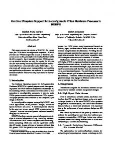
3. Architecture Components 3.1. Processing Cores In our design flow, we use Silicon Hive [3] processing cores. Silicon Hive has an entire tool chain for rapid design of custom cores, varying from RISC to VLIW processors. This is accompanied by a library of function units for designers to choose from and retargetable softwaredevelopment tools. One of the main strengths of Silicon Hive cores lies in the ease with which the cores are generated with design-time configurability with a high-level description in minutes. The cores are generated from a flexible architecture template that can vary the number of processing units, function units, register files, interconnects, and local memories. New instructions, function-units and registers are added with ease as well. Figure 1 shows a flowchart of the Silicon Hive design
#
$
!
"
!
Figure 1. Silicon Hive design flow
flow. It starts with a TIM (The Incredible Machine) description file where one specifies all information relevant for the generation, programming, and simulation of a processor. This encompasses e.g. register file sizes and widths, interconnect, issue slots, operation sets, custom operations, memory and I/O subsystem of the processor. Thus, using the TIM language the entire processor is described in relatively few code lines. TIM also drives the development-tool generator that creates a matching assembler, linker, C compiler, instruction-set simulator, and cycle-accurate simulator. These generated tools are shown in gray in the figure. Once a processor model is created, it is tested with representative programs from the application domain. It provides important feedback to the designer, such as the scheduling of instructions to processor resources (i.e. register files, issue slots, interconnect), which reflects resource utilization. A complete synthesizable RTL hardware description of the processors is also generated. Pre-written blocks of VHDL or Verilog (stored in the component library depicted in the flow) are invoked from the TIM description and the processor is generated.
3.2. Network on Chip Æthereal offers a flexible design flow to dimension and generate application-specific NoC instances and configurations [14]. Figure 2 shows the design flow with all input files at the top. The tools that comprise the flow are shown by boxes and their respective functionality is explained further below. The Æthereal design flow addresses two key problems in NoC-based SoC design: the need for tools to quickly and efficiently generate application-specific NoCs, and the requirement for their performance validation. The starting point of the NoC design flow is the de-
&( " #
Figure 4. Architecture specification example (excerpt).
#$%&
'
#$%&
'
'
!
'
Figure 2. Æthereal design flow
scription of the application’s communication requirements (communication.xml). The NoC hardware is run-time (re)programmable to support different task graphs. Therefore, an application consists of a number of task graphs, or use cases with a number of tasks communicating using the NoC. Figure 3 shows an example specification. A use case is specified as a list of connections. A connection specifies a communication between a master port and a slave port, the required (minimum) bandwidth, the (maximum) allowed latency, and burst size for read and/or write data, and the traffic class being best-effort (BE) or guaranteed throughput (GT).
Figure 3. Communication specification example (excerpt).
The second input file is the specification of the architecture around the NoC. The architecture.xml file, an example of which is shown in Figure 4, contains a list of all IPs connected to the NoC and the IP ports. Each port has a number of attributes, such as protocol (AXI, various DTL (Device Transaction Level) [10] profiles), used to generate the right protocol-conversion shells for network interfaces (NI) [20]. The user also provides the topology to be used e.g. a mesh or a ring. The outcome is a design-time hardware description, topology.xml, containing the number of routers, NIs, and their interconnections. The architecture entities are mapped to the topology using the UMARS [15] tool which also generates the configuration to program the network. The configuration is generated as XML for simulation and in C for embedded processors that program the NoC using memory-mapped IO.
For the network itself, many parameters are specified which can be either customized by hand or left to the tool. Parameters are specified for the NoC (flit duration, number of slots in TDMA table), for each router (arity, best-effort buffer size), and for each NI instance (number of NI ports, connections per port, buffer sizes per connection). To reduce NoC cost, all routers and NIs are dimensioned precisely for the application(s), giving many different router and NI instances per NoC. Once the entire NoC specification is ready, a SystemC model and a synthesizable RTL VHDL description of the NoC is produced, together with area and power estimates of the NoC [20]. It is also possible to analytically compute results for verification that guaranteed traffic meets the previously specified requirements.
4. System-Architecture and Flow !
"
#$% &' ()
&' .
*
+,
-+
Figure 5. Architecture of the reconfigurable system
This section presents the system architecture and the corresponding design flow. An example architecture is shown in Figure 5. The system level hardware description specifies the top-level for the gray boxes shown in the figure i.e. the network and the processing cores used in the design. The figure also shows how the host communicates with the development board. The host is connected to the development board via the USB port, while the protocol used at the system level is DTL. A small library module translates the USB read/write commands to the corresponding DTL instructions. Further, a demultiplexer is used to split between data and configuration ports of the network. This allows the host to act as a DTL master, and to send DTL transactions to configure the NoC and the cores. Similar library modules allow interfacing with on-board peripherals by converting the DTL commands to peripheral specific API. The flow currently supports SRAM, video I/O,
Design-time Configurable Memory Size - Program and Data # and type of interfaces e.g. 2×DTL # of issue slots (ILP degree) Custom operations Register file size and width Network Topology Max buffer sizes for all use cases Max # connections per port Size of slot table System-level Cores used and connection to NoC Peripherals used e.g. video, ethernet Communication Protocol (e.g. MMIO) Run-time Reconfigurable Per core Memory Contents - Program and Data Mode of operation e.g. breakpoint Base addresses Network Configuration of available connections Type and bandwidth of each connection Address map for narrowcast interfaces System-level Address map of the system Per core
Table 1. Example of configurable properties
audio I/O, ethernet, and smart media card. These modules are written in Handel-C since a Celoxica board has been used, and this language provides API for using on-board peripherals. Handel-C channels (implemented as FIFOs) are used to implement clock-bridging to those peripherals that are not in the NoC clock domain. This support is also automated in the flow. Table 1 shows some of the properties that are configurable at design-time and run-time. We have full freedom to generate and use cores ranging from a RISC core to a VLIW core in the same network allowing easy generation of heterogeneous systems. The flow also allows for full freedom at the network level.
4.1. Communication Model Silicon Hive cores use a memory-mapped architecture. Addresses outside the memory range of the core are sent to the external interface unit. Programmers can also explicitly choose to send the data via a particular interface of the core. At the network level, multiple connections can be set up through each interface. Resolution of these connections is done via masking, where a programmable number of bits are used to select which connection to be taken. The system supports three kinds of memory transfers: MMIO (for single word transfers), MMBD (for burst transfers), and PPSD (for streaming data). Every core has its own 32-bit memory map, which need not be aligned with other cores. A physical memory location may be readable by different cores with different addresses.
!
"
"#
Figure 6. Integrated flow for system development (designtime)
4.2. Design Flow Figure 6 shows the integrated design flow. A system level description file (see Figure 9) is used to: 1) generate the VHDL at system level, and 2) instantiate the Silicon Hive cores used in the design and the interconnection fabric. The implementation agnostic system level VHDL “glues” the top-level description of the network and the cores. Description of the latter two components is provided separately as described in Section 3.1 and Section 3.2 respectively. VHDL for the processing cores and the network is generated, together with a simulation model for each component. As one of the contributions of this work, the entire HDL description is generated from a high-level specification in a few minutes. Moreover, a top-level hardware description file is produced from the high-level system specification. This file, referred to as FPGA level HDL in Figure 6, provides access to the peripherals on the board (including the USB interface to host PC), as specified by the user. The automation of this step is another important contribution of this work, allowing a quick and effort-less insertion of the peripherals in the design. An edif file is generated from this HDL file, directly from Handel-C, and is, together with the system level edif file used during Place and Route (P&R) to obtain the bit file (for FPGA configuration). ASIC design can also be produced from the system-level HDL if desired.
4.3. Run-time (Re-)Configuration Flow Figure 7 shows the flow for configuring the FPGA and interacting with the design. The latter is done via the host or via an embedded core in the system that uses a bootROM. First, the bit file produced at the end of the flow in Figure 6 is used to program the FPGA. This instantiates the NoC, the Silicon Hive cores and the on-board I/O modules,
5. Case Studies
' ( %)*
#
! $
"
% $ ' $
& $
$
% $ $
% $
Figure 7. Run-time flow for (re-)configuration
where the latter also enables the FPGA to receive the USB commands from the host. If the host is used for booting, it acts as a DTL master, configuring the network using the configuration code produced from the network description. This sets up the connection from the host to all the processing cores and allows the host to access the memories of the cores. The compiled application code is then uploaded to the respective memories, and the cores are started. Increasing Control from host SoC Mode
Only Observe
Host-boot Mode
Single-step Mode
Figure 8. Different system design options in the flow
Figure 8 shows how the flow allows one to generate designs with varying degree of control from the host. While on one hand, a complete standalone system is generated (defined as “SoC Mode”, presented in Section 5.1), on the other, the entire system is operated in a “Single-step Mode” via the host. The second case-study presented in Section 5.2 uses the host to boot, run and reconfigure the system (defined as “Host-boot Mode” in Fig. 8). It is also possible to generate a design in which the host only observes the state of the system for debugging purpose. In “Host-boot Mode”, the host appears as two DTL master ports from the network side (configuration and the data port), and hence, all the memories in the system are easily read and written from the host. The cores can be inspected and reconfigured at run-time as desired. The same holds for the network as well. This allows the user to change the application running in the system. Since the status and control registers of the core are also visible to the host, they can be modified in order to start/stop the core. Network connections can also be torn-down or set up at run-time. The narrowcast address map may also be reconfigured at runtime. This implies that the data meant for one slave port can be easily redirected to another, without modifying the application code. Similar behavior is achieved by changing the base addresses in the cores. In “SoC Mode”, the above functionalities are achieved through the embedded core for (re-)configuration, instead of the host.
The design flow presented above has been used to generate many architectures. We present here two case studies that demonstrate the ease of using the flow. In both cases the design was synthesized for a Xilinx Virtex-II 6000-FF1152 and verified on a Celoxica board RC300E [2]. This FPGA has 33,792 slices and 144 block RAMs of 18 kbits each. The board itself has 4 SRAM memory banks of 8 MB each, providing a total of 32 MB. It also has two ethernet ports, two DVI I/Os, two S-Video I/Os, AC’97 compatible audio I/O and an on-board LCD screen among others peripherals.
5.1. SoC Mode Design This case study employs a simple design with three cores, a single router and two NIs. The cores used in this exercise were customized for 4 issue slots, 32-bit data path, with one master and slave port for communication. The size of memory for data and program was set to 16KB and 32KB respectively. This design is an example of the left end of the spectrum in Figure 8 (“SoC Mode”). and uses an embedded core for booting and system configuration. Two other cores are used for processing. For sake of simplicity, the same type of core was used for both configuration and processing. The network flit clock is set to 240 ns using a native flit size of three words and 32-bit data width, delivering a raw bandwidth of 50 MB/s. A simple producer-consumer application was written on each processing core to test for functional correctness. Connections were therefore, set up from the master port of each processing core to the slave port of the other one, resulting in two connections. The bandwidth for each of these connections is set to 2.5 MB/s and both have GT traffic. This design uses 65% of entire FPGA area in terms of slices. Each processor takes 20%, while the network uses 5%. A total of 77 block RAMs are used. The design is optimized for area and tested at 12.5 MHz. The bandwidth achieved is 2.5 MB/s per connection, as desired.
5.2. Host-boot Mode Design The second example has an architecture similar to the one shown in Figure 5, and is designed in “Host-boot mode”. In this design there are three processing cores, a shared memory of 24 MB (3 banks), an audio output, and a video output (1 bank as frame buffer). The processing cores used in the design are customized with 1 logic slot, 1 DSP slot, 1 DTL master interface and 1 DTL slave interface. The size of memory for data and program is set to 16KB and 32KB respectively. The screen on the board is accessed as a 16-bit frame-buffer and uses one bank of SRAM on the board. Each pixel is represented in RGB format using 5 bits each for red and blue, and 6 bits for green. The audio output port is configured for a sample rate of 48 KHz. Figure 9 shows a snippet of the system specification file. As seen, the specification step is very simple and fast. It takes us only a few minutes to specify system-architecture.
System NoC_IOs { node core1 (noc.ni1.pi); node core2 (noc.ni2.pi); node core3 (noc.ni3.pi); node extmem (noc.ni4_0.pi); node video (noc.ni4_1.pi); node audio (noc.ni4_2.pi); node host; network noc (host.cfg, host.dat, core1.pi, core2.pi, core3.pi); };
Core 3 Network
Figure 9. System specification example (excerpt).
Masters Host Core1 Core2 Core3
Slave Ports Core 1 Core2 Core3 Memory Audio Video BE BE BE BE BE BE GT GT GT GT GT GT
Core 1 Core 2
Table 2. Network connections in “Host-boot mode” case study
A number of different network topologies have been evaluated for the design, ranging from a three router ring network, a 2×2 mesh, to a single-router network with five NIs. With all the on-board peripherals included (USB, video, audio), only the latter fits in the FPGA resources. The network runs with a flit clock of 120 ns, offering 100 MB/s of raw bandwidth. As mentioned in the run-time flow, the configuration of the network and the cores in this design is done via the host. Connections are set up as specified in Table 2. In total there are 6 GT connections of 8 MB/s each and 6 BE connections. The design occupies almost 100% of the FPGA area leaving only 2 slices unused. This is equivalent to about 6.59 million gates. The maximum frequency at which the design runs is 25.29 MHz and it has been successfully tested at 25 MHz. The floor-plan for this design is shown in Figure 10. The 3 cores and the network are easily seen. The individual NIs and the Handel-C modules to convert DTL to peripheral specific API are not easily visible since they do not occupy significant area in the design. This design is also used by final year masters students in our department to study partitioning of a JPEG decoder. Shared memory is used to store the input image, while the screen was used to display the output of the decoder. The decoder itself is mapped on the Silicon Hive cores used in the design. More details on the course can be found at [1].
6. Conclusions In this paper, we have presented a fully integrated toolflow for a completely reconfigurable NoC-based MPSoC. The flow allows one to configure everything from the size of register files in the cores to buffer sizes in the NIs to the architecture and address map of the system - all in the same flow, and generate a bit file that can be directly tested on the FPGA. Furthermore, we present a run-time flow that allows easy debugging and reconfiguration of the system via
Figure 10. Floor-plan of FPGA for the “Host-boot mode” case study
a host. The designs produced have been verified on a Xilinx Virtex II 6000 FPGA development board, and two such case studies are presented. The design complexity is, however, limited by the slices available in the FPGA. A bigger FPGA allows us to explore more network topologies and have more cores in the design.
References [1] 5kk53 course webpage. Available from: http://www.es.ele.tue.nl/education/5kk53, 2006. [2] Celoxica. Available from: http://www.celoxica.com, 2006. [3] Silicon hive. Available from: http://www.silicon-hive.com, 2006. [4] Xilinx. Available from: http://www.xilinx.com, 2006. [5] T. Bartic et al. Network-on-chip for reconfigurable systems: From high-level design down to implementation. In Proc. FPL, 2004. [6] L. Benini. Application specific NoC design. In Proc. DATE, 2006. [7] L. Benini and G. de Micheli. Networks on chips: A new SoC paradigm. IEEE Comp., 35(1), 2002. [8] M. Collin et al. SoCrates - a Multiprocessor SoC in 40 days. In Proc. DATE, 2001. [9] W. J. Dally and B. Towles. Route packets, not wires: on-chip interconnection networks. In Proc. DAC, 2001. [10] Device Transaction Level (DTL) protocol specification. version 2.2, 2002. [11] N. Genko et al. A complete network-on-chip emulation framework. In Proc. DATE, 2005. [12] R. Gonzalez. Xtensa: a configurable and extensible processor. IEEE Micro, 20(2), 2000. [13] K. Goossens et al. Æthereal network on chip: concepts, architectures, and implementations. IEEE Design and Test of Computers, 22(5), 2005. [14] K. Goossens et al. A design flow for application-specific networks on chip with guaranteed performance to accelerate SOC design and verification. In Proc. DATE, 2005. [15] A. Hansson et al. A unified approach to constrained mapping and routing on network-on-chip architectures. In Proc. CODES+ISSS, 2005. [16] G. Martin. Overview of the MPSoC design challenge. In Proc. DAC, 2006. [17] F. Moraes et al. HERMES: an infrastructure for low area overhead packetswitching networks on chip. Integration VLSI J., 38(1), 2004. [18] H. Nikolov et al. Efficient automated synthesis, programming, and implementation of multi-processor platforms on fpga chips. In Proc. FPL, 2006. [19] C. Rowen and S. Leibson. Flexible architectures for engineering successful SOCs. In Proc. DAC, 2004. [20] A. R˘adulescu et al. An efficient on-chip network interface offering guaranteed services, shared-memory abstraction, and flexible network programming. IEEE Trans. on CAD of Int. Circ. and Syst., 24(1), 2005. [21] E. Salminen et al. HIBI-based multiprocessor SoC on FPGA. In Proc. ISCAS, 2005. [22] M. Sgroi et al. Addressing the system-on-a-chip interconnect woes through communication-based design. In Proc. DAC, 2001.