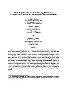
Fast algorithms for the simulation of polygonal particles
Recommend Documents
clusions are given in section 5. 2. Blurred segment. The notion of blurred (or fuzzy) segments relies on the arithmetical definition of discrete lines [10] where a ...
present an Adaptive Importance Sampling (AIS) technique inspired by statistical physics called Fast Flat Histogram. (FFH) method to evaluate the performance of ...
Fast Algorithms for Generating Delaunay. Interpolation Elements for Domain Decomposition. Philip L. Bowers. Department of Mathematics 3027. Florida State ...
connectivity and the the vertex locations in the intermediate model. This approach is memory efficient, allowing the simplification of very large polygonal models, ...
Jul 14, 2016 - We study the fixed design segmented regression problem: Given noisy samples from a ...... Fast, provable algorithms for isotonic regression in.
Feb 1, 1992 - A wide variety of problems can be expressed as fractional packing problems. ..... Ax 5 Xb. We shall use the notation (x, A) to denote that X is the minimum value corresponding to x. ... Hence, X 2 (1 - 3d-1c&d/(ytb) 5 (1 - 3+9* 5 (1 + 6
The columns of ˜Q(2) then form an orthonormal basis ...... 780–804. [23] G. Golub and C. van Loan, Matrix Computations, 3rd ed., The Johns Hopkins University.
of points that exist in only one set increases, the likelihood of missing the correct match will also increase. If point features of different types from the images can ...
in contact result in small changes in the particle shape, particularly around the points of contact. ... mined simply by knowing the position of the center and.
J. E. Walter is with the Computer Science Department, Vassar College, ... The com- plete interchangeability of the robots provides a high degree of system fault ...
1Our algorithms do not address the issue of fault-tolerance (see Section VII for further ... heuristics are used to find a near-optimal probabilistic solution .... 2) In a round, a module is capable of moving to an adja- cent cell. (see Fig. ..... st
Published online 17 April 2007 in Wiley InterScience ... This limit state resembles the so-called critical state of soil mechanics, except for some stress ...... of rheological laws in incremental form and the main classes of constitutive equations.
Sep 3, 2002 - from the first path is interfered by the previous OFDM symbol ...... x x. (3.48) is the K x K correlation matrix of the array sensor inputs ...... Transmission Systems,â Proceedings of IEEE VTC'98, Ottawa, Canada, pp.2774-2778,.
Apr 7, 2011 - graph such that yi = 1 if i is in the MIS and yi = 0 otherwise, then it may be sufficient to determine yi1 ,...,yik for a small number of k vertices.
Paul S. Heckbert and Michael Garland. 1 May 1997. School of Computer ...... et al. or Soucy-Laurendeau. Hoppe-DeRose-Duchamp-McDonald-Stuetzle. 93.
Jan 27, 2008 - known benchmarks including shocks, the Weibel instability, Landau ... ven), by the European Commission through the SOLAIRE network ...
Kendall's Tau. David Christensen. EMB, Link House, Great Shelford, Cambridge, England. CB2 5LT. Summary. Traditional algorithms for the calculation of ...
Computation of Graph Edit Distance. Michel Neuhausâ, Kaspar Riesen, and Horst Bunke. Institute of Computer Science and Applied Mathematics, University of ...
The algorithms devised in this way, applied for the solution of a finite linear system, or for ..... P of (1.3), a sequence fP(n)gn of stochastic (n + 1) (n + 1) block matrices, whose probability ...... 9] A. Berman and R. J. Plemmons. Nonnegative ..
nodes have different transmission ranges; n is the number of nodes in the ..... Graham's list scheduling algorithm according to the Longest. Processing Time ...
In this paper, a research is described three proposed chaos encryption techniques for multimedia transmission over Mobile. WiMax physical and MAC layers.
Fast algorithms for the simulation of polygonal particles
To correct the order in the list of the boundaries one uses âinsertion sortâ. Insertion sort is very fast for nearly sorted lists [6] and performs only local exchanges.
c Springer-Verlag 1999 Granular Matter 2, 35–43
Fast algorithms for the simulation of polygonal particles Alexander Schinner
Abstract Three algorithms to speed up discrete-element simulations for granular matter are presented in this paper. The first algorithm allows to determine neighborhood relations in polydisperse mixtures of particles of arbitrary shape, either discs, ellipses, or polygons. The second algorithm allows to calculate the distance of two polygons in constant time, independently of the complexity of the shape of the polygons. This makes fast simulations of polygonal assemblies possible. The third method is a special type of parallelization technique which is optimized for workstations with shared memory.
1 Introduction The discrete element method (DEM) is a modeling technique for analyzing complex systems of individual particles. The method is closely related to molecular dynamic simulation (MD). The main difference is the kind of interaction, MD simulations typically have a long range interaction resembling atoms or molecules, DEM short range due to steric hindrance resembling e.g. granular media. For each element Newton’s equations of motion are solved. Therefore one has to calculate the forces acting on each particle. In general this is the sum of single particle forces like gravitation and forces due to particle–particle interactions. Then the basic structure of such a simulation is: 1. Find all pairs of colliding (interacting) particles at a given time step 2. Calculate forces for each interacting pair of particles 3. Solve Newton’s equations of motion 4. Goto 1. Steps 1 and 2 can become a bottleneck of the simulation, if inefficient algorithms are used. Received: 7 April 1999 Alexander Schinner Otto-von-Guericke-Universit¨ at Magdeburg, Universit¨ atsplatz 2, D-39016 Magdeburg, Germany e-mail: [email protected] I would like to thank Hans-Georg Matuttis and Stefan Luding for fruitful discussions.
The simulation of granular matter should reproduce as many different experimental setups as possible and should represent reality as closely as possible. A realistic simulation should be able to predict observables that are not measurable by experiment. Until now, most simulations work with two-dimensional discs. This gives fast calculation of the distance of two particles. However, round particles have some drawbacks. If rotation is allowed in the simulation, round particles can roll very easily. This changes the bulk mechanical behavior. The angle of repose for heaps built from round particles is much lower than for realistic rough particles. There are approaches using elliptic particles, which give more realistic simulations. Both for microscopic (force network) and for macroscopic (stress–strain relation) observables Ting [1] showed that there are important differences between round and elongated particles. However, for calculating the collisions of two ellipses, one has to find roots of polynomials. In general these polynomials are ill conditioned, with spurious or inaccurate solutions for the contact points, which leads to numerical problems. Potapov and Campbell described a method for particles composed from segments of circles [2]. These particles can approximate regular polygons well, the number of corners corresponds to the roughness of the particle; however irregular shapes do not seem to be possible. As the paper shows only monodisperse particles with an equal number of corners it may be difficult to expand this algorithm to polydisperse mixtures of particles with arbitrary roughness. A natural and flexible approach is to represent particles and walls by an arbitrarily shaped convex polygon. As can be seen in Fig. 1, miscellaneous setups can be realized. By using the algorithms presented in this paper, simulations using polygons are not as time consuming as one might assume.
1.1 Collision detection The fast determination of all colliding particles is a difficult task. Techniques like Verlet-tables or neighborhoodlists are most efficient for monodisperse simulations for polydisperse setups they become inefficient. In section 3 the incremental sort-and-update algorithm will be explained. The scaling of the time consumptionby this
36
The combination of the incremental sort-and-update algorithm and the closest-feature algorithm does not depend on the particle size. An arbitrary mixture of particles of any shape and number of corners may be simulated without loss of efficiency. The algorithms are independent of the force law, as long as there is a maximum range of the interaction. The parallelization for these algorithms is explained as well. Of course these techniques can also be used to speed up standard simulations. 3 Collision detection with the Incremental sort-and-update algorithm Fig. 1. Dynamic and static simulations using polygons
˜ ) where N ˜ is the number of partimethod is “ideal” O(N cles which have changed position, for every size distribution the algorithm is “optimal”. For static configurations ˜ goes to zero. N This algorithm is not only applicable to polygonal particles in combination with bounding boxes, but can also be used to speed up simulations of any particle system with interactions of finite range. 1.2 Polygonal particles The closest-feature algorithm is highly optimized for simulations of polygonal particles. It is possible to calculate the shortest distance between two polygons in constant time, independent of the complexity of the particles. Moreover, if the particles are overlapping one obtains the pair of intersecting edges “for free”. 2 Overview Discrete-element simulations of granular matter open a window to a variety of fascinating and interesting phenomena. Unfortunately, these methods are often time consuming, so a lot of computational power is needed to expand the simulation to large numbers of particles and long simulated times. This paper will focus on two-dimensional simulations of granular matter. There are standard techniques, which are used to reduce computing time. However, these methods are restricted to special cases and reduce the generality of the physical system. In this paper faster algorithms will be presented which do not have these restrictions. The underlying idea is to combine two algorithms in the collision detection. The first algorithm (incremental sort-and-update algorithm) reduces the number of “possible collisions”, the second one (closest-feature algorithm) detects “non colliding” pairs of particles. As result one obtains a list of all colliding particles.
Checking all pairs of N particles would require N 2 tests. Because the interaction is short-ranged, most of these pairs will not contribute to the force calculation. So the most important task for an efficient simulation is to reduce the computing time dependency below O(N 2 ) in order to speed up the simulation of large systems. 3.1 Standard solutions One standard method is to use neighborhood lists [3]. The simulation area is divided into small areas using a grid. For each particle, the mesh of the grid in which its center of mass is located is determined. The time consumption to locate a particle will be denoted by tmesh , the average number of particles inside of a mesh is Nmesh , the time to check whether a pair of particles collides is tcol . After a location step each particle is checked against all particles in the nine neighboring meshes, including the own, this takes the time 9 · Nmesh · tcol . The total time needed to detect all collisions is N (tmesh +9·Nmesh ·tcol ). This means that the number of particles per mesh should be as small as possible. However, if the mesh size becomes too small, collisions may be undetected, which is unacceptable for a physical simulation. For small mesh sizes, one also has to look for particles in next-neighboring meshes. For dense monodisperse systems Nmesh can get close to unity (Fig. 2a), the total computing time is N ·(tmesh +9·tcol ). Hence the algorithm is most efficient if the size of the mesh is as small as possible, about the size of the largest particle in the simulation. A problem arises if one has a polydisperse mixture of particles. The size of the mesh is adapted to the largest particle, as one can see in Fig. 2b. The smaller particles in the neighboring cells increase the average number Nmesh . In the worst case Nmesh ∼ N and the algorithm becomes very inefficient. 3.2 Bounding boxes The first step is to hide the particle shape from the collision detection algorithm. This is done by the use of bounding boxes, which hide the complexity of an arbitrarily
37
Fig. 2. a Mesh on a monodisperse mixture of particles, b Polydisperse mixture of particles y
Particle
Bounding box
ey
by bx
ex
x
Fig. 3. A polygonal particle and its bounding box. The bounding box technique can also be employed for discs or ellipses
shaped particle by a simpler shape, which is designed to be optimal for a given algorithm (Fig. 3). For the algorithm presented here, the bounding box is a rectangle, whose edges are parallel to the axes, the values bx , by , ex and ey are sufficient to describe the box. A bounding box BA for a particle A is every area for which A is totally contained in BA . If two bounding boxes BA and BB of two particles A and B do not overlap then the particles itself do not overlap. Checking two bounding boxes first and only calculating the overlap for the polygons if the bounding boxes collide saves a lot of time. Although the bounding boxes can speed up the pairwise test, one does not get rid of the time consumption proportional to N 2 , all pairs of bounding boxes have to be tested. 3.3 Incremental sort-and-update algorithm The task for the “incremental sort-and-update algorithm” is to reduce the time consumption to O(N ) for arbitrary kind of particles. The particles shape is “hidden” due to the bounding boxes. The particle size does not matter and polydisperse systems can be simulated efficiently. To explain the algorithm, the one-dimensional case will be treated first. Then the extension to higher dimensions is described.
3.3.1 One dimension In the one-dimensional case, the bounding boxes are intervals on the X-axes. Three bounding boxes can bee seen in Fig. 4, the list of bounding box collisions contains only the pair of box #1 and box #2. The beginnings and endings of the bounding boxes are marked on the axis. One has the sorted list of these variables b1 , b2 , e1 , e2 , b3 , e3 . In general, if 1. 2. 3. 4.
bm ≤ bn bm ≤ bn bn ≤ bm bn ≤ bm
≤ em ≤ en or ≤ en ≤ em or ≤ em ≤ en or ≤ en ≤ em ,
then the two bounding boxes #1 and #2 collide. From a sorted list of all bi and ei one can check for the conditions to be fulfilled and thus determine all collisions. This information can be used by a “sort and sweep” algorithm to generate a list of collisions at startup [4, 5], this method is not very good, since it is inefficient for increasing number of collisions. In order to avoid this, one can utilize that for a physical system in a molecular dynamics simulation the particles move a rather small distance between two steps. Instead of generating a new list of colliding bounding boxes for every step of the simulation, the old list is corrected. Fig. 4 shows such a situation after the bounding boxes have moved a small distance. The values for b1 , e1 , . . . all have changed, but the new order of the boundaries in the sorted list is nearly unchanged, only two pairs of boundaries have to be exchanged. As the ordering of the boundaries contains the complete information on all contacts, each change in the ordered list means a change to the list of collisions. Hence the information about the last step is nearly correct and can be used as starting point for the current time step. To correct the order in the list of the boundaries one uses “insertion sort”. Insertion sort is very fast for nearly sorted lists [6] and performs only local exchanges. However, every exchange in the sorted list of boundaries can change the overlap status of the two affected bounding 2 1
b1 b2
3
e1
e2
b3
t
e3
x
2 1
b2 b1
3
e1 b3 e2
t+1
e3
x
Fig. 4. Moving bounding boxes, the position of the upper and lower points of the intervals are shown
38 Table 1. This table gives the rules for the repeated sorting of a list of boundaries in one dimension. If, for example, two “beginnings” are exchanged during the insertion sort run, the list of collisions is unchanged t bm bn em en bm en em bn
⇒ ⇒ ⇒ ⇒
t+1 bn bm en em en bm bn em
Collisional state collision remains in list collision remains in list collision is removed from list collision is added to the list
boxes. The rules for the exchanges are described in Tab. 1. These tests have to be performed for every exchange during the resorting. The execution of the incremental sortand-update algorithm for the example in Fig. 4 is shown in Tab. 2. Since the time consumption of insertion sort is proportional to the number of the elements for nearly sorted lists, the list of all collision is updated in approximately N steps. 3.3.2 Two dimensions Expanding this algorithm to two dimensions is straightforward. The projection of each bounding box onto the axes gives two intervals with four boundaries bx , by , ex , ey . Two bounding boxes are colliding if and only if the corresponding intervals collide for both axis. Once again, the collision status can change only if two boundaries are exchanged during the resort. The incremental sort-and-update algorithm is executed separately for both axes. If there are exchanges of two boundaries, the information on the overlap status on the other axis becomes important. If the corresponding intervals for the other axis do not collide, no collision can occur. If the intervals on the other axis collide, changes in the position can have an effect. What has to be done can be seen from Tab. 3. If one exchanges 2 upper or lower points, the list of collision remains unchanged as in the one-dimensional case. If one has b1 e2 ⇒ e2 b1 one can simply mark this pair as “non colliding”, again without having a look at the other axis.
Table 3. This table gives the rules for the repeated sorting of a list of boundaries in two dimensions. If, for example, two “beginnings” are exchanged during the insertion sort run, no change to the list of collisions has to be done irrespective, of whether the boxes are overlapping on the other axis t bm bn em en bm en em bn
t+1 ⇒ ⇒ ⇒ ⇒
b n bm en em en b m bn em
Non-overlapping intervals on the other axis unchanged unchanged unchanged unchanged
Overlapping intervals on the other axis unchanged unchanged remove collision add collision
Only for the last case, one has to check the position of the bounding boxes for the other axis. If there is also an overlap, the collision is detected and must be inserted in the list of collisions. The time consumption is twice as high as for the one dimensional case but again proportional to the number of particles, N . The algorithm does not depend on the particle size, so that polydisperse mixtures of particles can be simulated easily.
3.4 Examples For the sake of completeness two of the worst cases for the incremental sort-and-update algorithm in combination with bounding boxes will be discussed: In Fig. 5, a configuration of bounding boxes for elongated particles is displayed. The large particle is marked as a possible colliding partner with all the small ones. However, the incremental sort-and-update algorithm will not need any additional time to update the collision list. The additional time to check whether the large particle and all the small ones intersect is small due to the closestfeature algorithm presented in chapter 4. In contrast to the neighborhood lists no additional collision detections between the small particles are necessary. Fig. 6 shows the worst case for the underlying sorting algorithm. The order of the beginnings and the endings are
Table 2. This table gives the complete incremental sort-and-update algorithm for the example shown in Fig. 4. The concept for the insertion sort is simple. There is a sorted and an unsorted pile of elements. One element of the the unsorted pile is taken (actual element) and compared with the elements (elements, one compares with, are underlined) of the sorted piles. One starts with the rightmost element, if the actual element is larger than the element it is compared with, the correct place in the sorted list is found, it is inserted there. If the actual element is smaller, one exchanges the elements and has to update the list of collisions Step 1 2 3 4 5
Changes in collision list none – – add collision (2;3) –
39
polygons which is a necessary part of the overlap determination. . . ” [2]. In this section it is shown that this is not correct, one can simulate polygons efficiently, and a realistic modeling using polygonal particles is possible. The closest-feature algorithm presented in this chapter calculates the distance during the simulation in constant time, independent of the number of sides of the particles. The method originates from virtual reality and motion planning [8] and is adapted to two-dimensional granular simulations.
Fig. 5. This figure shows the problem that can arise if an elongated particles spans a large bounding box
1
1 2
2 3
3 4
b1 b2 b 3 b 4
e1 e2 e3 e4
4 x
t
b4 b3 b2 b1
e4 e3 e2 e1
x
t+1
Fig. 6. Two time steps for which the order of the particles is reversed
reversed. This leads to a sorting time proportional to N 2 if only this tower is simulated. For practical applications this case can be neglected1 . It is not likely that such a setup will occur during a normal simulation as whenever the particles need more then one step of time to exchange b and e, the algorithm again behaves well. Second, only a single simulation step is proportional to N 2 , the following steps will need N again. It is not possible to avoid these cases, since computer science can prove that a worst case always exists which cannot be solved better than N log(N ) [6]. However, one can select an algorithm, so that the worst case for it is not very physically relevant and the typical situation is near to the optimum of the algorithm. A recent development of this incremental sort-andupdate algorithm is a vectorized implementation for use on supercomputers [7].
4.1 Features and Voronoi region A proper representation of the polygons is a crucial issue for fast algorithms. Here the boundaries are represented by the components of the polygon. These features are the edges and vertices. In combination with the geometrical setup one has a ring of vertices and edges (Fig. 7). The algorithm keeps track of the closest features of two convex polygons. Since this test uses only local information, only few features are needed for the test, consequently the complexity of the particles is not important. One must not confuse an edge with a line and a vertex with a point. Although the coordinates of a point are embedded, a vertex is a complex structure containing more information. It is important to distinguish between “inside space” and “outside space” for the edges. Hence the edges have a direction defined in such a way that “inside” is left to the line and “outside” is on the right. Another relevant concept is the “Voronoi region”. A Voronoi diagram is a partition of the plane into regions, each of these is the set of points which are closer to a point pi than to any other point pj6=i . Using a Voronoi diagram one can answer the question: Which point pi is closest to a given point q? Dealing with features of the polygons the concept can be extended to answer the question: Which feature fi of the polygon P is closest to the point q (outside of P )? A Voronoi region associated with a feature is a set of points exterior to the polygon which are closer to that feature than to any other. The Voronoi regions form a partition of the plane outside of the polygon.
4 Closest-feature algorithm Polygonal particles are not in common use, because there is a bias that “. . . the majority of the computer time is spent calculating intersections of the sides of contacting 1
This setup might look similar to a shear cell. But inside of a shear cell the number of particles T building the tower is in general much lower than the total number N of particles. So the sorting time will be proportional to T 2 N 2 .
Fig. 7. The decomposition of a polygon to a ring of vertices and edges. Edges have a direction, so looking from the end of the edge to the tip, the polygon is always to the left
40
fb Polygon A PA PB
Polygon B
Fig. 8. Construction of the Voronoi regions for an edge and a vertex fA
For convex polygons a Voronoi region is an open area, limited by two rays and the according feature (Fig. 8). The rays start at the end of the edges, each ray is shared by an edge and on of the neighboring vertices. For the closest-feature algorithm, the polygon is represented by the combination of the features and the associated Voronoi regions. Every feature stores information on the coordinates of one (vertex) or two points (edge), a link to the neighbors (two vertices for an edge, two edges for a vertex), for edges also the orientation, and a link to the associated Voronoi region. The Voronoi region structure has to contain information on the type of the associated feature, some values to describe the bounding rays and a link back to the associated feature. The closest pair of features between two general convex polygons is defined as the pair of features which contain the closest points. Assume the polygons A and B which are closed and bounded. The distance between A and B is the shortest Euclidean distance dAB : dAB =
inf
PA ∈A,PB ∈B
|PA − PB |
The features fA , fB for which PA ∈ fA and PB ∈ fB are the closest features of the polygons A and B [9]. The definition of the Voronoi region implies that if point PA of feature fA lies inside the Voronoi region of feature fB and point PB of feature fB lies inside the Voronoi region of feature fA then the points PA and PB are closest points, hence fA and fB are closest features. For an example see Fig. 9. 4.2 Find and track Whether two features are closest or not is straightforward if one uses the facts explained in the last section. Whether two features fA and fB on polygon A and B with their Voronoi regions VA and VB are closest, can be decided in two steps. First, one finds the pair of nearest points PA and PB between two features. For the three possible combinations (vertex–vertex, vertex–edge, edge–edge2 ) this can be calculated by simple geometry. The second step is to determine whether PA lies inside fB and vice versa. If this is true, one has the closest 2 Some special cases have to be considered, for example if the edges are parallel, or a vertex lies on an edge.
Fig. 9. The closest points of the tested features (edge + vertex) lie inside the Voronoi regions. The distance of the polygons is equal to the distance of these points
points of the polygons and therefore their distance. It is important to notice that only local information is necessary. Every necessary information can be calculated by information available from the features fA and fB and, in case of an vertex, the left and right neighbor. This test is completely independent of the number of features of the polygons. This is the reason for the high efficiency of the closest feature algorithm. From the fact that one has a physical simulation one can assume, that the polygons move only small distances for each step of time. Although the closest points of two objects will change continuously, two features will remain closest for several hundreds of time steps [4]. For static assemblies this time will even be larger. This means that in most cases the closest features found in the last time step are a good guess for the actual step. Having found the closest features is one task, keeping track of the closest features another. What happens if the test for the closest features fails, because a point PA on fA lies outside of the Voronoi region of feature fB , if it “crosses” a boundary? If the point is outside of the polygon3 , according to the definition of the Voronoi region, then the feature fB0 sharing the violated boundary must be closer to the point PA than fB . That way one should repeat the test for the features fA and fB0 . These steps are repeated until the closest pair of features is found. Lin [9] has proven that this algorithm will converge. Outline of the algorithm: Assume the features fA and fB on the polygon A and B 1. Calculate the closest points PA and PB of the features fA and fB . 2. Calculate the boundaries of the Voronoi region VA associated with fA 3. Check if PB is inside of VA . If not, replace fA by the feature fA0 associated to the violated boundary and goto 1, else continue with 4. 3
If the point is below the feature some special cases have to be considered, this is the worst case for the algorithm because a complete check of all pairs of features may be necessary. However, this case is rather rare.
41 Iteration #1
v1A
Outside of boundary
eB1
Polygon 1 eA1
v1B
PA1 P1B
Polygon 2
Iteration #2
Iteration #3
Outside of boundary
PA2 P2B
PA3 P3B
Fig. 10. Three iterations are necessary to find the closest features for this example
4. Calculate the boundaries of the Voronoi region VB associated with fB 5. Check, if PA is inside of VB . If not, replace fB by the feature fB0 associated to the violated boundary and goto 1, else continue with 6. 6. Calculate the distance d of PA and PB 7. If d is equal to zero the features fA and fB intersect, so the polygons are overlapping and the first intersection has been found. The algorithm will converge with O(n log n) where n is the number of features. However the general behavior of the algorithm is O(1), even for highly mobile systems An example for a typical situation where the algorithm is used, is given in Fig. 10. In the first iteration the start1 and edge e1B . The closest ing features may be vertex vA 1 1 points PA and PB are calculated. Checking PB1 against the Voronoi region VA gives that the boundary associated 1 and e2A is violated. So this loop is aborted. with vA In the second iteration the test repeats with the features e1A and e1B . Again, the closest points PA2 and PB2 are calculated and PB2 lies in the Voronoi region of e1A . But a boundary of the Voronoi region associated with e1B is violated. 1 as features. Once The third iteration uses e1A and vB more closest points PA3 and PB3 for the features are determined. Now both points lie inside the according Voronoi 1 are the closest features and PA3 and regions so e1A and vB PB3 are the closest points.
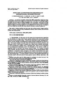
The run-time for the algorithm using different numbers of features for the particles can be seen in Fig. 11. 5 Parallelization Since simulations of this kind are time consuming even with fast algorithms, the code is implemented to run on cheap high-end shared memory workstations. The appropriate method for parallelization on this kind of machines is the use of Threads. 5.1 Threads Threads are a powerful tool for parallelization on appropriate computers designed for symmetric multiprocessor (SMP) architectures.4 This architecture has some striking features. All processors are physically sharing the same memory and have a single address space. The processors do not communicate by sending messages across a network. They exchange, or rather share information, by writing to and reading from memory. A thread of control, or more simply a thread, is an independent sequence of execution of program code inside a UNIX process. All threads share the memory of the 4
This kind of architecture is typical for “low-end”systems. Other systems have NUMA (Non-Uniform Memory Access), as used for example in the Cray T3E.
42
Average time (µs)
3.0 2.5 2.0 1.5 1.0 0.5 0
0
50
100 150 200 Number of edges
250
300
Fig. 11. Here the time needed for one call to the closest feature algorithm is shown. A Sun with a 200 Mhz Ultra2 processor was used. The slight increase for larger number of corners is due to the fact that more changes of the closest feature occur during the simulation (up to 100 times)
same process. The threads within a process are scheduled and executed independently in the same way as a normal UNIX processes. On multiprocessors, different threads may be executed on different processors [10,11]. One can imagine a program as a string of commands. The commands are executed one by one using one special unit. Using threads, one has two or more of such units, which work simultaneously. Two threads of a single program have the same program and data, but different memory for local variables and different instruction counters. A program starts with the main process. Then the programmer can create threads, which start to execute a given function with given data. Then, inside of a thread, one can of course call other functions, allocate memory, etc. like in a normal C-program. If shared resources such as variables can be modified, they have to be protected by a mutual exclusion or mutex for short. If one thread T1 has exclusive access to data, no other thread T2 can simultaneously access the same data. The most important thing for efficient programs is the organization of the data structures. According to the algorithms used one has three fundamental structures. One structure is for the representation of the particles. Here variables like position, velocity and shape are stored; also there is a mutex for protect the particle’s information. These structures are organized in a linked list. The second structure contains the bounding boxes. There are two linked lists, one for the X-axis, one for the Y -axis. The third type of structure represents a collision. This structure is for both bounding box collision and particle collision. If a collision for particle i and j (i < j) is found one keeps the structure for this collision in a small linked list, appended to the structure for particle i. So searching for a collision is much faster than in a long global list.
For the bounding-box algorithm explained in section 3, parallelization using threads can be performed in the following way. For the sake of simplicity, the code is subdivided into two threads, one for each axis. Since the information on each collision can be changed by both threads, the particle’s mutex is necessary to guarantee the integrity of the data. However, most of the time, the two threads do not have to wait. The result is an actual list of possible particle-particle collisions. To calculate the distance using the closest feature algorithm the threads have to read only from the structures of both particles, which are not changed in this step. The information is written to the structure of the collision, but by the program design it is guaranteed that no other thread reads information from there. So we do not need any mutex, both threads are completely independent. When both threads are finished, the information about which particles are colliding is stored in the collision structures. In the next step the force from each collision has to be determined. Therefore the overlap area for each particle pair is calculated. For these calculations one needs only information stored in the structure of the collision. Again, the list of all particles is split and each thread works on the according collisions. Information needed for the calculation of the force is not changed in this step, reading information does not require any mutex. But to sum up the total force for each particle is dangerous. It is possible that another thread is also working on a collision the particle is involved in. Hence the summation of the forces has to be protected with the particle’s mutex. However, since this event is unlikely one does not lose much time. When a Gear predictor-corrector method is used for solving the differential equations [3, 12] one needs a predictor and a corrector step. The first predicts position and velocity for the particles. Then one has to calculate the forces and the second step can correct position and velocity. Both predictor and corrector only read and write information inside a particle’s structure. So there is no Thread #1
t
Thread #2
Predictor
Synchronization
Predictor
Bounding-box X-axes
Mutex
Bounding-box Y-axes
Closest-feature algorithm Force calculation Corrector
Fig. 12. Basic structure of the algorithm for two threads. The combination of the incremental sort-and-update algorithm and closes-feature algorithm is shown, necessary uses of mutex variables are given
43
need to protect the data by a mutex. Hence the list of particles is splitted and calculated by threads. The outline of the parallel version of the algorithms can be seen in Fig. 12. Using the parallel version of the program on two processors gives an speedup of about 1.9 to 1.95 in contrast to the serial code. These values have been measured under working conditions, the computer doing this simulation was also working as file server.
References
1. John M. Ting, Jeffrey D. Rowell, and Larray Meachum, Influence of particle shape on the strengh of ellipseshaped granular assemblages. In John R. Williams, editor, Proceedings on the 2nd Interantional Conference on Discrete Element Methods (DEM), pages 215–225, Cambridge, Mass, 1993. IESL Publ. 2. Alexander V. Potapov and Charles S. Campbell, A fast model for the simulation of non-round particles. Granular Matter, 1/1:9–14, 1998 3. M. P. Allen and D. J. Tildesly, Computer Simulation of 6 Liquids. Clarendon, Oxford, 1987 Conclusion 4. A. Schinner, Numerische Simulationen f¨ ur granulare Medien. Master’s thesis, University of Regensburg, 1995 Different methods for speeding up a discrete element method have been shown. The incremental sort-and-update 5. D. Baraff, Rigid body simulation. In Course 60, An introduction to Physically Based Modelling, ACM Siggraph, algorithm is an improvement over Verlet tables and neighpages H1–H68, 1993 borhood lists. The algorithm is suitable for all kinds of 6. Sedgewick, Algorithmen. Addison-Wesley, 1992 interactions with finite range. The closest-feature algo7. Hans-Georg Matuttis. private communication rithm calculates the distance of two polygons in constant 8. M. C. Lin and D. Manocha, Interference detection betime based on a good guess from the last step, so that tween curved objects for computer animation. Models and Techniques in Computer Animation, pages 43–57, 1993 the collision detection is not longer the bottleneck for the 9. M. C. Lin, Efficient Collision Detection for Animation and simulation of polygonal particles. Both algorithms can be Robotics. PhD thesis, University of Californa at Berkeley, parallelized using threads, so common multiprocessor work1993 stations can perform highly sophisticated simulations of 10. S. Kleinman, D. Shah, and B. Smaalders, Programming granular matter [13]. with Threads. SunSoft Press A Prentice Hall Title, 1996 11. B. Nichols, D. Buttla, and J. P. Farrell, Pthreads Programming. O’Reilly & Associates, Inc., 1997 12. C. William Gear, Numerical initial value problems in ordinary differential equations. Prentice-Hall, Englewood Cliffs, NJ, 1971 13. Alexander Schinner, Movies on granular matter. http://itp.nat.uni-magdeburg.de/∼schinner/granular/ movies.html