We propose a formal verification approach which smoothly integrates with a component based sys- tem-level design methodology. Once a timed Petri Net model ...
Formal Verification in a Component-based Reuse Methodology Daniel Karlsson, Petru Eles, Zebo Peng IDA, Linköpings universitet, 581 83 Linköping, Sweden
{danka, petel, zebpe}@ida.liu.se ABSTRACT There is an important trend towards design processes based on the reuse of predesigned components. We propose a formal verification approach which smoothly integrates with a component based system-level design methodology. Once a timed Petri Net model corresponding to the interface logic has been produced the correctness of the system can be formally verified. The verification is based on the interface properties of the connected components and on abstract models of their functionality, without assuming any knowledge regarding their implementation. We have both developed the theoretical framework underlying the methodology and implemented an experimental environment using model checking techniques.
Categories and Subject Descriptors C.0 [Computer Systems Organization]: General - Systems specification methodology; B.7.2 [Integrated Circuits]: Design Aids Verification; I.6.4 [Simulation and Modeling]: Model Validation and Analysis; J.6 [Computer-Aided Engineering]: Computeraided design (CAD)
General Terms Performance, Design, Verification
Keywords Formal Verification, IP, Reuse, Model Checking, Timed Petri-Nets
1. INTRODUCTION One of the important current trends is towards a design process based on the reuse of predesigned blocks [1]. Such blocks can be both hardware and software components. With such a design process, also called ”interface based design” [2], the focus is on the interaction of components and, in particular, on interfaces, protocols and glue logics which interconnect independent blocks. Once a design alternative has been produced, one crucial aspect is the verification of interfaces and of the global system functionality. There are several aspects which make this task very difficult. One is the complexity of the systems, which makes simulation based techniques very time consuming. On the other hand, formal verification of such systems suffers from state explosion. Another problem is the lack of information about the internals of predesigned blocks. However, it can often be assumed that the design of each individual component has been verified and can be supposed to be correct [3]. What remains to be verified is the interface logic (hardware or software). Such an approach can handle both the complexity aspects (by a divide and conquer strategy) and the lack of information concerning the internals of predefined components. Although several approaches have been proposed tackling aspects of component based design, there exists, to our knowledge, no work concerning the integration of such a design process with formal verification. As a main contribution, in this paper we propose a formal verification approach which smoothly integrates with a component based system-level design methodology for embedded systems. The approach is based on a timed Petri Net notation. Once the model corresponding to the interface logic has been produced, the Permission to make digital or hard copies of all or part of this work for personal or classroom use is granted without fee provided that copies are not made or distributed for profit or commercial advantage and that copies bear this notice and the full citation on the first page. To copy otherwise, or republish, to post on servers or to redistribute to lists, requires prior specific permission and/or a fee. ISSS’02, October 2-4, 2002, Kyoto, Japan. Copyright 2002 ACM 1-58113-562-9/02/0010...$5.00.
correctness of the system can be formally verified. The verification is based on the interface properties of the interconnected components and on abstract models of their functionality, without assuming any knowledge regarding their implementation. We have developed both the theoretical framework underlying the methodology and implemented an experimental environment for its application, using model checking techniques. Our approach represents a contribution towards increasing both design and verification efficiency in the context of a methodology based on component reuse. Section 2 of the paper introduces the design representation, followed by a preliminary discussion in Section 3. The verification technique is presented in Section 4 where we both develop the theoretical framework and discuss some examples. Experiments are presented in Section 5 and the conclusions are given in Section 6.
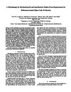
2. PRES+: THE DESIGN REPRESENTATION In order to support our modeling approach, we have defined a Petri Net based representation called PRES+ [4]. The following extensions to classical Petri Nets are the most important in the context of this paper (see Figure 1): 1. A token k has values and timestamps, k = 〈 v, r〉 where v is the value and r is the timestamp. 2. A transition has a function and a time delay interval associated to it. When a transition fires, the value of the new token is computed by the function, using the values of the tokens which enabled the transition as arguments. The timestamp is increased by an arbitrary value from the time delay interval. In Figure 1, the functions are marked on the outgoing edges from the transitions. 3. The PRES+ net is forced to be safe, i.e. one place can at most accommodate one token. A token in an output place of a transition disables the transition. 4. The transitions may have guards. A transition can only be enabled if the value of its guard is true (see transitions t 4 and t 5 ). 5. The preset °t (postset t° ) of a transition t is the set of all places from which there are arcs to (from) transition t . Similar definitions can be formulated for the preset (postset) of places. In Figure 1, °t 4 = { p4, p5 } and t 4 ° = { p6 } . We will now define three concepts which are critical to our methodology, in the context of the PRES+ notation. Definition 1. Component. A component is a subgraph of the graph of the whole system Γ = P ∪ T ( P is the set of places and T is the set of transitions) such that: 1. Two components C 1, C 2 ⊆ Γ , C 1 ≠ C 2 may only overlap with their ports (Definition 2), where C 1 ∩ C 2 = Pconnect , Pconnect = { p ∈ P ( p° ⊆ C 2 ∧ °p ⊆ C 1 ) ∨ ( p° ⊆ C 1 ∧ °p ⊆ C 2 ) } . 2. The pre- and postsets ( °t and t° ) of all transitions t ∈ C must be entirely contained within the component C , °t, t° ⊆ C . Definition 2. Port. A place p is an out-port of component C if ( p° ∩ C = ∅ ) ∧ ( °p ⊆ C ) or an in-port of C if ( °p ∩ C = ∅ ) ∧ ( p° ⊆ C ) . p is a port of C if it is either an in-port or an out-port of C . Definition 3. Interface. An interface of component C is a set of ports I = { p1, p2, … } where pi ∈ C . [3, 4] t4
x+5 x p1
t1 [2, 5]
in-port
p2
x x
x
x p3
t2 t3
[3, 7]
p4
x y
[2, 5]
x-5 p5
x
xy
[x>2y]
p6
out-ports t [3, 4] 5 x [x