LORIA - UHP Nancy 1. Campus scientifique, BP 239. 54506 VandÅuvre-l`es-Nancy, France. {aron ..... [1] A. Comport, E. Marchand, and F. Chaumette. A real- ...
Handling uncertain sensor data in vision-based camera tracking Micha¨el Aron1 Gilles Simon2 Marie-Odile Berger1 1 2 LORIA - INRIA Lorraine, LORIA - UHP Nancy 1 Campus scientifique, BP 239 54506 Vandœuvre-l`es-Nancy, France {aron,gsimon,berger}@loria.fr Abstract A hybrid approach for real-time markerless tracking is presented. Robust and accurate tracking is obtained from the coupling of camera and inertial sensor data. Unlike previous approaches, we use sensor information only when the image-based system fails to track the camera. In addition, sensor errors are measured and taken into account at each step of our algorithm. Finally, we address the camera/sensor synchronization problem and propose a method to resynchronize these two devices online. We demonstrate our method in two example sequences that illustrate the behavior and benefits of the new tracking method.
1. Introduction One of the key technological challenges for augmented reality (AR) is to be able to track the user’s viewing position and orientation in real-time, in order to maintain accurate alignment between real and computer-generated objects. Our purpose is to perform this task in unprepared environments, which proscribes marker-based methods as well as mechanic and magnetic sensor devices. However, camera tracking in unprepared scenes is not an easy task and it is difficult to obtain a system that is sufficiently accurate, fast and robust for effective AR applications. Inertial sensors provide orientation data in unprepared environments, but their accuracy is still insufficient for satisfying alignment. Global Positioning System (GPS) provides positioning, but again accuracy is not sufficient, especially when the area to cover is small. By contrast, visionbased methods are generally more accurate as they depend on features that are directly extracted from the images to be augmented. However, markerless systems generally suffer from high computation costs and are often suitable for post-production only. Some systems have been proposed recently that perform markerless tracking in real-time, but a
model of the scene is generally needed [1][8], or a learning stage is required [4]. In [10], we proposed a less constraining approach adapted to multi-planar scenes: planar surfaces were designed interactively by the user and tracked automatically from frame to frame, providing camera pose in real-time. However, this method was based on key-points matching between consecutive images, which is not robust against abrupt motions. Hybrid systems attempt to compensate for the shortcomings of each technology by using multiple measurements to produce robust results. Extended or adapted Kalman filters have been widely used for multi-sensor data fusion [13][14][3]. However, such filters require good measurement models which are difficult to obtain in AR where the user is generally free of his motions. Another apporach consists of using sensors as prediction devices to guide image feature detection: in [11], a magnetic sensor is used to help landmark search, whereas in [7] and [6], a gyroscope is used to predict the 2d position of edges corresponding to a wireframe model of the scene. In [7], the sensor is also used to provide an estimate of motion blur for each feature and improve feature detection. Our approach is close to these works, in that sense that we use an inertial sensor to help finding image features. However, our method profits by the following contributions: 1. to reduce the computational cost, the inertial device is not used systematically, but only when needed (generally after a large rotation occured), 2. sensor errors are measured and taken into account at each step of the algorithm. For example, propagation of these errors enables us to obtain refined research areas of image features, that are much more relevant than arbitrary rectangles; 3. sensor data are not only used to predict the position of the features, but also to refine the matching process and obtain a higher number of correct matches, 4. the synchronization problem is treated, whereas rarely mentioned in previous works: we show that the syn-
Proceedings of the Third IEEE and ACM International Symposium on Mixed and Augmented Reality (ISMAR 2004) 0-7695-2191-6/04 $20.00 © 2004 IEEE
chronization delay between image and sensor acquisitions is varying over time, which requires to perform real-time resynchronizations during the tracking process. We propose a reliable method for this purpose; Large translations are not considered in this paper, though it would not be difficult to integrate positioning sensor data in our system if that information were available. However, abrupt motions often come from head or hand rotations, depending on where the camera is mounted. The markerless tracking system we presented in [10] is used as a basis of our hybrid algorithm. This system has the advantage of requiring neither landmark in the scene nor model of that scene to recover camera poses. Section 2 presents the inertial sensor and error measurements we obtained on this device. Section 3 evokes the sensor-camera synchronization problem, and presents the sensor-camera calibration method. The vision-based tracking system is briefly described in section 4, and the hybrid method we propose is detailed in section 5. Finally, experimental results are presented and we conclude.
(covariances between axes are negligeable). This matrix will be used later for error prediction in feature matching. AMD ON Axis σ(deg) X 0.57 Y 0.23 Z 1.17
AMD OFF Axis σ(deg) X 0.63 Y 0.22 Z 1.36
Table 1. RMS accuracy of the sensor according as AMD option is used or not.
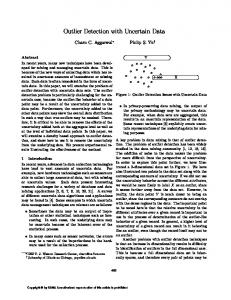
2. Sensor accuracy The inertial device we used for experiment is a threedegree of freedom orientation tracker produced by Xsens (model MT9-B). A proprietary sensor fusion algorithm integrates measurements of gravity (accelerometers) and magnetic north (magnetometers) to compensate for otherwise unlimited increasing errors from the integration of rate of turn data (gyroscopes). To assess the accuracy of this sensor in practical environments, we fixed it at a distance of 20 cm from a camera on, and put the camera on a digitally-controlled pan / tilt unit. Several rotations were applied to each axis of the sensor. Two sets of tests were performed, one with AMD option set to on, and another with this option set to off. AMD (Adapt to Magnetic Disturbances) is a proprietary correction algorithm delivered by Xsens to decrease the effect of ferromagnetic materials on the accuracy of the orientation estimation (ferrous material disturb the homogeneous earth magnetic field used as a reference by the MT9). The RMS (root-mean-square) error we obtained for each axis is given in table 1 (axes are represented in Fig. 1). One can see that accuracy differs from one axis to another: Y axis gives more accurate results than X axis, which gives more accurate results than Z axis. These results provide two covariance matrices (according as AMD option is used or not) of the Euler angles αA , βA , γA of the sensor-measured rotation: 2 0 σZ 0 0 ΣA = 0 σY2 2 0 0 σX
Figure 1. MT9 with body-fixed coordinate system overlay.
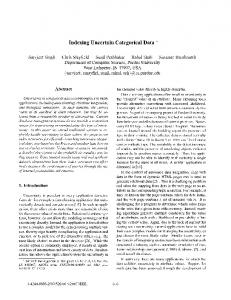
3. Camera-sensor coordination 3.1. Synchronization In order to make sensor data coincide with camera data, we tried to implement a synchronization procedure based on abrupt motions detection. Several abrupt motion where performed in a same shoot, and abrupt changes in rotation angles were matched to abrupt changes in image intensities distribution (a criterion is proposed in [9]). Unfortunately, we found that is was not possible to synchronize these two devices, as the synchronization delay was not constant over time. For example, Fig. 2 shows some results we obtained in the same shoot: three successive abrupt motions provided three different delay values (1-5-2).
3.2. Hand-eye calibration When the inertial sensor is rigidly attached to the camera, camera rotations can be deduced from sensor rotations by using the following equation: AX = XB,
Proceedings of the Third IEEE and ACM International Symposium on Mixed and Augmented Reality (ISMAR 2004) 0-7695-2191-6/04 $20.00 © 2004 IEEE
(1)
1.2e+07 Prager criterion Rescaled rotation angle 1e+07
8e+06
6e+06
Figure 3. Hand-eye transformation. 4e+06
mj using the simple equation
2e+06
m � j = Hp m j ,
0 90
100
110
120
130
140
150
160
170
180
190
200
210
220
230
240
# image
Figure 2. Synchronization delay between inertial sensor and camera is not constant over time.
where A denotes the sensor rotation matrix, B the camera rotation matrix and X the rotational part of the transformation between the two coordinate systems (see Fig. 3). The procedure that consists of computing matrix X is generally called “hand-eye calibration”: A and B are measured from different orientations of the camera-sensor device (three at minimum), and X is obtained as the solution of the generated set of equations. Several methods have been proposed to solve this set of equations. Although iterative resolution was suggested to reduce the influence of noise in measurements [12], we obtained equivalent results by solving this system linearly. This calibration step also provides a covariance matrix ΣX of the Euler angles αX , βX , γX of matrix X, whose computation is given in appendix. In our implementation, camera matrices were obtained from images of a calibration target. The inertial sensor was fixed to the camera so that the less accurate axis Z was approximately aligned with the optical axis of the camera: this made impossible rotations around this axis, as camera rolls are not possible when the camera is mounted on a tripod.
4. Vision-based tracking A real-time camera tracking system was presented in [10]: camera positions were computed from key-point correspondences belonging on planar surfaces. This section briefly describes how this pure vision-based system worked. Let us consider a plane Πp in the scene and two views V 1 and V 2 of that scene; let mj and m� j be the projections in homogeneous coordinates of the same 3d point Mj ∈ Πp , in V 1 and (respectively) V 2 . Then m� j can be obtained from
(2) 1
where Hp is the planar homography between V and V 2 , corresponding to plane Πp and given by [5]: Hp = K(A − aπpt )K −1 , where πp is the equation vector of Πp expressed in coordinate system V 1 , A and a denote the relative rotation and translation of the camera between V1 and V2 , and K is the intrinsic parameters matrix. Therefore, if L planes are known and Np points are matched on each plane Πp , then A and a can be taken as the parameters that minimize the cost function c(A, a) =
Np L � � p=1 j=1
p
dist2 (m� j , Hp mpj ),
where dist is the Euclidean distance between two pixels. This method has proven relevant in several augmented reality applications. It is robust against false correspondences as the point-to-point constraint provided by equation (2) enables to use a RANSAC algorithm [2] to discard outliers. However, key-point correspondences can not be obtained from distant images. Unfortunately, abrupt motions may occur in augmented reality scenarios, especially when the user turns his head quickly. Moreover, as the process is incremental (pose in view V i is computed from pose in view V i−1 ), matching failure means that the process has to be stopped. In our implementation, tracking could start again if the user succeeded in coming back to a position close to the position just before the system failed (so that key-points could be matched again), but this was not very convenient. Using a sensor in a hybrid process will allow us to handle this drawback.
5. Hybrid tracking Section 2 showed that about 1o RMS accuracy was expected from inertial sensors. Although adequate for interactive applications in virtual reality, this accuracy is inadequate for AR tracking. An example was given in [15], where
Proceedings of the Third IEEE and ACM International Symposium on Mixed and Augmented Reality (ISMAR 2004) 0-7695-2191-6/04 $20.00 © 2004 IEEE
the authors computed alignment errors for different orientation errors (a classical CCD video camera with typical focal length was used) . They showed that each degree of orientation angle error was resulting in about 11-pixels of alignment error in the image plane. Moreover, these errors accumulates over time, which means that periodic measurements from other sensors must provide absolute pose data. By contrast, our vision-based method provides accurate results, except for rapid motions where the process fails to match features. Our strategy thus consists in not using sensor data as long as the vision-based system succeeds in tracking features and computing the pose. This enables us to reduce the computational costs. An important point is that we are able to check if the vision-based system is going to fail. When this happens, and only then, the inertial sensor is used in that way:
1. Position prediction of research windows (Fig. 4(b)): when a large motion occurs, key-point m� corresponding to key-point m is generally outside the research window W: that is the reason why the vision-based tracking system generally stops. When inertial sensor data are available, these data can be used to predict the position of W in image i: if B is denoting the camera relative rotation deduced from sensor data as seen in section 3, a predicted homography Hs can be obtained as: Hs = KBK −1 , and research window W can be centered at position Hs m. 2. Refined research regions (Fig. 4(c)): fixed size rectangles are commonly used as research regions for key-point correspondences. However, when key-points transformations are predictable and a covariance matrix can be obtained on these predictions, refined research regions can be obtained. Indeed, confidence ellipses can be obtained from equation
• camera rotations are temporary computed from sensor data (approximative pose is still better than unknown pose), • key-points matching is attempted, using information provided by sensor data,
X t Σ−1 m� X ≤ 9.21,
• once enough key-points are matched, the vision-based system starts again.
where Σm� is the covariance matrix of the 2d coordinates of m� , and value 9.21 is the 99% confidence limit for a two degrees of freedom chi-square. As key-point m� is predicted at position p(m) = Hs m = KBK −1 m = KX t AXK −1 m, Σm� is linearly approximed by:
5.1. Sensor-guided matching This section describes how sensor data can be used to help the matching process after a large camera rotation occured. Classical key-points matching is working as follows (see figure 4(a)): 1. for each key-point m in image i − 1, a research window W is set around that point, 2. for each key-point {m�k }1≤k≤M in image i inside W, a cross-correlation score is computed between m and m�k as � � � � � � � c(m, m ) = k
i
j
(I(u + i, v + j) − I)(I (u + i, v + j) − I )
�
σ2 σ2 I I�
,
where (i, j) is varying inside a rectangle (the correlation window) centered at the origin (I and I � are pixel intensities in both images). 3. m�l is matched to m if c(m, m�l ) = max({c(m, m�k )}1≤k≤M ) and c(m, m�l ) > t (typically t = 0.8). When sensor data are available, these data can be used profitably at three different levels of this algorithm:
(3)
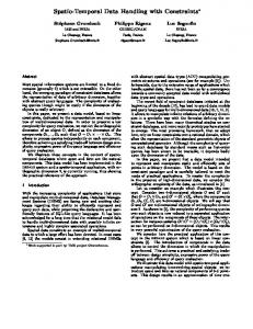
t t Σm� = JX/m ΣX JX/m + JA/m ΣA JA/m , � ∂p ∂p ∂p where JA/m = and JX/m = ∂αA ∂βA ∂γA � ∂p ∂p ∂p (the intrinsic parameters are sup∂αX ∂βX ∂γX posed exact). Figure 5 shows examples of ellipses we got at regular intervals in a 320 × 240 image, with ΣA corresponding to the left data of table 1. One can see that the research regions are much more relevant than arbitrary rectangles, as they now depend on the predicted rotation and its uncertainty, and also on the 2d position of the key-points.
3. Rectified correlation windows (Fig. 4(d)): in standard matching, cross-correlation scores are computed inside rectangle windows: this supposes that the windows do not deform too much between consecutive frames. Unfortunately, when large rotations occur, this assumption is not valid anymore. However, the sensor predicted homography tells us how the windows are deformed, and a new correlation score c2 (m, m� ) can be obtained by replacing I � (u� + i, v � + j) in equation (3) by I � (Hs (u + i v + j 1)t ). This is equivalent to rectify image i − 1 according to the predicted homography Hs , and match the resulting image to image i
Proceedings of the Third IEEE and ACM International Symposium on Mixed and Augmented Reality (ISMAR 2004) 0-7695-2191-6/04 $20.00 © 2004 IEEE
m’3 m3
m2
m’3 m3
m2
m’2 Research window
m4
m1
m’2 m4 m’1
m1
m’1
H
I Correlation window
Image 2
Image 1
Image 2
Image 1
(a)
(b)
m’3 m3
m2
m’3 m3
m2
m’2 m4
m’2 m4
m’1
m1
m’1
m1
H
H Image 2
Image 1
(c)
Image 2
Image 1
(d)
Figure 4. Key-points matching using sensor data. (a) Vision-based classical matching. (b) Position of the corresponding key-point is predicted using sensor data. (c) An elliptic research region is obtained by propagating sensor error. (d) The correlation window is transformed using the predicted homography.
5.2. Sensor integration
Figure 5. Example of research regions obtained by propagating sensor errors in a 320x240 image.
(see Fig. 6). Figure 7 shows an histogram of the correlation scores we obtained for correspondences on the pair of images given in figure 6 (the correlation threshold t was set to 0.7). Correlation scores are higher and correct correspondences in larger number (91 against 79) when rectified windows are used rather than rectangle windows.
To implement our strategy, we have to define a criterion that allows us to decide when to switch between the visionbased system and the sensor-based system, and conversely. As we already mentioned, equation (2) provides a point-to-point constraint that allows us to discard false p matches: correspondences for which dist(m� j , Hp mpj ) is smaller than an arbitrary threshold (1.25 pixels in our implementation) are discarded. Therefore, a criterion we can use to check if the vision-based system failed is the number of correct correspondences #inliers that have been kept during RANSAC selection. When #inliers becomes lower than a given threshold tin (tin = 10 for example), the vision-based system is considered as unable to continue, and the inertial sensor is used for matching, until #inliers passes above the threshold again. One crucial problem that has to be solved in this method concerns the synchronization delay between sensor and camera. As we mentioned in section 3, this delay is not constant over time, which means that we have to resynchronize the two devices online. To do this, we take into account the fact that sensor data
Proceedings of the Third IEEE and ACM International Symposium on Mixed and Augmented Reality (ISMAR 2004) 0-7695-2191-6/04 $20.00 © 2004 IEEE
45 rectangle correlation windows rectified correlation windows 40
35
#correspondences
30
25
20
15
10
5
0 0.6
(a)
(b)
(c) Figure 6. Image rectification according to the predicted homography Hs : image (c) is the rectified image (a), that must be matched to image (b).
are always available before image data. Indeed, the time needed to capture a video frame from the camera and transfer this frame from video hardware to tracking system is large compared to the time needed to sample information from the inertial sensor. Then, if sensor rotations are stored in a buffer, this buffer must contain all the rotations that should be used for matching and pose computation once the vision-based system has stopped. For example, figure 8 shows #inliers for an illustrative sequence. This number decreases drastically in frame 11, which makes the visionbased system stop. However, the corresponding sensor homography H11 was bufferized while frame 9 was treated. Therefore, after a matching failure has been detected, sensor-predicted homographies are extracted from
0.7
0.8 cross correlation score
0.9
1
Figure 7. Correlation scores obtained for rectangle and rectified correlation windows.
the buffer, and the matching process is tried using the accumulated homography. Accumulating homographies is necessary as a rapid rotation may last more than one acquisition cycle, or several rotations may follow one another before the matching process succeeds. However, we still have to know which is the first homography that has to be extracted from the buffer. This homography must exactly correspond to the frame that made the vision-based system stop. To get it, another threshold could be introduced in order to detect abrupt changes in sensor rotation angle. Unfortunately, it is not easy to choose a value for this threshold as image disconnections depend on the amplitude of the rotation, but also on the focal length of the camera and the 2d coordinates of the key-points. For that reason, we prefer to use a criterion that is directly linked to image features. Let us suppose that the vision-based system stopped at frame s and let S be the set of key-points in frame s − 1 that were correctly matched with key-points in frame s − 2. The idea is to transfer points of S with each homography in the buffer, and choose the homography that potentially makes the matching fail, that is for which less than tin transfered points are inside the vision-based research windows. For example in figure 8, when a matching failure is detected in frame 11, inlier keypoints of frame 10 are transfered using each bufferized homography. For homographies H8 , H9 and H10 , enough keypoints are transfered inside the vision-based research windows, whereas for homography H11 the predicted number of inliers decreases dramatically. This sensor-predicted number of inliers is a much more discriminant criterion than the rotation angle, and enabled us to obtain perfect synchronization in most situations.
6. Experimental results Our hybrid system has first been experimented on a miniature indoor scene (see Fig. 6). To compare pure visionbased tracking with hybrid tracking, the sequence was shot using sensor information, but retreated offline using image
Proceedings of the Third IEEE and ACM International Symposium on Mixed and Augmented Reality (ISMAR 2004) 0-7695-2191-6/04 $20.00 © 2004 IEEE
# computed inliers
# sensor−predicted inliers
Sensor homographies
H3
H4
H5
H6
H7
H8
H9
H10 H11 H12 H13 H13 H14 Buffer
1
2
3
4
5
6
7
8
9
10
11
12
13
#frame
Figure 8. Online synchronization between camera and sensor. information only. Figure 9 shows the number of inlier correspondences and the tracking-less periods we obtained in both cases. In the vision-based sequence, large tracking-less periods are observed, that correspond to rapid camera rotations. Fortunately in that sequence, the user often restored the scene to the center of the view, which made possible tracking recovery. In the hybrid sequence, tracking-less periods are much shorter. Figure 10 zooms at two sensor-guided matching periods and shows the sensor angles and the predicted numbers of inliers that were bufferized at breakdown points. These graphics confirm that the image-based criterion is more discriminant in breakpoint detection than the sensor angle criterion. Figure 10(b) also shows an example where sensor homographies were cumulated during a large period before matching succeeded, as two consecutive rapid rotations were applied. Two videos are available on our web site1 that show these sequences completely (mini scene without sensor.avi and mini scene with sensor.avi). Other experiments were conduced within a project of ecommerce: the aim was to aid the furniture retail customer to visualize a furnished interior by allowing the seamless integration of virtual furniture models into customer’s environment. A sequence was shot in the basement of our laboratory and some furnishings were added online. Figure 11 shows examples of compositions we obtained before and after rapid rotations were applied to the camera. Correspondences obtained from sensor-guided matching are also shown in this figure. Outlier correspondences are drawn in black, inlier correspondences in white. The whole videos
are available on our web site (real scene matches.avi, real scene augmented.avi).
7. Conclusion We presented a hybrid approach for real-time markerless tracking in multi-planar environments. Inertial sensor data and image data were combined in order to provide robust and accurate tracking. Unlike previous approaches, we use sensor information only when the pure vision-based system fails to track the camera. In addition, sensor errors are measured and taken into account in the key-points matching process. Finally, we address the camera/sensor synchronization problem and propose a method to resynchronize these two devices online. Our method has proven relevant in effective AR applications. However, although inertial sensor robustness allows to maintain tracking during long sequences, the process is still incremental and may progressively diverge because of successive approximations. Markers or natural features of the scene could be used to detect system divergences and reinitialize the tracking when necessary.
Acknowledgments This research is being supported with EC-grant IST2000-28707 (ARIS project).
Appendix: error propagation in hand-eye calibration Hand-eye matrix X is solution of the set of equations
1
http://webloria.loria.fr/equipes/isa/movies/ismar04.html
Ai X = XBi ,
Proceedings of the Third IEEE and ACM International Symposium on Mixed and Augmented Reality (ISMAR 2004) 0-7695-2191-6/04 $20.00 © 2004 IEEE
(4)
#inliers tracking stopped 200
150
100
50
0
0
(a)
10
20
30
40
50
60
80
70
90
100 110 #image
120
130
140
150
160
170
180
190
200
210
200
210
#inliers sensor-guided matching 200
150
100
50
0
0
(b)
10
20
30
40
50
60
80
70
90
100 110 #image
120
130
140
150
160
170
180
190
Figure 9. Vision-based tracking (a) against hybrid tracking (b).
#inliers sensor-guided matching sensor rotation angle x 5 (deg) #predicted inliers
200
150
150
100
100
50
50
0 160
162
164
166
168
170 #image
172
174
176
178
#inliers sensor-guided matching sensor rotation angle x 5 (deg) #predicted inliers
200
180
0 176
178
180
(a)
182
184 #image
186
188
190
192
(b)
Figure 10. Examples of camera/sensor synchronization in the miniature scene sequence. where (Ai , Bi ) are n sensor/camera rotation pairs. Our aim is to compute a covariance matrix ΣX of the Euler angles αX , βX , γX of matrix X, considering that camera rotations Bi are certain but sensor rotations Ai uncertain. Equations (4) can be written as f (x, a) = 0, where x is a vector of size 3 containing the Euler angles of rotation X, a is a vector of size 3n containing the Euler angles of rota-
tions Ai , and 0 is a 9n null vector. A first order approximation of f (x, a) gives: ∂f ∂f (x, a) (x − x) + (x, a) (a − a) = 0, ∂x ∂a where a and x are the estimated values of a and x. This leads to: CΣX C t = D [ΣA ] Dt , f (x, a) +
Proceedings of the Third IEEE and ACM International Symposium on Mixed and Augmented Reality (ISMAR 2004) 0-7695-2191-6/04 $20.00 © 2004 IEEE
Figure 11. Some results obtained in an indoor sequence. ∂f where C = ∂f ∂x (x, a), D = � ∂a (x, a) and [ΣA ] is the ΣA 0 ΣA 3n × 3n matrix . Therefore, ΣX can be ex... 0
pressed as:
ΣA
ΣX = (C t C)−1 C t D [ΣA ] Dt C(C t C)−1 .
References [1] A. Comport, E. Marchand, and F. Chaumette. A real-time tracker for markerless augmented reality. In Proceedings of the Second IEEE and ACM International Symposium on Mixed and Augmented Reality, Tokyo, pages 36–45, June 2003. [2] M. A. Fischler and R. C. Bolles. Random Sample Consensus: A Paradigm for Model Fitting with Applications to Image Analysis and Automated Cartography. Communications of the ACM, 24(6):381–395, 1981. [3] E. Foxlin and L. Naimark. A wearable vision-inertial selftracker. In IEEE Virtual Reality 2003 (VR2003), Los Angeles, CA, Mar. 2003. [4] Y. Genc, S. Riedel, F. Souvannavong, C. Akinlar, and N. Navab. Marker-less tracking for ar: A learning-based approach. In Proceedings of the First IEEE and ACM International Symposium on Mixed and Augmented Reality, Darmstadt, Germany, pages 295–304, Sept. 2002. [5] R. I. Hartley and A. Zisserman. Multiple View Geometry in Computer Vision. Cambridge University Press, ISBN: 0521623049, 2000.
[6] B. Jiang, S. You, and U. Neumann. A robust hybrid tracking system for outdoor augmented reality. In IEEE Virtual Reality 2004, Chicago, pages 3–10, Mar. 2004. [7] G. Klein and T. Drummond. Tightly Integrated Sensor Fusion for Robust Vision Tracking. In Proceedings of the British Machine Vision Conference, BMVC 02, Cardiff, pages 787–796, Sept. 2002. [8] V. Lepetit, L. Vachetti, D. Thalmann, and P. Fua. Fully Automated and Stable Registration for Augmented Reality Applications. In Proceedings of the Second IEEE and ACM International Symposium on Mixed and Augmented Reality, Tokyo, pages 93–101, June 2003. [9] R. W. Prager, A. H. Gee, and L. Berman. Stradx: real-time acquisition and visualisation of freehand 3D ultrasound. report cued/f-infeng/tr 319, Cambridge University Department of Engineering, 1998. [10] G. Simon and M.-O. Berger. Reconstructing while registering: a novel approach for markerless augmented reality. In International Symposium on Mixed and Augmented Reality, Darmstadt (Germany), Sept. 2002. [11] A. State, G. Hirota, D. Chen, W. Garett, and M. Livingston. Superior Augmented Reality Registration by Integrating Landmark Tracking and Magnetic Tracking. In Computer Graphics (Proceedings Siggraph New Orleans), pages 429–438, 1996. [12] R. Y. Tsai and R. K. Lenz. A New technique for Fully Autonomous and Efficient 3D Robotics Hand/Eye Calibration. IEEE Transactions on Robotics and Automation, 5(3):345– 358, June 1989. [13] G. Welch and G. Bishop. Scaat: Incremental tracking with incomplete information. In ACM Computer Graphics, Los Angeles, CA, pages 333–344, Aug. 1997.
Proceedings of the Third IEEE and ACM International Symposium on Mixed and Augmented Reality (ISMAR 2004) 0-7695-2191-6/04 $20.00 © 2004 IEEE
[14] S. You and U. Neumann. Fusion of vision and gyro tracking for robust augmented reality registration. In Proc. IEEE Conference on Virtual Reality, pages 71–78, March 2001. [15] S. You, U. Neumann, and R. Azuma. Hybrid inertial and vision tracking for augmented reality registration. In Proceedings of IEEE VR ’99 (Houston, TX, 13-17), pages 260–267, 1999.
Proceedings of the Third IEEE and ACM International Symposium on Mixed and Augmented Reality (ISMAR 2004) 0-7695-2191-6/04 $20.00 © 2004 IEEE