The International Journal of Virtual Reality, 2007, 6(1):35-44
35
Impostors, Pseudo-instancing and Image Maps for GPU Crowd Rendering Erik Millán and Isaac Rudomín1 Abstract— Rendering large crowds of characters requires a great amount of computational power. To increase the efficiency for this render, we propose the use of the graphics processor, in combination of two different level-of-detail techniques: impostors, for characters with low detail, and pseudo-instancing, for characters with full detail. In addition, different approaches are used to increase the diversity in appearance for these characters, and a shadow mapping technique is integrated into the simulation. Keywords—Crowds, GPU.
level-of-detail
techniques,
impostors,
I. INTRODUCTION Large crowds of characters are not very common in virtual environments. One of the main reasons why this happens is that their render demands intensive processing resources. Similarly, videogames have been restricted to crowds of a few thousand characters. In a restricted environment, where a single processor must be used to manage every aspect of a videogame or a virtual environment, resources are usually drawn towards more critical and less demanding areas, making the use of crowds a non-affordable luxury for most applications. In order to overcome these limitations, several level-of-detail approaches can be used. The purpose of a level-of-detail technique is to reduce the detail of those objects on a virtual environment that are rendered to a small portion of the screen. In this way, distant characters use a lower detail, which is not noticeable by most users in terms of visual artifacts, but which is highly noticed in terms of speed. On the contrary, characters close to the camera will be more detailed, as this additional detail can be better appreciated. Programmability of current graphics processors provide with additional opportunities to harness their expanding processing capabilities and handle different stages of the rendering pipeline in ways not possible before. This article presents a technique to use such power to improve the efficiency in rendering large crowds of characters. Different levels of detail are used to enhance the rendering efficiency for such large crowds. Impostors are used as an efficient image-based approach to reduce the geometry of a character to a single polygon. For full-detailed characters, a pseudo-instancing technique for animated models reduces the time used to render Manuscript Received on November 12, 2006. This work was supported by the Instituto Tecnologico y de Estudios Superiores de Monterrey, Campus Estado de Mexico (ITESM-CEM) through project IVE. Isaac Rudomin is a professor in the department of Computer Science at ITESM-CEM, email:
[email protected]. Erik Millan is a doctoral student in the Computer Science Program at ITESM-CEM, email:
[email protected].
animated models. In addition, graphics hardware is used to generate additional diversity in the appearance of rendered characters, as well as to increase realism by adding shadows to the scene. II. RELATED WORK Due to its complexity, crowd rendering has been an extensively studied subject. Different methods have been used in order to reduce the overhead involved in rendering a large number of distinguishable characters. Attempts to reduce the detail of geometric models are extensive, existing many different possibilities. One of the first ideas on detail reduction is to use a small number of vertices from an initial surface and re-triangulate those vertices. This can be done by uniformly distributing a new set of vertices on a surface, and then remove original vertices one by one to obtain a smaller detail [1]. In another approach, Progressive Meshes [2], one vertex is removed iteratively over an existing surface, creating a hierarchical structure that enables to render such surface with an arbitrary number of vertices. The main problem with mesh reduction is the changing topology of the mesh. Different topologies must be computed for different levels of detail. Then, these topologies must be stored in memory as vertex indices, and either uploaded constantly or cached on the graphics memory, which increases the use of bandwidth or memory for these approaches. A better approach that eliminates connectivity-related problems are point-based rendering algorithms that replace low-detail geometry with a dense array of points [3] which can contain different attributes of the original model. Different techniques have been proposed to display large clouds of points as solid objects, such as Q-splats [4] or surfels [5], including information such as normal vectors, color or texture coordinates. There are some point-based rendering implementations for animated models [6, 7], where points query information from the polygonal model. Even when there are no connectivity problems for point-based rendering, the use of a variable number of vertices is still a problem in current graphics hardware. Geometry shaders on next generation hardware may privilege point-based techniques, as a single vertex will suffice to display an arbitrary number of point primitives. However, in current generation commodity hardware, this arbitrary number of primitives still presents a problem on efficiency. A very common approach for crowd rendering is the use of image-based rendering techniques. In these techniques, the geometry of a model is replaced by a very small set of textured polygons that look very similar to the original geometry. Aubel et al. [8] presented impostors as an image-based approach to display virtual objects. An impostor displays a character as a
The International Journal of Virtual Reality, 2007, 6(1):35-44
36
textured polygon, usually a square, which continuously faces toward the camera. The texture coordinates for this polygon will change according to the current viewing position of the camera and, for animated models, to the current animation frame, to display the image most similar to the model in the current animation frame. Tecchia [9] used a similar technique to render large crowds in an urban simulation. There have been attempts using more than a single polygon per character [10], but most techniques obtain good results with a single polygon. Another important aspect when rendering crowds with many characters is that each one of them should be as unique as possible. This will permit the user to focus on the individual behavior for each character and to better identify its animation within the whole crowd. Diversity may be achieved by using different models, or by changing certain distinctive attributes of such model. Character appearance may be modified by modulating textures according to different colors for different areas of each character [11]. This color modulation technique has also been used to modify the appearance of impostors. The alpha channel can be used to identify each material for impostors [12], or different image maps may be combined, not only to specify a material, but also normals for dynamic illumination [13]. III.
IMPOSTORS AND PSEUDO-INSTANCING
An impostor is an image-based technique that displays a character as a single polygon. This polygon is continuously facing the camera, as a billboard. However, the texture coordinates for this polygon change according to the position of the camera, and to the orientation of the original object. Animated models also modify the texture coordinates for this polygon based on their current animation frame. In general, impostor-based rendering involves two stages. First, impostor textures must be generated and copied into a texture. This process can be executed in a preprocessing step or interactively, just before rendering a group of characters. In this step, a discrete set of views is parameterized, attempting to cover the entire possible range of motion of the camera. Then, the camera is set to each of these views, and the model is rendered. This render is copied into an image texture. In addition, if additional details are used to improve the appearance of impostors, such as a material index or a normal map, they should be rendered using these different camera positions and should be stored in additional textures. Renders obtained from these views are then stored in an image or texture. This texture is usually organized as a grid, where columns share views from the same slice and rows share views from the same stack of a bounding sphere. This texture can also be compressed, by removing unused empty regions of the image, in order to reduce memory requirements [12]; this step is not implemented in the current article since we strive to obtain better performance in the rendering stage of this technique. For animated models, this process must be repeated again, one time for each animation frame of the impostors that are to be displayed. Images generated in this way are later used as textures for the rendering step. Once the textures are generated, impostors can be rendered by using a single textured quad. For rendering, the current
camera view is considered to transform a square and face the camera. Texture coordinates for this square are calculated according to the camera view, the object heading and, in animated models, to the animation frame. From the existing views, the one closest to these parameters is selected, and applied as texture to this polygon. Impostor rendering shows many advantages in rendering of large crowds of characters in the graphics hardware [14]. A shader program may use the current camera position and combine it with the orientation for each character to obtain the viewing angle. This angle, together with the animation frame, is used to calculate the most similar imposter available as well as the texture coordinates that will select this impostor from the impostor image texture. As the shader program executes all these tasks in the graphics processor, there is no additional communication between the main memory and the graphics memory, thus eliminating the bus bandwidth as a bottleneck. However, impostors themselves are not enough to render a large crowd, as nearby impostors clearly show visible artifacts. Instead, nearby characters will be displayed using a different technique: instancing. Instancing does not reduce the detail of a model itself. Instancing is a technique that uses certain attributes in current graphics hardware to optimize rendering of several copies of an object using a single draw call [15]. Through instancing, graphics processor deals with per-instance geometry transformations and appearance modifications, releasing the main processor from this task. Even when instancing is originally designed for static objects, a similar technique may be used to render large crowds of animated characters. To achieve this goal, a pseudo-instancing technique is used, where geometry is updated on every animation frame and sent to the graphics memory to be used later for rendering nearby characters. However, this model update implies copying information into graphics memory. Hence, to maximize the outcome of this technique, several copies of the same object must be rendered in every frame. This is a problem when using animated models, since every different animation pose needs to be sent to the graphics memory. As a workaround, a few poses can be selected, and nearby characters are rendered using the closest pose to the ones selected. IV. DETAIL SELECTION USING LOD MAPS A set of image maps can also be useful to specify different attributes of characters and of the environment. For instance, a LOD map approximates distance calculations within an area through a discrete grid. This grid describes the required detail for the entire scene. In this way, the level of detail for a character can be obtained by checking the value of the pixel corresponding to the position for that character. This can be achieved through a single texture lookup, which constitutes a single operation for a fragment shader program. Calculation of a LOD map is also an efficient task. Whenever the camera location is updated, the viewing frustum is intersected with the scene plane, which contains all the possible locations for a character. This intersection produces a convex polygon, which will bound the area of the scene plane visible by the camera. Intensity of pixels outside this polygon is
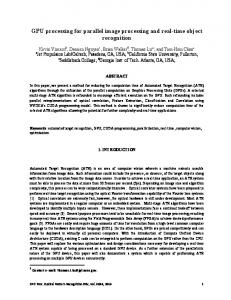
The International Journal of Virtual Reality, 2007, 6(1):35-44 set to zero, in order to specify that characters located in those areas should not be drawn. To calculate detail within the visibility polygon, vertices of this polygon are assigned a specific weight according to the distance of the point p from the camera, by using this equation:
w=
z far − z p z far
(1)
Where z far is the distance between the far plane and the near plane, and z p is the distance between the point p and the near plane. Points located in the near plane will obtain a weight of 1, while for points at the far plane will obtain a weight of 0. The visibility polygon is then rendered on the visibility plane, using the weights as grayscale values. Linear blending is used to interpolate colors within this polygon, producing the final LOD map. A sample LOD map is shown in Fig. 1.
Fig. 1. LOD map produced by the intersection of a scene plane with the viewing frustum
The appropriate level of detail for each character is compared to a certain threshold. When the detail value is greater than this threshold, this character is rendered using the instancing technique, while when the detail value is less than this threshold, an impostor is used. The threshold can be modified according to the requirements of the application and of the hardware used. If the simulation is in a low-end hardware platform, if we want high frame rates for very large crowds of characters, or if the resolution of the final application is very low, the threshold may be reduced so as to display impostors only, or to display a very small number of characters as instanced geometry. On the contrary, if we desire higher detail on the generated scenery, or if our crowds have a smaller number of characters, the threshold may be moved up so as to show more characters using detailed models. V. INCREASING CHARACTER DIVERSITY Each character of the crowd should be distinguishable from the rest. One way to achieve this is by using different geometric models for each character. However, it is not very simple to provide the simulation with several hundreds of different character models. In addition, the use of many different models increases the memory requirements for the impostor technique, as well as the amount of data sent to the graphics card for the pseudo-instancing technique. Hence, one of the best solutions to provide diverse characters is to modify different parameters that drastically the final appearance of the graphic model. People in a crowd usually have different heights. Therefore,
37
individual characters may be scaled up or down to produce the impression of taller and shorter characters. This should be done carefully, as geometric models may not appear very natural if they have very large differences in size. In addition, character animation speed should be modified according to this specific height so that movement remains natural. One of the simplest ways to generate character diversity is by changing the color of each character [16]. Color can be assigned randomly, in order to easily identify independent characters. A different technique is to specify a particular color for each character, so that color patterns are created within a crowd, or to identify certain groups of agents. In order to provide a controlled variety in appearance, a color image map may be used, setting the color of each character in a crowd according to its initial location. In this way, crowd mosaics can be created, as shown in Fig. 7. While their main purpose is producing interesting visual effects, these image maps may be useful to follow a particular set of characters through a crowd. A better appearance may be achieved by using different colors for different parts of each model. This can be done by the use of an additional texture, which describes the material for the polygons in a model. This texture can be used in the impostor generation phase in order to automatically map materials to the impostor texture. When rendering, this material index will be mapped to a specific random color that will be combined with the impostor or character texture to further enhance the variety in characters. These random colors can be restricted to be within a specific range in order to produce more predictable results for certain parts, such as skin or shoes [11]. Each character may have different materials, and each material can generate a particular color map to be used for different parts of characters in certain colors. This may be useful, for instance, in stadiums, where characters may wear the jersey of their team, but have different colors on their pants or hair In addition, distribution maps may also be used to define what parts of the image will be initially occupied by a set of images. Distribution maps may be useful to avoid the appearance of characters at places where they are not supposed to be. Together with color maps, they may also produce visually appealing results, as seen in Fig. 7. VI. SHADOWS A different kind of map that improves the appearance of crowd rendering are shadow maps. Shadow mapping [17] is a two-pass algorithm to cast shadows using a discrete map. The first pass renders a scene from the light source position. Depth information is stored into an image map, and then used in the second pass to query whether objects are occluded by shadow, and modify color values according when objects are occluded. There are many methods based on the shadow mapping technique. Adaptive shadow maps include additional detail in shadows using a hierarchical subdivision schema [18]. Perspective shadow maps modify use a projective mapping to calculate shadows only on the visible regions of the scene [19]. Visible on-screen pixels can be transformed into the light space to produce view-independent shadowing [20]. Similarly, irregular Z-buffers are used for shadow mapping, removing some artifacts by directly sampling shadows for each pixel on
38
The International Journal of Virtual Reality, 2007, 6(1):35-44
the rendered image [21]. Cascaded shadow maps use a set of shadow maps, each for a different region of the viewing frustum, increasing detail in nearby regions [22]. In this article, for simplicity, the original shadow map algorithm was used to evaluate the feasibility and impact of adding shadow mapping. However, more complex approaches may be easily integrated instead. VII. GPU IMPLEMENTATION An example implementation was programmed to evaluate the efficiency of the presented techniques aided by the graphics hardware. A set of characters was randomly distributed over a plane, according a given set of maps. Characters stand in their position, turning around using a running keyframe animation. The reference application was programmed using Open GL and GLSL. Rendering of the animated crowd involves a set of rendering passes, preceded by an initialization step.
character to verify that characters are only created within the permitted regions. This information is then copied to the graphics memory by using a pixel buffer. In this way, rendering and updating of characters may be performed internally by the graphics processor, avoiding sending information back and forth between main memory and graphics memory. Color information may be read from a color map and assigned to different materials for each individual character, according to its location on the scene. However, if a color map is not provided for a particular material, colors will be randomly generated. Once obtained, color information for each character is sent to the graphics card, using a different vertex buffer for each material. There will be as many vertex buffers created as materials are present on a character. Additional attributes, such as character size, speed, or geometric model, are generated in this step and set in different pixel buffers to be used in the rendering step. Depth buffers are also created for shadow maps. Once all information has been initialized, the application is ready for the simulation. 7.2 Pass 1. Character update In this step, the position and heading for each character is updated. A fragment program reads the character pixel buffer as a texture, and then updates the attributes for characters. In the example shown, characters are spinning in their place, so the fragment shader will only update the heading for characters. The new position and heading is then copied to a new character pixel buffer. Both character pixels buffers can be swapped after the rendering procedure has finished. This pass can also include the update of the animation frame for characters.
Fig. 2. Animation frames from an impostor texture.
7.1 Initialization Before starting the simulation, all required data is initialized. First, all images required for image maps are loaded from file. Then both the impostor and the polygonal representations for the animated characters are loaded. As impostor generation is produced in a preprocessing phase, a different application is used to produce impostor textures. Two animation frames for a custom impostor texture are shown in Fig. 2. Animation frames are contained within the same image to reduce the number of textures queried by the shader program, and thus simplify its code. Together with geometry, material maps are loaded. Material maps codify the material for a particular part of a character by using a color on a texture, and they are used both for impostors and for instanced geometry. These maps are translated into an indexed texture, where indices correspond to the material index for the pixel color, or to zero if they don’t correspond to any material. Once the geometry is loaded, the set of animated character instances is initialized. First, the location and heading for each character is generated randomly. If a distribution map is used, these positions are validated before being assigned to a
7.3 Pass 2. LOD map generation Here, the LOD map is updated according to the camera position. The LOD map is also stored into a pixel buffer. This is a quick rendering pass, as it only involves the rasterization of a single, non-textured polygon using the fixed rendering pipeline. 7.4 Pass 3. Detail Selection This pass will define the detail to be used for each character. A fragment shader uses the character position to query the LOD map texture, mapped from the pixel buffer produced by step 2. The detail value obtained is compared to a threshold parameter to verify whether the character will be rendered as an impostor or as instanced geometry. Experimentally, thresholds of 0.95 produced a good frame rate, while restricting the size of impostors to its maximum display on-screen area — related to its resolution. The detail value is also compared with a minimum display threshold, usually 0, to evaluate if that character is visible by the camera. Conditional statements are expensive in current graphics hardware. Step functions are commonly used to efficiently produce an equivalent functionality. Step functions evaluate as 0 when a value is below a certain threshold and as 1 otherwise. Hence, both threshold comparisons required can be handled by the shader program as step functions. The sum of both functions is then written on the character detail pixel buffer, and used to decide how to render each character by the following steps of the algorithm.
The International Journal of Virtual Reality, 2007, 6(1):35-44 7.5 Pass 4. Character texture expansion The character pixel map contains the position and heading for all characters on the scene. In order to display individual objects, these pixels must be copied into a vertex buffer. However, it is not possible to render a character using the impostor technique with a single vertex. While the point sprites technique [23] may display a point primitive as a textured quad, it is not yet possible with the programmable graphics hardware we are using to provide the texture coordinates for such quad. Therefore, each vertex must be expanded into a quad for rendering. An expanded pixel buffer is filled with the information from the updated character pixel buffer. Unlike passes 1 and 3, where pixel buffers of the same size are produced, this pass requires a wider image buffer, where each row will contain four times more pixels than the original texture. Each pixel from the character pixel buffer is rendered to four pixels in the expanded pixel buffer. In this way, a quad can be constructed in a later pass by using the four contiguous vertices that share the same character information. This rendering pass includes some additional processing that will eliminate a bottleneck for the next rendering pass. Texture lookups are very expensive within vertex programs [15]. In addition to the location and heading for each character, the resulting pixel buffer will also indicate whether the character will be rendered as an impostor. This is stored as the alpha component of the color in the pixel buffer, and set to 1 or -1, depending on whether the character will or will not be displayed as an impostor. After finishing this rendering pass, the expanded pixel buffer is copied into a vertex buffer, which will be used to render impostors. The alpha components produced in this pass will become the w homogeneous coordinate for the pixel. When this coordinate is set to -1, this vertex is discarded by the graphics pipeline. This will discard those characters that are not shown as impostors from the next step. Here, the LOD map is updated according to the camera 7.6 Pass 5. Impostor rendering for shadow map Before rendering impostors, the shadow map is cleared, and the camera is moved to the light position. Then, impostors are rendered on the shadow map, discarding all color information. The technique to render impostors is better described in Pass 7, except that no color information is used for this render. The LOD map produced using the scene view is also used to select which characters will be rendered as impostors and as instanced geometry, as shadows for character near the scene camera will be more noticeable than shadows for distant characters. 7.7 Pass 6. Instanced geometry render for shadow map Nearby characters are rendered using our pseudo-instancing technique. Again, color information is discarded from this rendering step to increase its efficiency. Once instanced geometry is rendered, the shadow map is read into a depth map which will be used later to render additional objects of the scene. 7.8 Pass 7. Impostor rendering The expanded vertex buffer is now used by a vertex shader to
39
display impostors in the frame buffer. In addition to character data, this pass receives the color vertex buffer that will contain the color for individual characters There are some alternatives for this corner vertex buffer. A logical choice would be the use of point sprites [23] to render each character of the crowd. However, the main drawback for point sprites is that their parameters cannot be easily manipulated from a shader program. Texture coordinates for a point sprite are not directly accessible by a shader vertex program. While they could be manipulated by a fragment program, this would increase the algorithm complexity. In addition, point size is an attribute that cannot be modified by any shader program, making complex to transform impostor size according to their distance. Instead, a corners vertex buffer is used to display a single quad for each character. The corners vertex buffer is created at the initialization phase, and will specify which one of the four vertices of the quad corresponds to which corner. The two components for this buffer are set to -1 or 1 depending on whether the vertex is the right or left — or upper or lower — corner of the quad. Additionally, the camera position and orientation, and the attributes of the impostor texture, are received as parameters. First, the position V of vertices for the impostor quad is obtained. The right vector Qx for this quad is calculated as the cross product of the camera up vector and the vector from the impostor location P to the camera. The up vector Qy for the quad will be the camera up vector. Then, the coordinates for each vertex are obtained with the formula in equation2. V = P + (Q x d x + Q y d y ) S
(2)
Where δx and δy are the values obtained from the corners vertex buffer for the current vertex, and S is the character size, as every character has different heights to increase the diversity. The texture coordinates for the current vertex are obtained by using the character heading and the direction from the character to the camera. From these parameters, the stack and slice for the current view can be determined as the closest discrete value available. These variables, as well as the current animation frame, are combined to select from the impostor texture grid the closest sub-image for the character. This sub-image is mapped to the impostor quad, and alpha testing is used to discard pixels from the background. In our sample application, we included the possibility of using different geometric models for different characters of the crowd. In order to simplify texture lookup operations, our application stored impostor textures for all different models within the same texture image. Therefore, to use a different model for a character, it is only required to slightly modify the texture coordinates for the impostor texture, instead of loading a different texture for each character and selecting such texture according to the model type. The color for the impostor is modified by two additional parameters. First, the results from the shadow mapping technique are applied to the character. According to the character position, a lookup is done in the shadow map to validate whether each pixel is occluded or not by the shadow
40
The International Journal of Virtual Reality, 2007, 6(1):35-44
map, and darken its color accordingly. Additionally, the final color for the impostor is modified according to the color for each pixel material, obtained from a lookup into the material map. To produce the final pixel color, the fragment shader multiplies the texel obtained from the impostor texture by the color and by the shadow value for that pixel. This color multiplication is comparable to the process used by the fixed graphic pipeline to combine a texture with a color and with illumination values. Finally, the fragment shader modifies the mapped texture to produce different-colored characters. A “character color” vertex buffer, similar to the “corners” vertex buffer, is generated in the initialization phase, and will produce a different color for each character. It is important to store this information so that each character maintains the same color during the application and can be identified within the crowd. To produce the final render, the fragment shader multiplies each visible pixel by the character color.
from the shadow map to darken shadowed areas of the scene. A summary of the rendering procedure is shown in Fig. 3.
7.9 Pass 8. Instanced geometry rendering Characters at full detail are drawn using instancing. However, in the hardware we have available, instancing is a feature only present in DirectX [15]. As the example application is programmed in OpenGL, we must use a different technique. Therefore, a technique based in pseudo-instancing is used. Pseudo-instancing [24] takes advantage on the efficiency of using persistent vertex attributes, such as color or transformations, to provide information for an entire instance. The main difference with instancing is that, in instancing, only one call is used to render all primitives, while pseudo-instancing requires one call to a display list to render each instance. However, these calls are very efficient in OpenGL, so similar performances are achieved by both techniques [24]. This pass requires first the generation of a set of display lists, which will later be used to display different instances. In the current example application, a reduced number of animation frames is produced. For each animation frame, a display list is produced. These display lists are sent to the graphics card. As there is a limited number of animation frames, characters use the closest animation frame to their own frame for their display. The next step consists in retrieving character information and detail from the graphics memory to the main memory. This is one of the most time consuming parts of the rendering procedure. Optimizations in this step will probably improve largely the performance of this approach. However, this was the most efficient way to display character instances available in current graphics hardware. Retrieved character detail is then used to verify which characters will be rendered as geometry instances. Characters selected for pseudo-instancing will then be rendered by calling the previously produced display lists. Character position, heading and size will be passed as color attributes, while color is passed as texture coordinates. Position, heading and size of the character will be used by a vertex program to transform the model geometry, and the color of the character will be used by a fragment program to modify the resulting color for the geometry. This fragment program will also use the information
7.10 Using geometry shaders to reduce rendering passes Geometry shaders are a new addition to programmable graphics hardware that allow to modify the way in which primitives are generated [25]. In a geometry shader, a single vertex may emit an arbitrary number of vertices for a given primitive. In our case, a single vertex may be provided for each impostor. Then, this vertex will produce a new quad primitive, setting the properties for each vertex of this new primitive. This eliminates the character texture expansion step from the proposed algorithm, and reduces the amount of data used for impostor rendering.
Fig. 3. Overview of the crowd rendering procedure. See Color Plate 15.
VIII. RESULTS The proposed technique was evaluated on a Pentium Xeon computer at 3.2 GHz using a QuadroFX 4400 graphics card with 512 MB of memory, and rendered to a 1280 x 1024 window. A different number of characters were used to evaluate the performance of the proposed technique. Rendering performance for different number of characters is shown in TABLE 1. TABLE 1: ANIMATION FRAMES FROM AN IMPOSTOR TEXTURE. Number of Minimum Maximum characters frame rate frame rate No shadows 214 – 16,384 59.3 fps 60.0 fps 216 – 65,536 49.5 fps 60.0 fps 217 – 131,072 30.7 fps 37.8 fps 218 – 262,144 15.7 fps 19.8 fps 219 – 524,288 8.0 fps 10.1 fps 220 – 1,048,576 4.3 fps 5.1 fps Using shadow mapping 214 – 16,384 58.1 fps 60.0 fps 216 – 65,536 21.6 fps 27.3 fps 218 – 262,144 6.8 fps 7.9 fps 220 – 1,048,576 1.4 fps 1.7 fps
Maximum frame rates were achieved when rendering all characters as impostors, while minimum frame rates involved a mixed rendering of impostors and instanced geometry. In order to select the detail for each character, a 256×256 LOD map was
The International Journal of Virtual Reality, 2007, 6(1):35-44 used. Characters were rendered to a 1,280×1,024 window. For shadow rendering, a 1,024×1,024 shadow map was used. The crowds that were generated had a maximum number of 220 characters due to the maximum texture size of 2,048×2,048 pixels supported by our graphics hardware. As the expanded character texture requires four pixels per character, this allows a maximum of 512×2,048 (1,048,576) characters per texture. Memory requirements of 152 bytes per character are constant for character rendering. Half-float textures were used to reduce memory usage to two bytes per channel, and eight bytes per RGBA pixel. Each buffer has different memory requirements, shown in Table 2. LOD map and shadow map generation does not depend on the number of characters, but good results can be achieved with 128×128 LOD maps, adding 16KB of memory to the algorithm, and 1,024×1024 shadow maps, adding 1MB of memory to the algorithm. Lower resolution shadow maps can produce better results when different shadowing techniques are incorporated, such as perspective or cascaded shadow maps. 152 MB of memory are required to produce a million characters. While is a large amount of memory, recent graphics hardware include up to 768 MB of memory, leaving a good amount for the scene itself. However, rendering a million characters is a rather complex task that requires many computational resources, and is hard to achieve at good frame rates on a single computer. Memory requirements for the impostor textures vary according to the number of animations, frames, and viewpoints. A walking animation of 6 frames using 16×8 viewpoints with 64×64 pixels impostors requires 3 MB of texture memory per character. Changing the number of frames to 18 and the number of viewpoints to 16×16 increases the required memory to 18 MB, which is still a small amount compared to memory used by the character buffers. However, this amount can be reduced, by using greyscale impostor textures and combining them with character colors. There are some techniques for impostor texture compression [12] that can be adapted to work on the graphics processor. Some of the renders for the example application are illustrated in Fig. 4. Here, a gap is left between impostors and instanced geometry to help identifying both approaches on the image. The decision to use different colors for each character was motivated by these results. The use of a single colored model for every character would make it even more difficult to distinguish individual characters within the crowd. TABLE 2: MEMORY REQUIREMENTS FOR DIFFERENT NUMBER OF CHARACTERS. Number of characters Characters Updated chars. Character detail Expanded Pixel Expanded Vertex Corners Character Color Size / Frame / Model Total
1 8B 8B 8B 32B 32B 16B 24B 24B 152B
16 K 128 B 128 B 128 B 512KB 512KB 256KB 368KB 368KB 2.4MB
64 K 512KB 512KB 512KB 2MB 2MB 1MB 1.5MB 1.5MB 9.5MB
256 K 2MB 2MB 2MB 8MB 8MB 4MB 6MB 6MB 38MB
1M 8MB 8MB 8MB 32MB 32MB 16MB 24MB 24MB 152MB
While the render of 1,048,576 characters provided a relatively low frame rate of between 4.3 and 5.0 frames per second, the crowd is very large for the window resolution used.
41
A crowd of 262,144 characters produces a better frame rate and still gives a similar appearance. Character size may also be enlarged to give the appearance of a large crowd with a smaller number of characters. Here, a smaller character size was used to better appreciate the crowd density.
a)
b)
c)
d)
Fig. 4. Display of different size crowds. a) 16 K characters. b) 64 K characters. c) 256 K characters. d) 1 M characters.
Having a set of characters spinning in their own place is not a very common behavior in videogames or in any graphics application. Hence, the proposed rendering technique was integrated with another application, where character behavior is simulated within the graphics processor [26]. In order to do this, step 1 from the rendering algorithm was replaced by the programmable Finite State Machine simulation proposed in our previous work. In the presented example, characters are programmed to go from one region to other and back.
a)
b)
Fig. 5. Display of different size crowds using FSM simulation on the GPU. a) 512 K characters. b) 1 M characters.
Using only pseudo-instancing, the simulation was only capable of displaying 16,384 characters at only 5.45 frames per second. By integrating the proposed rendering technique, the resulting performance was very similar to that of the spinning characters: between 59 and 60 frames per second for 16,384 characters, between 29.9 and 60 fps for 65,536 characters, and between 3.1 and 4.6 fps for 1,048,576 characters. The main reason of the frame rate reduction is that in certain moments, the number of characters rendered at full detail is higher than in the spinning example. Two screenshots of this simulation are shown in Fig. 5. Fig. 6 shows simulation of different crowds of characters rendered using shadow mapping. When a crowd is very large, most regions on the floor are covered by characters and it is hard to distinguish their projected shadows. For a smaller number of characters, shadows can be seen, but the resolution
The International Journal of Virtual Reality, 2007, 6(1):35-44
42
of the shadow map is small compared to the large number of characters on the scene.
a)
b)
c)
d)
Fig. 6. Display of different size crowds using shadow mapping. a) 16 K characters, b) 64 K characters, c) 256 K characters, d) 1 M characters
eliminating the corners information, memory requirements are reduced to 23% of the original memory requirements, using only 36 bytes for each character instead of the 152 bytes used by in the initial approach.
Fig. 8. Use of different materials in a crowd. See Color Plate 17.
Interesting results were obtained from the combination of color and distribution maps. A crowd of characters mimicked a picture by setting a specific color map of such picture. Distribution maps produce a highlighting effect on certain objects of the scene. It is also interesting to mention that, as crowds are intended to have a specific behavior, the overall look of the crowd changes the appearance of the image as the simulation advances. Some of the results of using these maps are shown in Fig. 7. The use of different materials for characters greatly increases the diversity of appearance within a crowd. As seen in Fig. 8, characters appear dressed with different outfits. An advantage of material maps is that certain areas of characters can be left with their original color, as the skin of characters, avoiding the appearance of non-natural colors. In addition, different colors may be either randomly generated, as in Fig. 8, or loaded from a set of image maps. TABLE 3: MEMORY REQUIREMENTS FOR DIFFERENT NUMBER OF CHARACTERS GEOMETRY SHADERS.
Fig. 7. Top row: Color map applied to a crowd of 256K characters. Middle row: Color map and distribution map applied to a crowd of 64K characters. Bottom row: Color and distribution maps for both simulations. Color Plate 19
Traditional shadow mapping produces acceptable results using a large shadow texture. However, shadow mapping for crowds can definitely be improved by using different techniques. Again, a level-of-detail technique, such as such as perspective shadow maps [19] or cascaded shadow maps[22], should be implemented for shadows, providing better detail for shadows near the camera, and reducing the shadow quality for shadows away from the camera. This may also reduce the size of the shadow map used, producing similar results. Even when the use of geometry shaders eliminates a step from the crowd rendering pipeline, very similar rendering times were achieved by both approaches. However, there are considerable reductions in memory use, as seen in TABLE 3. There, it can be seen that, by including geometry shaders and
Number of characters Characters Updated chars. Character detail Character Color Size / Frame / Model Total
1
16 K
64 K
256 K
1M
8B 8B 8B 6B 6B 36B
128 B 128 B 128 B 96KB 96KB 576MB
512KB 512KB 512KB 384KB 384KB 2.25MB
2MB 2MB 2MB 1.5MB 1.5MB 9MB
8MB 8MB 8MB 6MB 6MB 36MB
IX. CONCLUSION An efficient technique has been presented to display large crowds of animated characters at interactive frame rates. As graphic processors become more powerful and common, the use of this approach may enable the interactive display of even larger crowds. Impostors are a technique that is well suited for graphics processors, as a constant single quad is required to display each character; its animation and transformations are based on simple texture lookups. Different thresholds between pseudo-instancing and impostors can be used for different applications. A lower threshold can be used in realistic virtual reality simulations, where powerful hardware enables the production of higher
The International Journal of Virtual Reality, 2007, 6(1):35-44 resolution images. Here, as characters will be rendered to a larger on-screen area, the use of more instanced geometry will produce more realistic results. In contrast, console videogames and applications for commodity hardware may rely on a higher threshold, improving the rendering performance for such applications. Furthermore, these applications may even eliminate the pseudo-instancing stage, avoiding the transfer of character data to main memory, and thus producing an even better performance, though with less detail. While this distance threshold variability is useful to customize the detail of the characters according to the capabilities of the rendering hardware, a better metric may be used to switch between both representations. This metric could be obtained from the impostor generation phase; thresholds for image maps could be obtained as a function of the distance between the characters and the camera in the impostor generation phase, and of the image resolution of the produced impostor. The number of displayed characters exceeds at least by an order of magnitude existing algorithms for rendering. Reynolds was able to produce crowds of 10,000 characters at 60 frames per second on Playstation 3 hardware [27]. Other approaches have reached between 1,000 and 30,000 characters at interactive frame rates [11, 13], adding features not present in our initial rendering approach. In particular, Dobbyn [13] uses a set of texture maps to improve rendering: normal maps for per-pixel lighting, region maps to assign different colors to different parts of the character, and detail maps. This rendering technique produces a more realistic appearance. Our rendering system uses a simplified version of behavior simulation and does not calculate illumination or shadows, but is capable of displaying more than 60,000 characters at 60 fps, and many more at interactive frame rates. While this is an initial approach, the efficiency obtained by these results encourages the extension of this algorithm to include further improvements in rendering. Shadow mapping reduces the performance of our algorithm almost to the half. This is due to the additional rendering passes required to render the shadow map, and to the per-pixel shadow map querying for the rendered image. Nevertheless, it is still possible to render more than 16,000 characters at 60 fps, and more than 60,000 at interactive frame rates. Character diversity is greatly improved by adding different models, changing the size and the animation frame for each character. These three variations just need additional 24 bytes per character. Some other improvements should be explored to further improve the appearance of rendered characters. The use of color and distribution maps produces interesting visual effects. While this is not the direct intention of this article, the effects produced by motion of characters of a scripted crowd may be an unexplored tool to produce different crowd-based image filters, where character behavior is guided by the color or position of individual characters within a crowd. Character behavior is extremely simple in the application shown here. Better algorithms for character simulation, executed either by the main processor or by the graphics hardware, should be evaluated to produce more interesting character behaviors for videogames or other applications.
43
Using finite state machines represented as image maps [26] is a starting point, but better ways to specify complex behaviors should be developed. Finally, next generation graphics hardware should be thoroughly evaluated, as upcoming features, such as geometry shaders, animated instancing, or vertex shaders texture lookups, may provide with additional functionality that may be harnessed to improve the flexibility and efficiency of GPU crowd rendering. The ability of rendering an entire quad providing a single vertex has been tried and reduces the memory requirements of our approach by more than a 75% of the current requirements. ACKNOWLEDGMENT The authors would like to thank the ITESM IVE Project. REFERENCES [1] [2] [3] [4]
[5]
[6] [7]
[8]
[9] [10]
[11]
[12] [13]
[14]
G. Turk. Retiling polygonal surfaces, Computer Graphics, vol. 26, no. 2, pp. 55–64, 1992. H. Hoppe. Progressive meshes, in Proceedings of the 23rd annual conference on Computer graphics and interactive techniques. ACM Press, pp. 99–108, 1996. J. P. Grossman and W. J. Dally. Point sample rendering, in Rendering Techniques’98. Springer, pp. 181–192, 1998. S. Rusinkiewicz and M. Levoy. QSplat: A multiresolution point rendering system for large meshes, in Proceedings of the 27th annual conference on Computer graphics and interactive techniques. ACM Press / Addison Wesley Publishing Co., pp. 343–352, 2000. H. Pfister, M. Zwicker, J. van Baar and M. Gross. Surfels: surface elements as rendering primitives, in Proceedings of the 27th annual conference on Computer graphics and interactive techniques. ACM Press/Addison-Wesley Publishing Co., pp. 335–342, 2000. M. Wand and W. Straßer. Multi-resolution rendering of complex animated scenes, Computer Graphics Forum, Eurographics 2002, vol. 21, no. 3, 2002. I. Rudomín and E. Millán. Point based rendering and displaced subdivision for interactive animation of crowds of clothed characters, in VRIPHYS 2004: Virtual Reality Interaction and Physical Simulation Workshop. Mexican Society of Computer Science, SMCC, pp. 139–148, 2004. A. Aubel, R. Boulic and D. Thalmann. Animated impostors for realtime display of numerous virtual humans, in VW ’98: Proceedings of the First International Conference on Virtual Worlds. London, UK: Springer-Verlag, pp. 14–28, 1998. F. Tecchia and Y. Chrysanthou. Real-time rendering of densely populated urban environments, in Proceedings of the Eurographics Workshop on Rendering Techniques 2000. Springer, pp. 83–88, 2000. A. Aubel, R. Boulic and D. Thalmann. Lowering the cost of virtual human rendering with structured animated impostors, in Proc. 7th Int’l Conf. in Central Europe on Computer Graphics, Visualization, and Interactive Digital Media (WSCG 99). Univ. of West Bohemia Press, 1999. P. de Heras Ciechomski, S. Schertenleib, J. Mam, D. Maupu and D. Thalmann. Real-time shader rendering for crowds in virtual heritage, in The 6th International Symposium on Virtual Reality, Archaeology and Cultural Heritage. Pisa, Italy: Eurographics Association, pp. 91–98, 2005. F. Tecchia, C. Loscos and Y. Chrysanthou. Image-based crowd rendering, IEEE Comput. Graph. Appl., vol. 22, no. 2, pp. 36–43, 2002. S. Dobbyn, J. Hamill, K. O’Conor and C. O’Sullivan. Geopostors: A real-time geometry / impostor crowd rendering system, in SI3D ’05: Proceedings of the 2005 symposium on Interactive 3D graphics and games. New York, NY, USA: ACM Press, pp. 95–102, 2005. E. Millán and I. Rudomín. A comparison between impostors and point-based models for interactive rendering of animated models, in Proceedings of the International Conference on Computer Animation and Social Agents (CASA) 2006. University Press, July 2006.
44
The International Journal of Virtual Reality, 2007, 6(1):35-44
[15] P. Scott. Shader model 3.0, best practices, NVIDIA Corporation, Tech. Rep., 2004, available online at http://developer.nvidia.com/object/SM3_0_best_practices.html. [16] E. Millán and I. Rudomín. Impostors and pseudo-instancing for GPU crowd rendering, in GRAPHITE ’06: Proceedings of the 4th international conference on Computer graphics and interactive techniques in Australasia and South East Asia. New York, NY, USA: ACM Press, pp. 49–55, 2006. [17] L. Williams. Casting curved shadows on curved surfaces, in SIGGRAPH ’78: Proceedings of the 5th annual conference on Computer graphics and interactive techniques. New York, NY, USA: ACM Press, pp. 270–274, 1978. [18] R. Fernando, S. Fernandez, K. Bala and D. P. Greenberg. Adaptive shadow maps, in SIGGRAPH ’01: Proceedings of the 28th annual conference on Computer graphics and interactive techniques. New York, NY, USA: ACM Press, pp. 387–390, 2001. [19] M. Stamminger and G. Drettakis. Perspective shadow maps, in SIGGRAPH ’02: Proceedings of the 29th annual conference on Computer graphics and interactive techniques. New York, NY, USA: ACM Press, pp. 557–562, 2002. [20] T. Aila and S. Laine. Alias-free shadow maps, in Proceedings of Eurographics Symposium on Rendering 2004. Eurographics Association, pp. 161–166, 2004. [21] G. S. Johnson, J. Lee, C. A. Burns and W. R. Mark. The irregular Z-buffer: Hardware acceleration for irregular data structures, ACM Trans. Graph. , pp. 1462–1482, vol. 24, no. 4, 2005. [22] W. Engel. Cascaded shadow maps, in ShaderX5 - Advanced Rendering Techniques, W. Engel, Ed. Charles River Media, Inc., ch. 8.1, pp. 197–206, 2006. [23] ARB. ARB point sprite extension, OpenGL Architecture Review Board, Tech. Rep., 2003, available online at http://oss.sgi.com/projects/ogl-sample/registry/ARB/point sprite.txt. [24] J. Zelsnack. GLSL pseudo-instancing, NVIDIA Corporation, Tech. Rep., 2004, available online at http://download.nvidia.com/developer/SDK/Individual Samples/ samples.html. [25] ARB. Geometry program extension, OpenGL Architecture Review Board, Tech. Rep., 2003, available online at http://oss.sgi.com/registry/specs/NV/geometry_program4.txt. [26] Rudomín, E. Millán and B. Hernández. Fragment shaders for agent animation using finite state machines, Simulation Modelling Practice and Theory, vol. 13, no. 8, pp. 741–751, November 2005. [27] C. Reynolds. Crowd simulation on PS3, in Game Developers Conference 2006, 2006. Erik Millan. Erik Millan is a Ph.D. Student of computer science at the Tecnologico de Monterrey, Campus Estado de Mexico. He is completing his thesis on specification and simulation of crowd behavior. He received his master's degree at the same institution, working on plant modeling based on particle systems. His research interests include crowd simulation, GPGPU, procedural modeling, level of detail techniques, and computer vision.
Isaac Rudomín. Isaac Rudomin received his Ph.D. in computer science from the University of Pennsylvania. He has been a professor at the Tecnologico de Monterrey, Campus Estado de Mexico, since 1991. He is the author of about 50 technical papers. His research interests include human modeling and crowd animation as well as the use of graphics processors.