Harnessing logic inference capability of logic programming languages, we obtain an automated method that infers all the instances of a design pattern in a UML ...
Inference of Design Pattern Instances in UML models via Logic Programming Dae-Kyoo Kim and Lunjin Lu Department of Computer Science and Engineering Oakland University Rochester, MI 48309 (kim2, l2lu)@oakland.edu
Abstract This paper formalizes the notion of a design model structurally conforming to a design pattern by representing the model as a logic program whilst the pattern as a query. The conformance of a model to a design pattern is equivalent to the satisfaction of the query by the logic program. Harnessing logic inference capability of logic programming languages, we obtain an automated method that infers all the instances of a design pattern in a UML class diagram. We use the Visitor pattern and a price calculation application to demonstrate the technique.
1 Introduction Design patterns have been an important research subject in the area of software engineering, particularly in reusebased software engineering since their introduction in computer science [8]. A design pattern describes a proven solution based on the previous experience to a recurring design problem in a reusable form (e.g., see [13]). By reusing high quality solutions, design patterns help the development of systems that are extensible, flexible and maintainable [28]. Evaluation of pattern conformance of designs is concerned with checking valid realizations of a pattern in a design within the context of the application being built. In general, realizing a pattern heavily relies on designer’s experience and knowledge of the pattern. Invalid realization of a pattern, however, could deteriorate rather than improve quality of design. Then, a question that naturally arises is “how can one ensure validity of a pattern realization?” The question can be partly addressed by pattern formalization efforts (e.g., see [9, 14, 17, 20, 21, 24, 26, 31]) that facilitate pattern realization (instantiation). For example, templatebased approaches (e.g., [31]) formalize patterns in terms of parameters, and a pattern can be instantiated (realized) by stamping out the template. However, in many cases, instantiated pattern realizations require significant modifications
such as adding new elements, modifying or removing some instantiated elements to accommodate application-specific requirements. Since these activities may break pattern conformance and compromise the benefits of using design patterns, pattern conformance must be checked. There has been much work [2, 4, 5, 7, 10, 15, 16, 27, 30] on identifying pattern instances in code at the programming level where structural properties (e.g., operations, attributes, relationships) of design patterns [13] are searched in code. These works support the reverse engineering efforts at the programming level so as to understand legacy systems and improve their quality attributes. However, there is little work on validating pattern instances at the model level which can greatly improve the quality of design and reduce development cost by finding errors in early development phase. Based on our study, we found that some of the programming-level work (e.g., [7, 16, 27]) can be extended for detecting model-level pattern instances. However, a significant limitation found in these approaches is that pattern specifications are used to represent a typical instance of design pattern and they are used to find exact matching structures in different applications. This limits the applicability of these approaches because in most cases, a design pattern is realized in various forms depending on the application domain, and thus it is very rare to find the same instance in different designs. To address this issue, we use logic programming to rigorously check pattern conformance of class diagrams described in the Unified Modeling Language (UML) [31]. We represent a design pattern as a query and a class diagram as a logic program. A class diagram is said to conform to a pattern if the logic program representing the class diagram satisfies the query representing the pattern. In this way, we obtain a concise and precise formalisation of the notion of the model conforming to the pattern. This provides a semantic basis for automatic inference of the instances of the pattern in the model. By utilizing inference capability of the logic programming language Prolog, we obtain an automated method that infers all the instances of the pattern in
Proceedings of the 11th IEEE International Conference on Engineering of Complex Computer Systems (ICECCS'06) 0-7695-2530-X/06 $20.00 © 2006
the model. We base our work on pattern specifications described in the Role-Based Metamodeling Language (RBML) [12, 17]. We chose the RBML because it precisely describes pattern properties and is designed to support model-level use of design patterns for UML models. To demonstrate the technique, we use the Visitor pattern [13] and a model of a price calculation application that calculates the total net price for a composite equipment. The main contribution of this work is the representation scheme in which a class diagram is represented as logic programs and a pattern as a query. The representation scheme facilitates use of design patterns in software development as follows: • The scheme can be used to find all instances of the pattern in the model by executing the program for the query. Each answer to the query is an instance of the pattern in the model. Thus, our approach does not simply tell if the model satisfies the pattern but also informs “how” the model satisfies the pattern. Using a debugging technique [29, 23], one can also identify the cause of non-conformance in the model if the query does not have any answer. • The scheme can be used to validate designer’s assignment of pattern roles to model elements. During the development of a software model, the designer may designate certain elements to play particular pattern roles. The scheme can be used to validate this assignment by representing the assignment as an equality constraint and executing the constraint and the query with the program. Furthermore, given a partial mapping of pattern roles and model elements, the scheme can complete the mapping by logic inference. The remainder of the paper is organized as follows. Section 2 gives an overview of the RBML and Section 3 presents an RBML specification of the Visitor pattern. Section 4 describes how patterns and class diagrams can be represented in Prolog using the Visitor pattern and a price calculation application as examples. Section 5 describes inference of valid pattern instances based on the representation. Section 6 gives an overview of related work, and Section 7 concludes the paper.
2 Role-Based (RBML)
Metamodeling
Language
The RBML [17] is a UML-based pattern specification language that is designed to support the development of pattern-based UML models. The RBML specifies patterns in terms of roles where a role defines a set of constraints. A role has a base metaclass in the UML metamodel, and is
played by instances of the metaclass that satisfy the properties specified in the role 1 . The RBML provides three types of specifications to capture various perspectives of pattern properties [17]: Static Pattern Specifications (SPSs), Interaction Pattern Specifications (IPSs), and Statemachine Pattern Specifications (SMPSs). In this work, we restrict ourselves to SPSs only. An SPS specifies class diagram views of pattern solutions, that is, it characterizes a family of solution class diagrams for a pattern. An SPS consists of classifier and relationship roles whose bases are Classifier and Relationship metaclasses in the UML metamodel. A classifier role is associated with a set of feature roles that determines the characteristics of the classifier role and is connected to other classifier roles by relationship roles. Class Role |RoleA |Str: Int 1..*
1
|AssocRole 1..* |EndA 1..*
|EndB 1..1
Class Role 2..* |RoleB |Behv (|o:|RoleA) 1..*
Figure 1. A Static RBML Specification Fig. 1 shows an example of an SPS. In the SPS, there are two class roles RoleA and RoleB whose base is the Class metaclass (as denoted above their name), which constrains that only instances of the Class metaclass can play the roles. RoleA has a structural feature role Str whose data type is integer. This further restricts the instances that can play RoleA in that they must possess a structural feature with integer data type. RoleB has a behavioral feature role Behv with a parameter role o whose type is RoleA. The class roles are connected by association role AssocRole that has two association end roles EndA and EndB. Each role defines a role multiplicity (shown near the role name) constraining the number of elements that can play the role. For example, RoleA has 1..* role multiplicity constraining that there can be one or more elements playing the role. A role is associated with a set of metamodel-level constraints. Metamodel-level constraints specialize the UML metamodel by restricting the type of model elements that can play the role. They are represented graphically in diagram or textually in the Object Constraint Language (OCL) [33]. For example, in Fig. 1 RoleA has three metamodellevel constraints represented graphically: 1) the base metaclass constraint Class requires that a model element playing the RoleA role must be a class (an instance of the Class metaclass), 2) the structural feature constraint Str demands that a model element playing the RoleA role must have one or more structural features playing the Str role, 3) the role 1 Note that the notion of roles in the RBML is different from the one in the UML in that RBML roles are defined at the metamodel level and played by model elements, while UML roles are defined at the model level and played by objects (for details, see [18])
Proceedings of the 11th IEEE International Conference on Engineering of Complex Computer Systems (ICECCS'06) 0-7695-2530-X/06 $20.00 © 2006
multiplicity constraint 1 postulates that there must be exactly one class playing RoleA. The SPS also has the following OCL metamodel-level constraints: • Classes playing RoleA must be concrete: context |RoleA inv: self.isAbstract = false • Association ends playing EndA must have a multiplicity of 1: context |EndA inv: self.lowerBound() = 1 and self.upperBound() = 1 • Association ends playing EndB must have a multiplicity in the range of 1..*: context |EndA inv: self.lowerBound() = 1 and self.upperBound() = *
class in the model that can play the role, and 4) it is concrete. ClassA may have properties not participating in the pattern (e.g., att2). ClassB and ClassC are described similarly. The two association ends on ClassA conform to the metamodel-level constraints of the EndA role since a) they both have an object multiplicity of 1, and b) the number of the association ends playing the role EndA is 2, satisfying the role mulitiplicity 1..* of the EndA role. Similarly, both the association end on ClassB and the association end on ClassC satisfy the metamodel-level constraints of the EndB role. A noteworthy point is that even though the object multiplicities 2, 3..*) on these two ends are not exactly same as 1..* as described in the OCL, they satisfy the constraint because they are within the range of 1..*.
3 Visitor Pattern Specification 2.1
Static Pattern Specification Conformance
In this work, we use SPSs of a design pattern to evaluate pattern conformance of a UML class diagram. A class diagram is said to structurally conform to an SPS when the model satisfies the metamodel-level constraints specified in the roles of the SPS. In order for a class diagram to conform to an SPS, the class diagram must posses model elements that can play the roles in the SPS, that is, the model elements must satisfy the constraints defined in the roles.
In this section, we give an example of an SPS for the Visitor pattern [13]. The Visitor pattern provides a solution for handling crosscutting operations in a structure of classes called elements by putting these operations into separate classes called visitors and having the visitors visit the elements to perform the operations on the elements. Class Role 1..* |ObjectStructure |Obj 1..1 Association Role |ObjStructElem
Class Role |RoleA
1
conforms
ClassA |Elem 1..*
att1: Int att2: String
|Str: Int 1..*
Class Role |Visitor
1 1
|EndA 1..*
1..*
|VisitElem(|elem:|Element) 1..*
Dependency Role |VisitElemDep
|Client 1..1
|Supplier 1..1
Classifier Role |Element
1..*
|Accept(|vis:|Visitor) 1..1 |Operation() 1..*
|AssocRole 1..* |EndB 1..1 Class Role |RoleB
2..*
|Behv (|o:|RoleA) 1..*
(a) SPS
2 ClassB op1(a:ClassA) op2()
3..* ClassC op(a:ClassA)
(b) Class Diagram
Figure 2. Examples of Conforming Class Diagrams
Fig. 2 shows an example of a class diagram conforming to the SPS in Fig. 1. In the example, ClassA conforms to the metamodel-level constraints of RoleA described above because 1) ClassA is an instance of the Class metaclass, 2) it has an attribute whose type is integer, 3) it is the only
Figure 3. A Partial SPS for the Visitor Pattern Fig. 3 shows a partial SPS of the Visitor pattern. The SPS characterizes class diagrams that have classes playing Visitor, Element, and ObjectStructure roles and relationships playing VisitElemDep and ObjStrucElem roles. The Visitor role specifies that there must be at least one or more classes (denoted by the role multiplicity 1..*) playing the role, and the visitor classes must have one or more behavioral features for visiting elements to carry out necessary operations on the elements. The Element role specifies that element classes must have one operation that accepts the visitor and operations to be performed by the visitor. The ObjectStructure role specifies that there should be exactly one class playing the role that defines the structure of Element objects on which the visitors travel. The properties (e.g., role multiplicities, base metaclasses) of the SPS shown in the diagram are metamodel-
Proceedings of the 11th IEEE International Conference on Engineering of Complex Computer Systems (ICECCS'06) 0-7695-2530-X/06 $20.00 © 2006
level constraints expressed graphically. Other metamodellevel constraints difficult to express in the diagram are described in the OCL. The following are some of the OCL metamodel-level constraints defined for the Visitor SPS: • Classifiers that play the Visitor role must be concrete classes: context |Visitor inv: self.isAbstract = false
PricingVisitor total:Currency
EquipmentStructure equipmentList:List
Note that the Visitor SPS is developed to be partial for simplicity of the demonstration of the technique. A full SPS would include properties constraining that there should be a corresponding VisitElem operation for every concrete Element classes. To specify this, the SPS should be extended with role hierarchies that involve the notion of abstract and concrete roles (for details, see [18]).
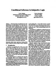
4 Representing Patterns and Models in Prolog In this and the next sections, we describe how logic programming rigorously evaluates pattern conformance using a model of a price calculation application and the visitor pattern SPS presented in Section 2. The application calculates the total net price of a composite equipment from the net prices of its parts using the Visitor pattern. Fig. 4 shows the class diagram. The diagram describes equipment structures that consist of cards and chassises where a chassis is a composite equipment of cards. A PricingVisitor object visits each element in the equipment structure and gets its net price in order to calculate the total net price of the equipment. Operations visitCard and visitChassis are used to visit Card and Chassis objects. A visited element accepts the visitor object and
1..*
accept(v:PricingVisitor) netPrice():Currency
consists−of 1..*
0..1
composed−of
attach(e:Equipment) detach(e:Equipment) accept(v:PricingVisitor)
0..1 Card
1
accept(v:PricingVisitor)
drives 1
CompositeEquipment addEquip() removeEquip() accept(v:PricingVisitor)
Client
• Dependencies that play the VisitElemDep role must be usage dependencies: context |VisitElemDep inv: self.stereotype.name = “usage”
• An association end playing the Elem role must have a multiplicity of 1..* and be navigable: context |Elem inv: self.lowerBound() = 1 and self.upperBound() = * and self.isNavigable = true
name:String netPrice:Currency required:Boolean
visitCard(c:Card) visitChassis(c:Chassis)
• Classifiers that play the ObjectStructure role must be concrete classes: context |ObjectStructure inv: self.isAbstract = false
• An association end playing the Obj role must have a multiplicity of 0..1 and not be navigable: context |Obj inv: self.lowerBound() = 0 and self.upperBound() = 1 and self.isNavigable = false
Equipment
Chassis accept(v:PricingVisitor)
Figure 4. A Class Diagram of a Price Calculation Application
returns itself to the visitor. The visitor then calls the netPrice operation to the element to get its net price. A prerequisite for any automated tool for reasoning about UML design models is a representation scheme for model elements. A logic program is declarative in that it describes what a problem is but not how it can be solved. Solutions to the problem can be generated by a logic programming language system such as Prolog. The domain of the problem is described as a collection of logic statements and so is the problem. Logic inference capability of a logic programming language such as Prolog can not only check if the problem is solvable but also can find all solutions to the problem.
4.1
Models as Logic Programs
This section presents a scheme for representing model elements of a UML class diagrams and its associated OCL constraints as Prolog statements. A class diagram is composed of types and relationships between them. A type is an interface, a class or a classifier while a relationship is a dependency, an association or an inheritance. We will consider only the above types and relationships in this paper. Other kinds of types and relationships can be dealt with similarly. Kinds of type: These are different kinds of types such as classifiers, classes and interfaces. Each kind corresponds to a unary predicate with the name of the type as its argument. For instance, the equipment type is an abstract type, which is represented by the Prolog fact abstract class(equipment).
Proceedings of the 11th IEEE International Conference on Engineering of Complex Computer Systems (ICECCS'06) 0-7695-2530-X/06 $20.00 © 2006
The kinds of types in Fig. 4 are represented by the following Prolog facts. abstract_class(equipment). concrete_class(card). concrete_class(pricingVisitor). concrete_class(chassis). concrete_class(equipmentStructure). concrete_class(client). concrete_class(compositeEquipment). Features of type: A type has a number of attributes, operations, association ends and dependency ends (suppliers and clients). These are called features of the type. That a type has a feature is represented as a fact of the form has feature(TName, Info) where TName is the name of the type and Info is a ground term describing the feature. Operations and Attributes: That a type has an operation is represented as a Prolog fact has feature(TName, op(OpName, ArgTypes, RType)). TName is the name of the type, OpName the name of the operation, ArgTypes the list of its argument types and RType the type of its returned value. For example, the only operation defined in the chassis class in Fig. 4 is represented by has feature(chassis,op(accept,[pricingVisitor],void)) and the operations defined in the equipment class are encoded as these Prolog facts. has_feature(equipment, op(accept,[pricingVisitor],void)). has_feature(equipment,op(netPrice,[],void)). Attributes are treated similarly. That a type has an attribute is represented as a Prolog fact of the form has feature(TName,attr(AttrName,AttrType)) where TName is the name of the type, AttrName the name of the attribute and AttrType the type of the attribute. For instance, the attributes of the equipment class are encoded as these Prolog facts. has_feature(equipment,attr(name,string)). has_feature(equipment,attr(netPrice,currency)). has_feature(equipment,attr(required,boolean)). Association and Dependency: An association has two association ends that may be annotated with object multiplicity and navigability constraints. An association is uniquely identified with its two ends. Thus, an association is represented by representing its ends. An association end of a type is represented by a fact has feature(TName,assoc( AssocName, Navigability, bounds(Lower,Upper))) where TName is the name of the type that participates in the association at the end. AssocName is the name of the association. Navigability is either true or false, indicating whether the end is
navigable. Lower is the lower bound on the object multiplicity at the end and Upper the upper bound. For instance, the association composedOf is represented by these two facts: has_feature(equipment, assoc(composedOf,false,bounds(1,many))). has_feature(compositeEquipment, assoc(composedOf,true,bounds(0,1))). Dependency relationships are represented in a similar way as association relationships. A dependency end of a type is represented by a Prolog fact of the form has feature(TName,depend(DependName,Navigability)) where TName is the name of the type, DependName the name of the dependency that the type participates at that end. Navigability at two ends of a dependency is used to indicate the direction of the dependency. The only dependency uses in Fig. 4 is represented by these two facts. has_feature(equipment,depend(uses,true)). has_feature(pricingVisitor,depend(uses,false)). Inheritance: Inheritance relationships induce a subtyping relation between types. The relation is represented by a predicate is a such that is a(T1,T2) indicates that T1 is a sub-type of T2. The sub-typing relation in Fig. 4 is represented as follows. is_a(compositeEquipment,equipment). is_a(chassis,compositeEquipment). is_a(card,equipment). Metamodel knowledge The Prolog facts obtained as above are model specific. They are complemented with Prolog rules that represent metamodel knowledge. The set of types of one kind may be contained in the set of types of another kind. The containment relationship between two kinds is represented by a Prolog rule of the form Kind 1(X) :- Kind 2(X) where X is a variable, indicating that types of Kind 2 are also types of Kind 1. For instance, that both interfaces and classes are classifiers is encoded by the following Prolog rules. classifier(X) :- interface(X). classifier(X) :- class(X). and that both concrete and abstract classes are classes is encoded as class(X) :- abstract_class(X). class(X) :- concrete_class(X). The knowledge that the sub-typing relation is transitive is encoded by this Prolog rule: is a(X,Y) :- is a(X,Z), is a(Z,Y). Since inheritance is non-cyclic, a call to is a/2
Proceedings of the 11th IEEE International Conference on Engineering of Complex Computer Systems (ICECCS'06) 0-7695-2530-X/06 $20.00 © 2006
with its first argument being a ground term is guaranteed to terminate universally. The translation from patterns to queries ensures that is a/2 is always called with its first argument ground. Sub-typing induces a rule for inherited features: has_feature(T,F) :- is_a(T,T1),has_feature(T1,F). The program that represents the UML model consists of the facts and rules obtained as above and the following rules that realizes the containment relation between pairs of object multiplicity bounds. bounds_subset(bounds(L1,U1),bounds(L2,U2)) :bound_leq(L2,L1), bound_leq(U1,U2). bound_leq(B1,B2) :B2 == many -> true; B1 \== many, B1 =< B2. The predicate bounds subset will only be used to check a given pair of bounds is contained in another given pair of bounds; it will not be used to generate the containment relation between pairs of bounds.
4.2
Patterns as Queries
The goal of inference is to discover a mapping from pattern roles to model elements such that when the roles are substituted by the model elements, the pattern is satisfied by the model. For this purpose, we represent a design pattern as a query. The representation uses the same predicates for representing UML models. Each role is represented as a variable. Roles except association end roles are represented as atoms in the same way as their corresponding model elements are represented as facts. For instance, the three type roles in Fig. 3 are represented as class(Visitor), class(ObjectStructure) and classifier(Element) respectively. For instance, the dependency end role Client is represented has feature(Visitor,depend(VisitElemDep,false)) . That class role Visitor has an unary behavioral role VisitElem with an argument of type Element is represented as has feature(Visitor,op(VisitElement,[Element],void)). Association end roles are represented as follows. First we note that object multiplicity for a relationship end playing a relationship end role and its navigability are written as an OCL constraint. For instance, the association end role Obj is constrained by this OCL constraint. • An association end playing the Obj role must have a multiplicity of 0..1 and it is not navigable: context |Obj inv: self.lowerBound()=0 and self.upperBound()=1 and self.isNavigable=false
The association end role Obj is represented by these two atoms has_feature(ObjectStructure, assoc(ObjStructElem,false,ObjBnds)), bound_subset(ObjBnds,bounds(0,1)) where ObjBnds is a variable not appearing elsewhere. The role Obj does not appear in this representation since it is uniquely determined by the roles ObjectStructure and ObjStructElem. In fact, an association end need not be named if it has no attached OCL constraints. Observe that ObjBnds is the pair of object multiplicity bounds for the model element that plays the Obj role and that bound subset(ObjBnds,bounds(0,1)) checks if ObjBnds is contained in the pair of object multiplicity bounds for the Obj role. Each pattern role is represented as one or two atoms. The conjunction of the atoms obtained from all pattern roles forms a query. The query representing the example pattern in Fig. 3 is classifier(Element), has_feature(Element,op(Accept,[Visitor],void)), has_feature(Element,op(Operation,[],void)), has_feature(Element,depend(VisitElemDep,true)), concrete_class(Visitor), has_feature(Visitor, op(VisitElement,[Element],void)), has_feature(Visitor,depend(VisitElemDep,false)), concrete_class(ObjectStructure), has_feature(ObjectStructure, assoc(ObjStructElem,false,ObjBnds)), bounds_subset(ObjBnds,bounds(0,1)), % OCL has_feature(Element, assoc(ObjStructElem,true,ElemBnds)), bounds_subset(ElemBnds,bounds(1,many)), % OCL
5 Inference of Pattern Instances The logic program represents elements in a UML model and their relationships whilst the query represents roles in a pattern and their relationships. This facilitates inference of instances of a pattern in a model because mappings from roles to model elements can be found by executing the program and query. The inference is realized in two steps as follows. We first compute a superset of the set of valid mappings. Each mapping in the superset is valid except that role multiplicity contraint of pattern roles may be violated. We call such a mapping a candidate mapping. In the second step, invalid candidate mappings are removed from the superset by enforcing realization multiplicity constraints. The following theorem states that the set of all candidate mappings can be obtained by computing all computed answers
Proceedings of the 11th IEEE International Conference on Engineering of Complex Computer Systems (ICECCS'06) 0-7695-2530-X/06 $20.00 © 2006
to the query with the program and projecting the computed answers to the set of the variables that represent roles. In addition, the LD-resolution of the query with the program will always terminate. Theorem 1 Let P denotes the program, Q the query and V the set of variables representing roles. Then (a) The LD-resolution of P ∪ {← Q} universally terminates. (b) A substitution θ is a computed answer to P ∪ {← Q} via LD-resolution if and only if θ ↑ V is a candidate mapping where θ ↑ V is θ restricted to V . A proof of the above theorem is put in an appendix for reviewing.
5.1
Enforcing Role Multiplicity
The second step cannot be done by processing candidate mappings individually because two or more candidates may invalidate one another. For instance, if a class role has a role multiplicity constraint 1..1 and there are two candidate mappings in which the role is mapped to two different classes in the model then there is no instance of the pattern in the model. Let CP,Q be the set of computed answers to P ∪ {← Q} restricted to V . CP,Q is the set of candidate mappings. Role multiplicity constraints are enforced by removing invalid candidate mappings from CP,Q . Let X � Y = {X ∪Y | X ∈ X ∧Y ∈ Y }. For the model in Fig. 4 and the pattern in Fig. 3, CP,Q is �� �� Accept �→ accept,Visitor �→ pricingVisitor, � ⎧ �VisitElemDep �→ uses � ⎫ Ob jectStructure �→ equipmentStructure, ⎪ ⎪ ⎪ , ⎪ ⎪ ⎪ ⎪ ⎪ Ob jStructElem �→ consistsO f ⎪ ⎪ ⎪ � ⎪ ⎬ ⎨� Ob jectStructure �→ compositeEquipment, , � ⎪ ⎪ ⎪ ⎪ � Ob jStructElem �→ composedO f � ⎪ ⎪ ⎪ ⎪ Ob jectStructure �→ chassis, ⎪ ⎪ ⎪ ⎪ ⎭ ⎩ Ob jStructElem → � composedO f ⎧� � ⎫ Element �→ chassis,VisitElement �→ visitChassis, ⎪ ⎪ ⎪ ,⎪ ⎪ ⎪ ⎪ ⎪ Operation �→ addEquip ⎪ ⎪ ⎪ ⎪ � � ⎪ ⎪ ⎪ Element �→ chassis,VisitElement �→ visitChassis, ⎪ ⎪ ⎪ ⎪ ,⎪ ⎬ ⎨ Operation → � removeEquip � � Element �→ chassis,VisitElement �→ visitChassis, ⎪ ⎪ ⎪ ,⎪ ⎪ ⎪ ⎪ ⎪ Operation �→ netPrice ⎪ ⎪ ⎪ ⎪ � � ⎪ ⎪ ⎪ ⎪ Element → � card,VisitElement → � visitCard, ⎪ ⎪ ⎪ ⎪ ⎭ ⎩ Operation �→ netPrice 5.1.1 Feature Role Multiplicity A role multiplicity constraint L..U on a feature role F of a type role T is satisfied by a subset of the set of candidate mappings if every candidate in the subset maps T into the
same type t and the number of the features of t that can play the feature role F is between L and U. This requires grouping candidate mappings around those individual types that can play the type role T. The set of the types that can T play the type role T is CP,Q = {μ(T ) | μ ∈ CP,Q }. Let t ∈ {μ(T ) | μ ∈ CP,Q }. The set of candidate mappings that map T,t T to t is CP,Q = {μ | μ(T ) = t ∧ μ ∈ CP,Q }. This set satisfies the role multiplicity constraint L..U on the feature role F iff T,t L ≤ �{μ(F) | μ ∈ CP,Q }� ≤ U
where �S� is the cardinality of a set S. Thus, the set of candidate mappings that satisfy the role multiplicity constraint L..U on the feature role F of the type role T is [
T,t T,t T {CP,Q | (t ∈ CP,Q ) ∧ (L ≤ �{μ(F) | μ ∈ CP,Q }� ≤ U)}
Each feature role multiplicity constraint may remove one or more candidate mappings from CP,Q . The set of remaining candidate mappings is the intersection of the sets of candidate mappings that satisfy individual feature role multiplicity constraints. No mappings are removed from CP,Q by enforcing feature role multiplicity constraints in Fig. 3. 5.1.2 Type Role Multiplicity Finally, the remaining candidate mappings are checked to decide if the model conforms to the pattern by satisfying all type role multiplicity constraints. The role multiplicity constraint L..U on a type role T is satisfied iff L ≤ �{μ(T ) | μ ∈ CP,Q }� ≤ U. For instance, we have {μ(Element) | μ ∈ CP,Q} = {chassis, card} and hence 1 ≤ �{μ(Element) | μ ∈ CP,Q}� ≤ many holds. Should Element have a role multiplicity constraint 1..1, the model would not conform to the pattern since �{μ(Element) | μ ∈ CP,Q }� ≤ 1. It can be verified that role multiplicity constraints on the other type roles in 3 are also satisfied by CP,Q . Thus, the model in Fig 4 satisfies the pattern in Fig. 3.
6 Related Work There has been much work on detecting pattern instances in code (e.g., see [2, 5, 10, 15]). Albin-Amiot and Gu´eh´eneuc [2] propose a meta-modeling approach to define and detect design patterns in Java code by structural matching. Balanyi and Ference [5] use a XML-based language to represent design patterns and detect pattern instances in C++ code. Fabry and Mens [10] use logic meta programming to detect design patterns in different languages (e.g., Java, Smalltalk). Heuzeroth et al. define design patterns in a tuple of classes, methods, and attributes and use them to find pattern instances in Java code using pattern-specific algorithms. These works support the reverse engineering
Proceedings of the 11th IEEE International Conference on Engineering of Complex Computer Systems (ICECCS'06) 0-7695-2530-X/06 $20.00 © 2006
efforts at the programming level for understanding legacy systems and improving their quality attributes. Similar to our approach, the work by Kramer ¨ and Prechelt [19] and Bergenti and Poggi [6] proposes Prologbased approaches where design patterns are represented as Prolog rules which are used to search pattern instances in Prolog programs translated from application models. A limitation of these approaches is that the pattern solution structures used to build the Prolog rules are, in fact, a typical instance of the patterns, and it is rare to find such models that have the same instance, which significantly limits the applicability of the approaches. Some researchers use metric-based approaches [4, 30]. Antoniol et al. [4] use simple class-level metrics (e.g., the number of attributes, the number of operations, the number of different types of relationships) as constraints to recover design patterns in designs. Their approach is similar to the approaches based on minimal key structures in that the structural constraints are expressed in metrics. More sophisticated metrics are used in Shull et al.’s work [30]. They define a design pattern by metrics in three categories of object-oriented metrics, structural metrics, and procedural metrics and use them in six steps of a searching algorithm. There is no tool support for their approach, and it is hard to see how the algorithm can be automated. Similar to our approach, Guennec et al. [14] use roles (e.g., classifier roles, feature roles) to define patterns where roles are played by UML model elements. In their work, a UML model is said to conform to a pattern if the names of model elements match to the role names. Using their notion of pattern conformance, it is hard to expect that the elements in a model have the same name as the role name unless the designer is assumed to have knowledge of their pattern specifications and intentionally uses the role names, which is not a valid assumption. Their pattern specifications also have other important properties such as role types and behaviors, but these properties are not considered in the notion of pattern conformance. Our technique establishes a precise notion of pattern conformance and enables rigorous evaluation of pattern conformance without requiring designers to have knowledge of the pattern. Potential of logic programming as a formal reasoning tool in software engineering has been recognized before [1, 3, 25, 32, 34, 35]. To the best of our knowledge, none of previous works address the issue of conformance of a UML model to a given design pattern. Abreu reports a university information system that describes classes, inheritance, attributes and the values used to populate the classes as description logic formulae [1]. The description logic formulae are used to generate more efficient and specific representations for actual use. The emphasis of the work in [1] is to substitute description logic formulae for UML models. Our work focuses on formal reasoning about UML models,
in particular, conformance of UML models to design patterns. Wang et. al use constraint logic programming for symbolic execution of requirements described as live sequence charts [32]. Data variables in live sequence charts are represented as logical variables while control variables in live sequence charts as constraints. A truly symbolic execution of live sequence charts is realized by making use of two basic capabilities of a constraint logic programming language: unification and constraint propagation. The work in [32] allows software designer to play with his design whilst our work verifies if his design conforms to a given design pattern and informs him how it conforms to the design pattern. Zisman and Kozlenkov represent elements in an UML metamodel as axioms and those in an UML model as facts [35]. They use a knowledge base engine based on abduction to discover and analyze structural and behavioral inconsistencies within or between UML specifications. FlowUML [3] uses Horn clauses to specify information flow polices that can be checked against flow information extracted from UML sequence diagrams. These works are mainly concerned with checking consistency within and between UML models. Our work goes beyond that by inferring how a UML model conforms to a given design pattern. Wuyts proposed a logic meta-programming language SOUL for representing structural relationships in classbased object-oriented systems [34]. A declarative framework based on SOUL was constructed to reason about the structure of Smalltalk programs. SOUL was also used by Mens et. al [25] to manage intentional source code views. A careful study of the representation proposed in [34] reveals that it does not permit inference of design pattern instances in a UML model. For instance, that a class named c has a method named m is represented as a fact method(c,m). Without information about the types of the arguments and the returned value of the method, precise matching between a method role and a method is not possible.
7 Conclusion We have presented a rigorous technique for evaluating structural conformance of UML class diagrams to a pattern specification by inferring valid mappings between them using logic programming. We have demonstrated how the technique can be used through the Visitor pattern and a model of a price calculation application. The technique can be also used to find instances of domain-specific patterns in a particular domain (e.g., telecommunication, security). We are currently applying the technique to verify valid instances of access control patterns (e.g., RBAC, MAC, DAC) for designs of access control systems in the security domain. The technique can be also used in the area of patternbased model refactoring [11] for finding applicable design
Proceedings of the 11th IEEE International Conference on Engineering of Complex Computer Systems (ICECCS'06) 0-7695-2530-X/06 $20.00 © 2006
patterns for a given problem model. If the problem model conforms to the problem specification of a pattern, the solution of the pattern can be applied to the model. In the subsequent work, we plan to develop tool support for the technique to translate a pattern specification to a query and a UML model into a logic program. We also plan to extend the technique to include checking semantic conformance of behavioral properties. Examples of such properties are pre- and post-conditions in behavioral features roles and the interactions among pattern elements specified in Interaction Pattern Specifications.
References [1] S. Abreu. A logic-based information system. In E. Pontelli and V. Santos-Costa, editors, Proceedings of the Second International Workshop on Practical Aspects of Declarative Languages, pages 141–153. Springer, LNCS1753, 2000. [2] H. Albin-Amiot and Y. G. Gueheneuc. MetaModeling Design Patterns: Application to Pattern Detection and Code Synthesis. In Proceedings of the 1st ECOOP Workshop on Automating Object-Oriented Software Development Methods, 2001. [3] K. Alghathbar, D. Wijesekera, and C. Farkas. Secure UML information flow using FlowUML. In Proceedings of the 3rd International Workshop on Security in Information Systems, pages 229–238. INSTICC Press, 2005. [4] G. Antoniol, R. Fiutem, and L. Cristoforetti. Design Pattern Recovery in Object-Oriented Software. In Proceedings of the 6th International Workshop on Program Comprehension, pages 153–160. IEEE Computer Society Press, 1998. [5] Z. Balanyi and R. Ferenc. Mining Design Patterns from C++ Source Code. In Proceedings of International Conference on Software Maintenance (ICSM), pages 305–314. IEEE Computer Society Press. [6] F. Bergenti and A. Poggi. Improving UML Design Using Automatic Design Pattern Detection. In Proceedings of the 12th International Conference on Software Engineering and Knowledge Engineering, (SEKE), pages 336–343, 2000. [7] K. Brown. Design Reverse-Engineering and Automated Design Pattern Detection in SmallTalk. Master’s thesis, Department of Computer Engineering, North Carolina State University, 1996.
[8] W. Cunningham and K. Beck. A Diagram for ObjectOriented Programs. Proceedings of the 1st Annual Conference on Object-Oriented Programming Systems, Languages, and Applications (OOPSLA), ACM Sigplan Notices, 21(11):361–367, 1986. [9] A. Eden. Precise Specification of Design Patterns and Tool Support in Their Application. PhD thesis, University of Tel Aviv, Israel, 1999. [10] J. Fabry and T. Mens. Language-Independent Detection of Object-Oriented Design Patterns. Computer Languages, Systems & Structures, 30(1-2), 2004. [11] R. France, S. Ghosh, E. Song, and D. Kim. A Metamodeling Approach to Pattern-Based Model Refactoring. IEEE Software, Special Issue on Model Driven Development, 20(5):52–58, September/October 2003. [12] R. France, D. Kim, S. Ghosh, and E. Song. A UML-Based Pattern Specification Technique. IEEE Transactions on Software Engineering, 30(3):193– 206, March 2004. [13] E. Gamma, R. Helm, R. Johnson, and J. Vlissides. Design Patterns: Elements of Reusable Object-Oriented Software. Addison Wesley, 1995. [14] A.L. Guennec, G. Sunye, and J. Jezequel. Precise Modeling of Design Patterns. In Proceedings of UML’00, pages 482–496, 2000. [15] D. Heuzeroth, T. Holl, G. H¨ogstr¨om, and W. L¨owe. Automatic Design Pattern Detection. In Proceedings of the 11th IEEE International Workshop on Program Comprehension (IWPC), pages 94–103, Portland, Oregon, 2003. [16] R. K. Keller, R. Schauer, S. Robitaille, and P. Page. Pattern-Based Reverse Engineering of Design Components. In Proceedings of the 21st International Conference On Software Engineering, pages 226–235, 1999. [17] D. Kim. A Meta-Modeling Approach to Specifying Patterns. PhD thesis, Colorado State University, Fort Collins, CO, 2004. [18] D. Kim, R. France, S. Ghosh, and E. Song. A RoleBased Metamodeling Approach to Specifying Design Patterns. In Proceedings of the 27th IEEE Annual International Computer Software and Applications Conference (COMPSAC), pages 452–457. [19] Ch. Kraemer and L. Prechelt. Design Recovery by Automated Search for Structural Design Patterns in Object-Oriented Software. In Proceedings of the 3rd
Proceedings of the 11th IEEE International Conference on Engineering of Complex Computer Systems (ICECCS'06) 0-7695-2530-X/06 $20.00 © 2006
Working Conference on Reverse Engineering, pages 208–215, 1996. [20] K. Lano, J. Bicarregui, and S Goldsack. Formalising Design Patterns. In Proceedings of the 1st BCSFACS Northern Formal Methods Workshop, Electronic Workshops in Computer Science. Springer, 1996. [21] A. Lauder and S. Kent. Precise Visual Specification of Design Patterns. In Proceedings of ECOOP’98, pages 114–136, 1998. [22] J.W. Lloyd. Foundations of Logic Programming. Springer-Verlag, 1987. [23] L. Lu. Use of assertions in declarative diagnosis. In H. Haddad et. al, editor, Proceedings of the 20th ACM Symposium on Applied Computing, pages 1404–1408. ACM Press, 2005. [24] D. Mapelsden, J. Hosking, and J. Grundy. Design Pattern Modelling and Instantiation using DPML. In Proceedings of the 40th International Conference on Technology of Object-Oriented Languages and Systems (TOOLS), pages 3–11. ACS, 2002. [25] K. Mens, T. Mens, and M. Wermelinger. Maintaining software through intentional source-code views. In Proceedings of the 14th international conference on software engineering and knowledge engineering, pages 289–296. ACM Press, 2002. [26] T. Mikkonen. Formalizing Design Patterns. In Proceedings of the 20th International Conference on Software Engineering, pages 115–124. [27] I. Philippow, D. Streitferdt, and M. Riebisch. Design Pattern Recovery in Architectures for SupportingProduct Line Development and Application. In M. Riebisch J.O. Coplien and D. Streitferdt, editors, Modelling Variability for Object-Oriented Product Lines, pages 42–57. BookOnDemand Publ. Co, 2003. [28] L. Prechelt, B. Unger-Lamprecht, M. Philippsen, and W.F. Tichy. Two Controlled Experiments Assessing the Usefulness of Design Pattern Documentation in Program Maintenance. IEEE Transactions on Software Engineering, 28(6):595–606, June 2002. [29] E. Shapiro. Algorithmic program diagnosis. In ACM Conference Record of the 9th annual ACM Symposium on Principles of Programming Languages, pages 299– 308. ACM Press, 1982. [30] F. Shull, W. Melo, and V. Basili. An inductive method for discovering design patterns from object-oriented
software systems. Technical Report UMIACS-TR-9610, University of Maryland, Computer Science Dept., 1996. [31] The Object Management Group (OMG). Unified Modeling Language. Version 1.5, OMG, http://www.omg.org, March 2003. [32] T. Wang, A. Roychoudhury, R.H.C. Yap, and S.C. Choudhary. Symbolic execution of behavioral requirements. In Proceedings of the 6th International Symposium on Practical Aspects of Declarative Languages, pages 178–192. Springer, LNCS 3057, 2004. [33] J. Warmer and A. Kleppe. The Object Constraint Language Second Edition: Getting Your Models Ready for MDA. Addison Wesley, 2003. [34] R. Wuyts. Declarative reasoning about the structure object-oriented systems. In Proceedings of the TOOLS USA ’98 Conference, pages 112–124. IEEE Computer Society Press, 1998. [35] A. Zisman and A. Kozlenkov. Managing inconsistencies in uml specifications. In W. Dosch and R.Y. Lee, editors, Proceedings of the ACIS Fourth International Conference on Software Engineering, Artificial Intelligence, Networking and Parallel/Distributed Computing, pages 128–138. ACIS, 2003.
A Proof for Theorem 5 Proof. Consider (a) first. All calls except those to bound subset/2 universally terminates. Calls to interface/1, class/1 and classifier/1 obviously terminate universally since these predicates are not recursive. Calls to is a/2 universally terminates since sub-typing relations is not cyclic. This together with the fact that all the rules in the program representing the model do not have any function symbol, implies that calls to has feature/2 universally terminates. Note that all facts in the program representing the model are ground, and all variables in the head of a rule also appear in the body of the rule. Therefore, the successful execution of a call to interface/1, class/1 and classifier/1 and has feature/2 grounds all its arguments. By the way of construction, for each call bound subset(Bs1,Bs2) in Q, Bs2 is a ground term and Bs1 occurs in a call that precedes bound subset(Bs1,Bs2), thus, both Bs1 and Bs2 are ground upon the selection of bound subset(Bs1,Bs2) by the LD-resolution, which implies that all computed answers to P ∪ {← Q} are ground substitutions. The set of variables Q consists of those variables representing roles and those variables representing pairs of bounds. Then the proof of (b) follows directly from the soundness and the completeness of the LD-resolution procedure [22].
Proceedings of the 11th IEEE International Conference on Engineering of Complex Computer Systems (ICECCS'06) 0-7695-2530-X/06 $20.00 © 2006