is implemented. The ALU is designed to have maximum throughput while minimizing area. Keywords: arithmetic logic unit, interval arithmetic, signal processing.
Interval Arithmetic Logic Unit for Signal Processing and Control Applications William Edmonson, Ruchir Gupte, Senanu Ocloo, Jaya Gianchandani, Winser Alexander Department of Electrical and Computer Engineering North Carolina State University Raleigh, NC 27695 Abstract. There are many applications within digital signal processing (DSP) and controls that require the user to know how various numerical errors affect the result, i.e. uncertainty. This uncertainty is represented by replacing non-interval values with intervals. Since most DSPs operate in real time environments, fast processors are needed. The goal is to develop a platform in which interval arithmetic operations are performed at the same computational speed as present day signal processors. We have proposed a design for an interval based arithmetic logic unit (I-ALU) whose computational time for implementing interval arithmetic operations is equivalent to many digital signal processors. Many DSP and control applications require a small subset of arithmetic operations that must be computed efficiently. This design has two independent modules operating in parallel to calculate the lower bound and upper bound of the output interval. The functional unit of the ALU performs the basic fixed-point interval arithmetic operations of addition, subtraction, multiplication and the interval set operations of union and intersection. In addition, the ALU is optimized to perform dot products through the multiply-accumulate instruction. Division traditionally is not implemented on digital signal processors unless computed with a shift operation. In this design, division by shifting is implemented. The ALU is designed to have maximum throughput while minimizing area. Keywords: arithmetic logic unit, interval arithmetic, signal processing
1. Introduction Interval based algorithms continue to find applications as the solution for signal processing and controls problems. For instance, in signal processing, there is usually the need to determine the optimal solution to a problem, i.e., to minimize a cost function. The ability of interval global optimization approaches to guarantee convergence to global minimum point(s) (?) is one that makes such approaches attractive in digital signal processing (DSP) and control applications. DSP and control algorithms need to be designed in such a way that roundoff and truncation errors that occur naturally due to the discrete nature of computing do not cause the algorithm to become unstable. Interval analysis provides a means of managing such errors. It is therefore possible to obtain numerically accurate and reliable results. Interval based algorithms are however slower than non-interval counterparts when run on current processor architectures. Such algorithms are usually implemented in software and so extra work c 2006 by authors. Printed in USA.
REC 2006 - William Edmonson
2
William Edmonson
needs to be done in software to change rounding modes, perform memory management and perform error checks. These steps are time consuming and therefore make the algorithms run slowly. If interval based algorithms are to become more practical, the throughput problem will have to be solved. This can be achieved by using arithmetic logic units (ALU) that are specially designed to manipulate interval numbers. Such an Interval ALU (I-ALU) can be used as the core of any digital signal processor. The throughput of such an ALU will have to be comparable to that of noninterval units. In contrast to general purpose microprocessors that are designed to handle general computing tasks, digital signal processors are designed and optimized to operate on algorithms that are characterized by repetitive multiply-and-add operations. They use a modified Harvard architecture with separate data and program memory (?). In general, they feature fast multiplyaccumulate instructions, multiple-access memory, specialized program control for interrupt handling and I/O, and fast and efficient access to peripherals. Interval floating-point ALUs have been proposed by ?. In this paper, we propose a fixed-point I-ALU. Fixed-point processors have the advantage of requiring less silicon, featuring faster clocks and being cheaper (?). The ALU is designed to perform the basic arithmetic operations of addition, subtraction and multiplication. Division by shifting is also implemented. Other operations that can be performed include multiply-accumulate (MAC), and the set operations of union and intersection. The paper is organized as follows: section ?? discusses various aspects of the hardware design based on a modified Harvard architecture, section ?? shows the results, and finally, section ?? provides the conclusion.
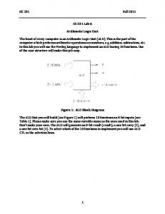
2. Interval ALU 2.1. Overall ALU Design Consider the intervals X = [xL , xU ] and Y = [yL , yU ]. The ALU is designed to perform operations Z = X op Y = {x op y | x ∈ X, y ∈ Y} where op ∈ {+, −, x, /}. It is also designed to perform the set operations of union, ∪ and intersection, ∩. As is typical with digital signal processors, only division by powers of 2 is implemented. That is, given X / Y , Y is degenerate and a power of two. This allows for the division operation to be achieved by simply shifting the bits of the numerator, X. The ALU is also capable of calculating the dot product of two vectors by a multiply-accumulate operation. In general, the result of each operation is a single interval. However, there is one situation where two intervals may result. This is the case when the union of two disjoint intervals is desired. Consider the operation X ∪ Y where X and Y are disjoint intervals. The result will then be two intervals, X and Y , and they will be placed on the output lines in two successive clock cycles. The ALU is a fixed-point unit which represents numbers in two’s complement format. One bit, the leftmost and most significant bit (MSB), is used as the sign bit. The remaining bits are used to represent the number. Figure ?? shows the structure of an N -bit signed number in two’s complement format as used in our implementation. Table ?? lists the inputs to the ALU. Operands are specified as 16-bit numbers. The ALU has input lines that allow selection of the multiply-accumulate mode and the number of bits for the
REC 2006 - William Edmonson
3
Interval ALU for Signal Processing and Control 1
N -1
sign
0
fraction
Figure 1. Fixed-point twos complement number format
output, rctl. The ALU has two 24-bit output lines for specifying the lower and upper bounds of the resulting interval. Table ?? shows the details of the output lines. Table I. Description of ALU Inputs Input
Description
Bit Width
xL xU yL yU cmd acc select rctl
Lower bound on left-hand operand Upper bound on left-hand operand Lower bound on right-hand operand Upper bound on right-hand operand Mathematical operation to be performed Perform multiply-accumulate when asserted Width of output results (Choice of 16- or 24-bits)
16 bits 16 bits 16 bits 16 bits 3 bits 1 bit 2 bits
Table II. Details of ALU outputs Output
Description
Bit Width
zL zU
Lower bound on result Upper bound on result
24 bits 24 bits
The hardware model is divided into three parts, namely, the flag generator, lower bound and upper bound modules. Figure ?? shows a schematic of the ALU. The flag generator module is responsible for generating flags that are used during multiplication. The nature of the input operands (xL , xU , yL , yU ) and their values relative to zero are used to determine the value of the flag. There are nine possible cases that need to be identified. The 4-bit mul flag is used to distinguish between these possible cases. Table ?? shows the nine cases of multiplication and the associated mul flag values. The flag produced by the flag generator module is used by the lower and upper bound modules to determine the appropriate output values when multiplication is the operation desired. Note that there is one case where the result is the union of two intervals. This is the case where both X and Y contain 0 (mul = 0000). We shall refer to this case as special case multiplication. The lower and upper bound modules are independent but equivalent in operation. These units are used for calculating the lower and upper bounds on the resulting interval(s). Both modules take the same set of inputs, namely the operands, mul flag and the command, cmd. Figure ?? shows the
REC 2006 - William Edmonson
4
William Edmonson xL xU yL yU cmd
16 16 16
Flag Generator
mul 4
16 3
Lower Bound Module
c
L
32
acc_select Rounding Unit
24
zL
24
zU
cU
Upper Bound Module
rctl
32
2
Figure 2. Schematic of Interval ALU
schematic for the lower and upper bound modules. Each module has an adder, a subtraction unit and a multiplier for performing computations, together with units of set operations.
Table III. Various cases of multiplication and associated mul flag values MUL
Case
X*Y
0001
xL ≥ 0; yL ≥ 0
[xL yL , xU yU ]
0010
yL ≥ 0; yL < 0 < yU
[xU yL , xU yU ]
0011
yL ≥ 0; yU ≤ 0
[xU yL , yL yU ]
0100
yL < 0 < xU ; yL ≥ 0
[yL yU , xU yU ]
0101
yL < 0 < xU ; yU ≤ 0
[xU yL , yL yL ]
0110
xU ≤ 0; yL ≥ 0
[yL yU , xU yL ]
0111
xU ≤ 0; yL < 0 < yU
[yL yU , yL yL ]
1000
xU ≤ 0; yU ≤ 0
[xU yU , yL yU ]
0000
yL < 0 < xU ;yL < 0 < yU
[min(xU yL , yL yU ), max(yL yL , xU yU )]
REC 2006 - William Edmonson
5
Interval ALU for Signal Processing and Control
Note that cout is equal to cL or cU for the lower bound and upper bound modules respectively. A register is used to latch the output of each module. add_res
16 16
yL
16
yU
16
sub_res
Addition, Multiplication mult_res & Set Operations u_res
MUX
xL xU
Delay
int_res
compare
cmd
MUX
Special Case Multiplication
c
in
c MAC
32
out
32
3
mul 4
acc_select
Figure 3. Block diagram of lower and upper bound modules
It is important to note that a delay unit is needed for special case multiplications. A comparator is also needed to perform the min and max operations. The presence of the delay unit implies that special case multiplications require an extra clock cycle to produce the final result. This is in contrast to the other arithmetic and set operations, namely, addition, subtraction, division, union and intersection, where the final result is obtained after one clock cycle. 2.2. Multiply Accumulate (MAC) Unit A dedicated multiply-accumulate functional unit is present in each of the lower and upper bound modules to execute the MAC instruction efficiently. An external input line acc select is provided to determine when the accumulation needs to be performed. When this input line is held high, the accumulator is in accumulate mode; otherwise it serves the purpose of a simple latch. Figure ?? shows the block diagram of the accumulator. Delay 0 Delay
compare
MUX acc_select
c in
32
+
Delay 32
c out
Figure 4. Multiply Accumulate (MAC) Unit
REC 2006 - William Edmonson
6
William Edmonson
2.3. Rounding Unit One of the requirements of the I-ALU is that it should provide accurate, reliable results. Roundoff errors occur naturally in binary computations because floating-point and fixed-point number systems are unable to represent every possible number. In situations where the true result is not exactly representable, it is typical to round the number to the nearest machine-representable number (?). However, this introduces errors. To avoid such errors, care must be taken to ensure that the resulting interval is guaranteed to contain the true result. This is achieved by using outward rounding. Outward rounding on an interval X = [xL , xU ] is achieved by rounding the lower bound, xL , to the largest machine representable number smaller than xL , and the upper bound xU , to the smallest machine-representable number larger than xU . This ensures that the true is result is contained in the resulting interval. The I-ALU accepts 16-bit inputs and thus, the largest possible output (obtained through multiplication) requires 32-bits. However, if desired, the ALU can provide 16-bit or 24-bit results. Obviously, simple truncation of the original 32-bit result will lead to errors. Rounding is therefore required in such situations. In twos complement number representation which is what is used for the ALU, the most significant bit of the result determines the sign of the answer. Different rounding modes need to be applied based on this sign of the output and also, based on whether the output value is to be rounded up or down. The bits of lower significance in the output have to be rounded up or down depending on the module under consideration. 2.3.1. Rounding Algorithm for Lower Bound Module The output of the lower bound module will always be rounded toward negative infinity. The bits of lower significance simply need to be discarded based on the total number of bits to be retained. Figure ?? illustrates the rounding algorithm for the lower bound module. MSB c
L
LSB 16-bit
8-bit
16-bit
8-bit
8-bit
32
16-bit
rctl
2 16/24
zL
Figure 5. Rounding Unit for Lower Bound Module
REC 2006 - William Edmonson
7
Interval ALU for Signal Processing and Control
2.3.2. Rounding Algorithm for Upper Bound Module Rounding for the output is slightly more complicated. If any of the bits that are to be discarded is a 1, a 1 is added to the part that is going to be retained after rounding. Otherwise, simple truncation is performed. Figure ?? illustrates this rounding algorithm in brief. MSB cU
rctl
LSB 16-bit
8-bit
8-bit
32
2
+
1 16/24
zU
Figure 6. Rounding Unit for Upper Bound Module
3. Performance & Results The I-ALU presented in this paper was designed in such a way that its performance would compare with non-interval ALUs. The two performance metrics of interest are throughput and area. Throughput was the more important performance metric so the design was first optimized for throughput and then for area. In other words, throughput was maximized while area was minimized. The design was implemented using Verilog HDL and synthesized using Synopsys. The 0.18µm technology library was used. In order to compare favorably with non-interval ALUs, an interval ALU should be able to produce the results of computations in a single clock cycle. The design presented produces results in one clock cycle, except for cases where the result is a union of two disjoint intervals. The fastest clock obtained for the design was 45.8MHz. Once the design was optimized for throughput, it was then optimized for area. The goal was to minimize the area. The minimum area obtained for our design was 218,569 µm2 .
REC 2006 - William Edmonson
8
William Edmonson
4. Conclusion We have presented in this paper a design for an Interval based Arithmetic Logic Unit having computational efficiency comparable to many present day digital signal processors. This ALU operates on intervals represented by fixed point numbers in twos complement form. To make the ALU specific to DSP and control applications, dedicated hardware with a reduced instruction set of addition, subtraction, multiplication and for filtering operations, the multiply-accumulate operator is implemented. To bind the errors that accrue due to rounding, the outward rounding has been implemented. Throughput and area of the design has been optimized to obtain the best results.
References Hansen, E., Global Optimization Using Interval Analysis. Marcel Dekker, Inc., 1992. Kulisch, U., Advanced Arithmetic for the Digital Computer. New York: Springer-Verlag, 2002. Schulte, M. and J. E. Swartzlander, A Family of Variable-Precision Interval Arithmetic Processors, IEEE Trans. Comput., vol. 49, no. 5, pp. 387–397, May 2000. Kuo. S. M. and W.-S. Gan, Digital Signal Processors: Architectures, Implementations and Applications. Prentice Hall, 2004. ANSI/IEEE, IEEE Standard for Binary Floating-Point Arithmetic. New York: ANSI/IEEE Std 754-1985, 1985. Moore, R. E. Interval Analysis. Prentice-Hall, Inc., 1966.
REC 2006 - William Edmonson