Modeling & Simulating. ASIC Designs with VHDL. Reference: Application
Specific Integrated Circuits. M. J. S. Smith, Addison-Wesley, 1997 Chapters 10 &
12.
Modeling & Simulating ASIC Designs with VHDL Reference: Application Specific Integrated Circuits M. J. S. Smith, Addison-Wesley, 1997 Chapters 10 & 12 Online version: http://www10.edacafe.com/book/ASIC/ASICs.php VHDL resources from other courses: ELEC 4200: http://www.eng.auburn.edu/~strouce/elec4200.html ELEC 5250/6250: http://www.eng.auburn.edu/~nelsovp/courses/elec5250_6250/
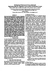
Digital ASIC Design Flow ELEC 5200/6200 Design Activity
Behavioral Model
Verify Function
VHDL/Verilog
Front-End Design
Synthesis DFT/BIST & ATPG
Gate-Level Netlist Full-custom IC
Test vectors Standard Cell IC & FPGA/CPLD DRC & LVS Verification
Verify Function
Transistor-Level Netlist Physical Layout
Map/Place/Route
Verify Function & Timing Back-End Design Verify Timing
IC Mask Data/FPGA Configuration File
ASIC CAD tools available in ECE
Modeling and Simulation
Design Synthesis (digital)
Design Architect-IC (Mentor Graphics) Design Framework II (DFII) - Composer (Cadence)
Physical Layout
Tessent DFT Advisor, Fastscan, SoCScan (Mentor Graphics)
Schematic Capture & Design Integration
Leonardo Spectrum (Mentor Graphics) Design Compiler (Synopsys), RTL Compiler (Cadence) FPGA: Xilinx ISE; CPLD: Altera Quartus II
Design for Test and Automatic Test Pattern Generation
Active-HDL (Aldec) Questa ADMS = Questa+Modelsim+Eldo+ADiT (Mentor Graphics) Verilog-XL, NC_Verilog, Spectre (Cadence)
IC Station (Mentor Graphics) SOC Encounter, Virtuoso (Cadence) Xilinx ISE/Altera Quartus II – FPGA/CPLD Synthesis, Map, Place & Route
Design Verification
Calibre DRC, LVS, PEX (Mentor Graphics) Diva, Assura (Cadence)
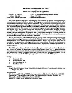
Questa ADMS
Analog, Digital, Mixed-Signal Simulation VHDL,Verilog, VHDL-AMS, Verilog-AMS, SPICE Netlists Working Library
Simulation Setup
Eldo, Eldo RF Analog (SPICE)
ADiT
Design_1 Design_2
VITAL
SPICE Xilinx models SIMPRIMS
IEEE 1164
Questa ADMS
EZwave View Results
Module Generators
Resource Libraries
Input Stimuli
Modelsim Digital (VHDL,Verilog)
Mixed Signal (VHDL-AMS, Verilog-AMS)
Hardware Description Languages
VHDL = VHSIC Hardware Description Language (VHSIC = Very High Speed Integrated Circuits)
Developed by DOD from 1983 – based on ADA IEEE Standard 1076-1987/1993/2002/2008 Based on the ADA language
Verilog – created in 1984 by Philip Moorby of Gateway Design Automation (merged with Cadence)
IEEE Standard 1364-1995/2001/2005 Based on the C language IEEE P1800 “System Verilog” in voting stage & will be merged with 1364
Other VHDL Standards
1076.1–1999:VHDL-AMS (Analog & Mixed-Signal Extensions) 1076.2–1996: Std.VHDL Mathematics Packages 1076.3-1997: Std.VHDL Synthesis Packages 1076.4-1995: Std.VITAL Modeling Specification (VHDL Initiative Towards ASIC Libraries) 1076.6-1999: Std. for VHDL Register Transfer Level (RTL) Synthesis 1164-1993: Std. Multivalue Logic System for VHDL Model Interoperability
HDLs in Digital System Design
Model and document digital systems
Hierarchical models System, RTL (Register Transfer Level), Gates Different levels of abstraction Behavior, structure
Verify circuit/system design via simulation Automated synthesis of circuits from HDL models
using a technology library output is primitive cell-level netlist (gates, flip flops, etc.)
Anatomy of a VHDL model
“Entity” describes the external view of a component “Architecture” describes the internal behavior and/or structure of the component
Example: 1-bit full adder A
Full Adder Sum
B Cin
Cout
Example: 1-Bit Full Adder entity full_add1 is port ( a: in bit; b: in bit; cin: in bit; sum: out bit; cout: out bit); end full_add1 ;
-- I/O ports -- addend input -- augend input -- carry input -- sum output -- carry output
I/O Port Declarations
Comments follow double-dash Type of signal Signal name
Signal direction (mode)
Port Format: name: direction data_type;
Direction in - driven into the entity from an external source (can read, but not update within architecture) out - driven from within the entity (can drive but not read within architecture) inout – bidirectional; drivers both within the entity and external (can read or write within architecture) buffer – like “out” but can read and write Data_type: any scalar or aggregate signal type
8-bit adder - entity -- Interconnect 8 1-bit adders for 8-bit adder entity Adder8 is port (A, B: in BIT_VECTOR(7 downto 0); Cin: in BIT; Cout: out BIT; Sum: out BIT_VECTOR(7 downto 0)); end Adder8;
Built-in Data Types
Scalar (single-value) signal types:
bit – values are ‘0’ or ‘1’ boolean – values are TRUE and FALSE integer - values [-231 … +(231-1)] on 32-bit host
Aggregate (multi-value) signal types:
bit_vector – array of bits
signal b: bit_vector(7 downto 0); signal c: bit_vector(0 to 7); b