1030
IEEE TRANSACTIONS ON ELECTRON DEVICES, VOL. 53, NO. 5, MAY 2006
Performance Enhancement of Partially and Fully Depleted Strained-SOI MOSFETs Toshinori Numata, Member, IEEE, Toshifumi Irisawa, Tsutomu Tezuka, Junji Koga, Norio Hirashita, Koji Usuda, Eiji Toyoda, Yoshiji Miyamura, Akihito Tanabe, Naoharu Sugiyama, and Shin-ichi Takagi, Member, IEEE
Abstract—The authors have developed short-channel strained-silicon-on-insulator (strained-SOI) MOSFETs on silicon– germanium (SiGe)-on-insulator (SGOI) substrates fabricated by the Ge condensation technique. 35-nm-gate-length strainedSOI MOSFETs were successfully fabricated. The strain in Si channel is still maintained for the gate length of 35 nm. The performance enhancement of over 15% was obtained in 70-nm-gatelength strained-SOI n-MOSFETs. Fully depleted strained-SOI MOSFETs with back gate were successfully fabricated on SGOI substrate with SiGe layers as thin as 25 nm. The back-gate bias control successfully operated and the higher current drive was obtained by a combination of the low doping channel and the back-gate control. Index Terms—MOSFETs, silicon–germanium (SiGe), siliconon-insulator (SOI), strained-silicon (strained-Si).
I. INTRODUCTION
S
TRAINED-SILICON (strained-Si) channels have been recognized as an indispensable technology for the mobility enhancement in advanced CMOS devices. Thus, several types of stress engineering have been proposed and demonstrated, including global or local stress and uniaxial or biaxial stress. Among them, strained-Si films epitaxially grown on relaxed silicon–germanium (SiGe) layers allow the provision of the global, biaxial, uniform, and large stress, which is expected to lead to significant performance enhancement and high immunity for process variations [1], [2]. However, there are several problems in bulk strained-Si MOSFETs on thick relaxed SiGe and SiGe graded-buffer layers deposited on Si substrates. One is the lower threshold voltage in n-MOSFETs due to the offset of the conduction band [3], [4]. When the threshold voltage of bulk strained-Si MOSFETs is adjusted to the same value as that of unstrained-Si devices, higher channel doping is needed, leading to the mobility reduction due to higher coulomb-scattering Manuscript received June 30, 2005; revised November 28, 2005. This work was supported by the New Energy and Industrial Technology Development Organization (NEDO). The review of this paper was arranged by Editor J. Wesler. T. Numata, T. Irisawa, T. Tezuka, J. Koga, N. Hirashita, K. Usuda, A. Tanabe, and N. Sugiyama are with the Millennium Research for Advanced Information Technology, Association of Super-Advanced Electronics Technology (MIRAI-ASET), Kawasaki 212-8582, Japan (e-mail:
[email protected]). E. Toyoda is with the Toshiba Ceramics Company, Ltd., Kawasaki 212-8582, Japan. Y. Miyamura is with the Komatsu Electronic Metals Company, Ltd., Kawasaki 212-8582, Japan. S. Takagi is with the MIRAI-AIST, National Institute of Advanced Industrial Science and Technology, Kawasaki 212-8582, Japan, and The University of Tokyo, Tokyo 113-8656, Japan. Digital Object Identifier 10.1109/TED.2006.871871
Fig. 1.
Device structure of strained-SOI MOSFET.
rate and higher effective field. Another problem is the worse short-channel effect due to the enhanced diffusion of arsenic and phosphorus in SiGe layers and resulting deeper junction depth [5]. Strained-SOI devices, on the other hand, are expected to solve these critical problems. Fig. 1 illustrates our target device structure for strained-SOI MOSFETs [6]. Thin strained-Si and SiGe layers are formed on buried oxides and the back-gate bias can be applied to supporting Si substrates. In fully depleted (FD) SOI with intrinsic channels, the threshold voltage can be adjusted by the gate work function control and/or the back-gate control [4], [7]. An intrinsic channel leads to maximizing the mobility enhancement and to reducing the threshold-voltage fluctuation due to the SOI thickness variation because of the negligibly small space charges [7]–[10]. Also, the thresholdvoltage control by using the back-gate bias allows the dynamic change in the threshold voltage, leading to a flexible device design and performance improvement, such as the increase in Ion –Ioff ratio and the applicability of single metal gate technology. In addition, short-channel effects can be improved in such ultrathin body strained-SOI MOSFETs because the junction depth is determined by the physical thickness of the thin SOI films. With regard to MOSFETs using the global-strain substrates, however, it is still unclear whether the performance enhancement can be obtained in ultrashort gate length. It is necessary to clarify the physical origins of the dependence of the performance enhancement on the gate length in strained-SOI MOSFETs. It is also necessary to confirm the further improvement by FD strained-SOI MOSFETs with intrinsic channel. We focus on strained-SOI MOSFETs using SiGe-oninsulator (SGOI) substrates in this paper. This paper presents the successful fabrication of partially depleted (PD) and fully depleted (FD) strained-SOI MOSFETs and the performance
0018-9383/$20.00 © 2006 IEEE
NUMATA et al.: PERFORMANCE ENHANCEMENT OF PARTIALLY AND FD STRAINED-SOI MOSFETs
1031
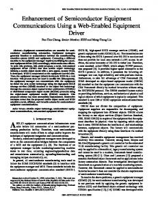
Fig. 3. Cross-sectional TEM image of strained-SOI substrate. TABLE I TYPICAL CHARACTERISTICS OF STRAINED-SOI WAFERS
Fig. 2.
Typical process flow of strained-SOI substrates.
enhancement of strained-SOI MOSFETs in the sub-100-nm region. The dependence of the performance enhancement on the channel length is also examined in greater detail than in the previous proceeding [11]. The possibility of further increase in the performance is examined by using the FD strained-SOI MOSFETs with back gate. The organization of this paper is as follows. The fabrication of strained-SOI wafers and MOSFETs is shown in Section II. Then, in Section III, the performance enhancement and the dependence of the performance enhancement on the channel length are presented in the case of using PD strained-SOI MOSFETs. Next, the increase in the performance of FD strained-SOI MOSFETs is demonstrated in Section IV. Finally, conclusions are drawn in Section V. II. FABRICATION OF STRAINED-SOI WAFERS AND MOSFETS The fabrication of high-quality strained-Si wafers is one of the most important issues concerning strained-Si devices using the global strain. SGOI wafers used for strained-SOI substrates were fabricated by the Ge-condensation technique [12]. Fig. 2 shows the typical process flow of strained-SOI substrates. SiGe films are grown on conventional SOI substrates and oxidized at high temperature. The main idea of the Ge-condensation technique is the rejection of Ge atoms from thermal oxides and the blocking of the Ge diffusion toward Si substrates by buried oxides. As a result, Ge content in remaining SiGe films becomes higher as the oxidation proceeds. Also, relaxation of SiGe films is obtained during this high-temperature oxidation. After removing surface silicon dioxides, strained-Si films are epitaxially grown on the SGOI substrates. Two hundred-millimeter-diameter strained-SOI wafers were successfully fabricated [13]. Fig. 3 shows a cross-sectional TEM image of a strained-SOI substrate. A smooth interface between SiGe and the buried oxide layer and a smooth surface of the strained-Si layer are observed. Table I shows the typical characteristics of strained-SOI wafers used in the present study.
The total strained-SOI thickness of both strained-Si and SiGe layers was taken to be 108 nm for PD strained-SOI MOSFETs. The amount of strain was around 1.0%, corresponding to the effective Ge content of relaxed SiGe layer of around 24%. The uniformity of strain in Si and the effective Ge content over the whole wafers were within 3% in terms of relative standard deviation. The small surface roughness of < 0.5-nm rms, evaluated in the 10 µm square surface by atomic force microscopy (AFM), was obtained without chemical mechanical polishing (CMP) processes. Also, thinning of SiGe layers is one of the most important issues from the viewpoint of scalability. We have fabricated thin strained-SOI substrates by an SiGe thinning technique through oxidation without Ge condensation [14]. The SiGe layers were thinned from 84 to 25 nm by this technique. Raman spectra confirmed that the strain of strained-Si layers was almost preserved even through this thinning process. The wafer surface roughness of the ultrathin strained-SOI wafers was < 1.0 nm rms for the 10 µm square surface by AFM. The buried oxide thickness was 145 nm. Silicon oxynitride (SiON) gate insulators with the physical thickness of 1.6 nm and nickel salicide processes were used for fabrication of MOSFETs on these strained-SOI substrates. Fig. 4(a) and (b) shows the cross-sectional TEM images of fabricated strained-SOI MOSFETs with the total strained-SOI thickness of 102 and 39 nm. The strained-SOI MOSFETs with the gate length down to around 35 nm were successfully fabricated. In PD strained-SOI MOSFETs [Fig. 4(a)], higher channel impurity concentration was doped in strained-SOI than that in conventional SOI in order to adjust the threshold voltage, whereas the extension and halo were formed under the same condition for strained-SOI and conventional SOI devices. Also, in FD strained-SOI MOSFETs [Fig. 4(b)], the Si substrates under the buried oxides were doped by ion implantation through strained-SOI wafer in order to form the back-gate electrode. The species for the back-gate implantation was boron and the dose was set to be 1 × 1017 cm−3 , to preserve the crystal quality and the channel doping concentration of strainedSi/SiGe layers and to control the threshold voltage sufficiently with the back-gate biasing [15]. Local strain technique by
1032
IEEE TRANSACTIONS ON ELECTRON DEVICES, VOL. 53, NO. 5, MAY 2006
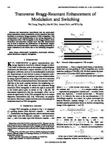
Fig. 6. (a) Id –Vg curves of strained-SOI (closed circles) and conventionalSOI (open circles) nMOSFETs with the gate length of 70 nm and (b) threshold-voltage rolloff characteristics of strained-SOI (closed circles) and conventional-SOI (open circles) nMOSFETs.
Fig. 4. Cross-sectional TEM images of (a) 36-nm-gate-length PD strainedSOI MOSFET on strained-SOI substrate (TsSi/TSiGe = 18/84 nm) and (b) 32-nm-gate-length FD strained-SOI MOSFETs on thin SGOI substrate (TsSi/TSiGe = 14/25 nm).
Fig. 5. Electron and hole mobility in strained-SOI (closed circles and closed triangles) and conventional-SOI (open circles and open triangles) MOSFETs; Lg/Wg = 10/10 µm.
shallow trench isolation (STI) and Si nitride capping layer were not applied in this study. III. PERFORMANCE ENHANCEMENTS IN PD STRAINED-SOI MOSFETS The performance enhancement of PD strained-SOI MOSFETs is described in this section. Fig. 5 shows the
electron and hole mobilities of strained-SOI and conventional SOI MOSFETs with long gate lengths. The electron mobility enhancement of 1.8 is obtained. This mobility enhancement is in good agreement with that in the previous report [16]. The hole mobility of strained-SOI, on the other hand, is similar to that of the conventional SOI, because of the relatively low effective strain and the high effective field due to high channel doping. Fig. 6(a) shows the Id –Vg characteristics with the gate length of 70 nm. Good cutoff characteristics similar to those of the conventional SOI are obtained for strained SOI. Fig. 6(b) shows the threshold-voltage rolloff characteristics of strained-SOI and conventional SOI n-MOSFETs. The threshold-voltage rolloff of thick strained-SOI is almost the same as that of conventional SOI, down to the gate length of around 70 nm. In shorter gate lengths, however, the short-channel effects of strained-SOI n-MOSFETs are found to be worse even with higher channel doping than conventional SOI. This is due to the enhanced arsenic diffusion in the SiGe layers, which is similar to the case of bulk strained-Si MOSFETs. Fig. 7 shows the Id –Vd characteristics of a strained-SOI n-MOSFET with the gate length of 70 nm. Id –Vd characteristics are measured as a function of the gate-drive voltage under the dc measurement. The edge of the active area forms free surface that causes the relaxation of strained-Si [17], [18]. In this paper, however, the gate width is set to be 1 µm, which is large enough to eliminate the effect of the relaxation of strained-Si. The drain current of the strainedSOI device increases by around 15% at the same gate drive. Fig. 8(a) shows the Ion –Ioff characteristics. The performance
NUMATA et al.: PERFORMANCE ENHANCEMENT OF PARTIALLY AND FD STRAINED-SOI MOSFETs
1033
Fig. 7. Id –Vg characteristics of strained-SOI (solid lines) and conventionalSOI (dashed lines) nMOSFETs, Lg = 70 nm and Wg = 1 µm.
Fig. 9. (a) Transconductance of strained-SOI (closed circles) and conventional-SOI (open circles) nMOSFET in short-channel region. (b) Gatelength dependence of transconductance, gm, enhancement. gm was measured at the drain voltage of 50 mV. The value of gm is the maximum for the gate voltage.
Fig. 8. (a) Ion –Ioff characteristics of strained-SOI (closed circles) and conventional-SOI (open circles) nMOSFETs and (b) Id –Vd characteristics of strained-SOI and conventional-SOI nMOSFETs in static and pulsed measurements. Gate length is taken to be 0.15 µm.
enhancement based on the dc measurement is around 7% at the same Ioff . It is known, however, that the drain current of SOI MOSFETs in dc operation decreases because of the self-heating effect, where SOI devices are thermally insulated by buried oxide, and that low thermal conductivity in SiGe also causes a similar self-heating effect [1], [19]. Fig. 8(b) shows the pulsed-IV measurements of strained-SOI and conventional SOI devices [20]. The drain-current enhancement of 18% under ac measurement over static measurements was observed in strained-SOI devices, whereas the enhancement was 11% in conventional SOI devices. These results mean that the performance boost of an additional 7% can be obtained under the real ac device operation because ac measurement observes the drain current where the channel mobility is not decreased by heat. As
a result, the overall performance enhancement of strained-SOI against the conventional SOI is estimated to be around 14% under real large scale integration (LSI) operation. The preservation of the performance enhancement in short gate lengths is one of the most critical issues for realizing LSIs using strained-Si devices on the global-strain substrates. Fig. 9(a) shows the gate-length dependence of transconductance of strained-SOI and conventional SOI n-MOSFETs in short gate region, and Fig. 9(b) shows the gate-length dependence of transconductance enhancement of strainedSOI n-MOSFETs compared with that of conventional SOI n-MOSFETs. It is found that the transconductance enhancement decreases with a decrease in the gate length. While the transconductance enhancement of around 10% is still maintained at the gate length of 70 nm, it is almost zero at the gate length of around 45 nm. A possible origin of the decrease in the transconductance is the relaxation of strain in the channels, particularly near source and drain region [21]. Thus, in order to examine whether the strain in the strained-Si channels is still maintained in the shortchannel region, the strain distribution in the Si channels of the gate length of 35 nm was measured by nanobeam electron diffraction (NBD) [22]. Fig. 10(a) shows the measurement points of NBD in strained-SOI MOSFETs with the gate length of 35 nm. Since the resolution of measurement determined by a spot size of electron beam is around 10 nm, this NBD method allowed us to measure the distribution of the strain in the channel Si layer with a thickness of 18 nm in this
1034
IEEE TRANSACTIONS ON ELECTRON DEVICES, VOL. 53, NO. 5, MAY 2006
Fig. 12. Contact resistance between nickel salicide and N+ region of conventional SOI (SOI), strained-SOI (SGOI), and strained-SOI with elevated Si layer (SGOI_Elev). Thickness of elevated Si layer is taken to be 20 nm.
Fig. 10. NBD results of strain in Si. (a) Measurement points of NBD for strained-SOI MOSFETs with the gate length of 35 nm. Circles in TEM image denote measurement points and size of incident electron beam of NBD. (b) Strain in channel Si layer along the horizontal and vertical directions.
Fig. 11. Gate-length dependence of enhancement factor. Solid curve with closed circles shows the measurement result and dashed curve shows the calculated result, where parasitic resistances of strained-SOI and conventional SOI MOSFETs were 300 and 100 Ω · µm, respectively, simply measured through the gate-length dependence of device resistance, changing gate voltages. Dotted curve shows the calculated result of the performance enhancement where the parasitic resistance of strained-SOI MOSFETs is taken to be the same as that of the conventional-SOI devices, which is 100 Ω · µm.
study. Fig. 10(b) shows the amount of strain of Si along the horizontal and vertical directions. NBD can evaluate lattice variation because lattice spacing in strained-Si layer is detected by relative comparison with the diffraction pattern of standard Si for which the Si substrate under buried oxide is used in this study. When compared with the strain in Si of the long gate length, which is on the same substrate as the short gate length, it is found that the strain in the Si channel with the gate length of 35 nm is almost the same as that in the devices with the long gate length, meaning that the strain in channel Si layers is still maintained even in the case of the short gate length. Previous work has reported that the typical source/drain
techniques may form free surfaces that would cause relaxation [21]. The relaxation of strained-Si layer might vary according to the process conditions, such as the gate oxide thickness and the gate reactive ion etching (RIE) conditions, including the type of wafer, that is, bulk strained-Si wafer or strained-SOI wafer. Next, the parasitic and the channel resistances were evaluated in order to clarify the reason for the lowering of the performance enhancement in strained-SOI devices in the short gate length. The parasitic resistance was simply measured through the gate-length dependence of the total resistance of MOSFETs changing gate voltages. As a result, the parasitic resistance of strained SOI was around 300 Ω · µm, which is three times higher than that of the conventional SOI, which is 100 Ω · µm. Based on these values, the gate-length dependence of the enhancement factor was calculated. The results are shown in Fig. 11. The solid curve with closed circles shows the measurement result, which is obtained from the comparison of the drain current in the gate-drive voltage (Vg –Vth ) of 0.8 V and the drain voltage of 50 mV, and the dashed curve shows the calculated result. The good agreement of both curves strongly suggests that the decrease in the performance enhancement in shorter gate length is attributable to the higher parasitic resistance in strained SOI n-MOSFETs. Also, the dotted curve in Fig. 11 shows the calculated result of the performance enhancement with the same parasitic resistance of conventional SOI n-MOSFETs. It is confirmed that, when the parasitic resistance is reduced to the same level as the conventional ones, the draincurrent enhancement higher than 1.2 can be obtained at the gate length shorter than 40 nm. However, the effect of high channel doping for the threshold-voltage adjustment, which decreases the mobility enhancement due to the high coulomb scattering and the high effective field, is still applied irrespective of the parasitic resistance. As a result, the reduction of the parasitic resistance is a key issue for obtaining high performance enhancement in the short gate lengths. While quantitative assignment of the parasitic resistance in MOSFETs has not been clarified yet, one possible reason for this higher parasitic resistance in strained-SOI MOSFETs is the high contact resistance between nickel salicide and N+ source/drain region. Fig. 12 shows the comparison of the contact resistance between the strained-SOI and conventional-SOI devices. The
NUMATA et al.: PERFORMANCE ENHANCEMENT OF PARTIALLY AND FD STRAINED-SOI MOSFETs
1035
Fig. 13. Threshold-voltage rolloff characteristics of strained-SOI (open circles) and thin strained-SOI (closed circles) nMOSFETs. Channel doping conditions are the same.
contact resistance in the strained-SOI n-MOSFETs is larger than that in the conventional SOI n-MOSFETs, suggesting that higher contact resistance, presumably related to SiGe, such as the formation of nickel germanide, is responsible for the higher parasitic resistance and the resulting decrease of the draincurrent enhancement in short gate lengths. One possible way of reducing the parasitic resistance is to apply the elevated source/drain structure. Actually, as shown in Fig. 12, we have confirmed that the contact resistance between NiSi and n+ regions in the elevated Si layers on strained-Si films can be reduced to the value in conventional-SOI MOSFETs. In this study, strained-SOI devices with elevated S/D do not operate at a high drain current, because of the offset between the gate and the extension, leading to the high parasitic resistance. The parasitic resistance is composed of several resistances, such as the extension, the source/drain, and the contact resistance. The elevated source/drain structure contributes to the reduction of the contact resistance, leading to the decrease in the parasitic resistance. However, the parasitic resistance might still be higher than that of the SOI devices because junction profiles and activation energy are different due to the strained-Si/SiGe layers. IV. DEVICE CHARACTERISTICS OF FD STRAINED-SOI MOSFETS The device characteristics of FD strained-SOI MOSFETs are shown in this section. Thin strained-SOI substrates with thin SiGe layers are used for FD strained-SOI MOSFETs [Fig. 4(b)]. The strain of strained-Si layer on thin strained-SOI substrate is preserved even through SGOI thinning processes and device fabrication. The mobility enhancement obtained for thin strained-SOI devices is almost the same as that for thick strained-SOI devices. Fig. 13 shows the rolloff characteristics of strained-SOI and thin strained-SOI MOSFETs. It is found that short-channel effects of thin strained-SOI devices are slightly improved, suggesting that a thin body is effective in suppressing the short-channel effects in strained-SOI MOSFET as well [4]. Another interesting feature of FD strained-SOI MOSFETs is the possibility of the threshold-voltage control by the back gate. Fig. 14(a) shows the change in the threshold voltage as a function of the back-gate voltage. It is confirmed that the threshold voltage can be controlled by using the back-gate bias
Fig. 14. (a) Change in threshold voltage as a function of back-gate voltage. Solid curve shows results of device simulations. (b) Drain current of the strained-SOI MOSFETs with high (triangles) and low (circles) doping concentration as a function of threshold voltage adjusted by back-gate voltage. The drain voltage is set to be 50 mV.
in strained-SOI MOSFETs. The results of the device simulations are shown as solid curves in Fig. 14(a). The agreement with the measurement results suggests the existence of good interface properties between SiGe and buried oxide, although the slightly weaker back-gate voltage dependence of the experimental results is attributable to the interface states at the back interface. Fig. 14(b) shows the drain current of the strainedSOI MOSFETs with high and low doping concentration as a function of back-gate voltage. It is found that the drain current with the low-doped channel is higher than that with the highly doped channel at the same threshold voltage. This higher current with the low-doped channel is attributable to lower impurity scattering rate. On the other hand, higher impurity concentrations used in bulk/PD strained-Si n-MOSFETs for adjusting threshold voltage are known to significantly compensate the mobility enhancement. Thus, low-doped FD strainedSOI MOSFETs with the threshold voltage adjusted by the back-gate bias can maximize the benefit of strained-Si channels, where the mobility enhancement due to the elimination of channel doping is superposed on that due to the strain. V. CONCLUSION Strained-SOI MOSFETs with the gate length down to around 35 nm were successfully fabricated on SGOI substrates fabricated by the Ge-condensation technique. We investigated the performance enhancement of the strained-SOI MOSFETs in the sub-100-nm region and the possibility of further increase in the performance by using FD strained-SOI MOSFETs with
1036
IEEE TRANSACTIONS ON ELECTRON DEVICES, VOL. 53, NO. 5, MAY 2006
back gate. The drain current of a strained-SOI n-MOSFET with the gate length of 70 nm increases by around 15% for dc measurements. While the performance enhancement decreased with a decrease in the gate length, the strain in channel Si layers is maintained even in the case of the short gate length of 35 nm. The reduction of the parasitic resistance is a key issue for obtaining the high performance enhancement in the short gate lengths, and the elevated source/drain structure is a promising approach. Low-doped FD strained-SOI MOSFETs with the threshold voltage adjusted by the back-gate bias can maximize the benefit of strained-Si channels. These results indicate that strained-SOI n-MOSFETs still can obtain the performance enhancement under sub-50-nm regime. Since the performance of p-MOSFETs can also be improved by SGOI substrates with high Ge content and low channel doping [23], thin-body strained-SOI structure with global strain is still appropriate for high-performance CMOS devices. ACKNOWLEDGMENT The authors would like to thank T. Mizuno, T. Maeda, K. Ikeda, and K. Matsuzawa for the valuable discussion, and N. Fukushima, T. Kanayama, S. Kawamura, T. Masuhara, and M. Hirose for the support throughout this work. R EFERENCES [1] B. H. Lee, A. Mocuta, S. Bedell, H. Chen, D. Sadana, K. Rim, P. O’Neil, R. Mo, K. Chan, C. Cabral, C. Lavoie, D. Mocuta, A. Chakravarti, R. M. Mitchell, J. Mezzapelle, F. Jamin, M. Sendelbach, H. Kermel, M. Gribelyuk, A. Domenicucci, K. A. Jenkins, S. Narasimha, S. H. Ku, M. Ieong, I. Y. Yang, E. Leobandung, P. Agnello, W. Haensch, and J. Welser, “Performance enhancement on sub-70 nm strained silicon SOI MOSFETs on ultra-thin thermally mixed strained silicon/SiGe on insulator (TM-SGOI) substrate with raised S/D,” in IEDM Tech. Dig., 2002, pp. 946–948. [2] J. R. Hwang, J. H. Ho, S. M. Ting, T. P. Chen, Y. S. Hsieh, C. C. Huang, Y. Y. Chiang, H. K. Lee, L. Ariel, T. M. Shen, G. Braithwaite, M. Currie, N. Gerrish, R. Hammond, A. Lochtefeld, F. Singaporewala, M. Bulsara, Q. Xiang, M. R. Lin, W. T. Shiau, Y. T. Loh, J. K. Chen, S. C. Chien, and F. Wen, “Performance of 70 nm strained-silicon CMOS devices,” in VLSI Symp. Tech. Dig., 2003, pp. 103–104. [3] H. M. Nayfeh, J. L. Hoyt, and D. A. Antoniadis, “A physically based analytical model for the threshold voltage of strained-Si n-MOSFETs,” IEEE Trans. Electron Devices, vol. 51, no. 12, pp. 2069–2072, Dec. 2004. [4] T. Numata, T. Mizuno, T. Tezuka, J. Koga, and S. Takagi, “Control of threshold voltage and short channel effects in ultra-thin strained-SOI CMOS,” IEEE Trans. Electron Devices, vol. 52, no. 8, pp. 1780–1786, Aug. 2005. [5] S. Eguchi, J. L. Hoyt, C. W. Leitz, and E. A. Fitzgerald, “Comparison of arsenic and phosphorus diffusion behavior in silicon–germanium alloys,” Appl. Phys. Lett., vol. 80, no. 10, pp. 1743–1745, Mar. 2002. [6] S. Takagi, T. Mizuno, N. Sugiyama, T. Tezuka, and A. Kurobe, “StrainedSi-on-insulator (strained-SOI) MOSFETs—Concept, structures and device characteristics,” IEICE Trans. Electron., vol. E84-C, no. 8, pp. 1043–1050, 2001. [7] T. Numata and S. Takagi, “Device design for subthreshold slope and threshold voltage control in sub-100-nm fully depleted SOI MOSFETs,” IEEE Trans. Electron Devices, vol. 51, no. 12, pp. 2161–2167, Dec. 2004. [8] J. Chen, R. Solomon, T.-Y. Chan, P. K. Ko, and C. Hu, “Threshold voltage and C–V characteristics of SOI MOSFET’s related to Si film thickness variation on SIMOX wafers,” IEEE Trans. Electron Devices, vol. 39, no. 10, pp. 2346–2353, Oct. 1992. [9] E. Leobandung and S. Y. Chow, “Threshold voltage sensitivity of 0.1 µm channel length fully-depleted SOI NMOSFET’s with back-gate bias,” IEEE Trans. Electron Devices, vol. 42, no. 9, pp. 1707–1709, Sep. 1995. [10] T. Numata, M. Noguchi, and S. Takagi, “Reduction in threshold voltage fluctuation in fully-depleted SOI MOSFETs with back gate control,” Solid State Electron., vol. 48, no. 6, pp. 979–984, Jun. 2004.
[11] T. Numata, T. Irisawa, T. Tezuka, J. Koga, N. Hirashita, K. Usuda, E. Toyoda, Y. Miyamura, A. Tanabe, N. Sugiyama, and S. Takagi, “Performance enhancement of partially- and fully-depleted strained-SOI MOSFETs and characterization of strained-Si device parameters,” in IEDM Tech. Dig., 2004, pp. 177–180. [12] T. Tezuka, N. Sugiyama, S. Takagi, and T. Kawakubo, “Dislocation-free formation of relaxed SiGe-on-insulator layers,” Appl. Phys. Lett., vol. 80, no. 19, pp. 3560–3562, May 2002. [13] N. Hirashita, T. Numata, T. Tezuka, N. Sugiyama, K. Usuda, T. Irisawa, A. Tanabe, Y. Moriyama, S. Nakaharai, S. Takagi, E. Toyoda, and Y. Miyamura, “Strained-Si/SiGe-on-insulator wafers fabricated by Gecondensation process,” in Proc. IEEE Int. SOI Conf., 2004, pp. 141–142. [14] T. A. Langdo, A. Lochtefeld, M. T. Currie, R. Hammond, V. K. Yang, J. A. Carlin, C. J. Vineis, G. Braithwaite, H. Badawi, M. T. Bulsara, and E. A. Fitzgerald, “Preparation of novel SiGe-free strained Si on insulator substrates,” in Proc. IEEE Int. SOI Conf., 2002, pp. 211–212. [15] N. G. Tarr, Y. Wang, R. Soreefan, W. M. Snelgrove, B. M. Manning, S. Bazarjani, and T. W. MacElwee, “Limitations on threshold adjustment by backgating in fully depleted silicon-on-insulator metal-oxidesemiconductor field effect transistors,” J. Vac. Sci. Technol. A, Vac. Surf. Films, vol. 16, no. 2, pp. 838–842, Mar. 1998. [16] M. T. Currie, C. W. Leitz, T. A. Langdo, G. Taraschi, and A. Fitzgerald, “Carrier mobilities and process stability of strained Si n- and p-MOSFETs on SiGe virtual substrates,” J. Vac. Sci. Technol. B, Microelectron. Process. Phenom., vol. 19, no. 6, pp. 2268–2279, Nov. 2001. [17] S. M. Cea, M. Armstrong, C. Auth, T. Ghani, M. D. Giles, T. Hoffmann, R. Kotlyar, P. Matagne, K. Mistry, R. Nagisetty, B. Obradovic, R. Shaheed, L. Shifren, M. Stettler, S. Tyagi, X. Wang, C. Weber, and K. Zawadzki, “Front end stress modeling for advanced logic technologies,” in IEDM Tech. Dig., 2004, pp. 963–966. [18] T. Irisawa, T. Numata, T. Tezuka, K. Usuda, N. Hirashita, N. Sugiyama, E. Toyoda, and S. Takagi, “High current drive uniaxially-strained SGOI pMOSFETs fabricated by lateral strain relaxation technique,” in VLSI Symp. Tech. Dig., 2005, p. 10A-3. [19] K. Rim, J. Chu, H. Chen, K. A. Jenkins, T. Kanarsky, K. Lee, A. Mocuta, H. Zhu, R. Roy, J. Newbury, J. Ott, K. Petrarca, P. Mooney, D. Lacey, S. Koester, K. Chan, D. Boyd, M. Ieong, and H.-S. Won, “Characteristics and device design of sub-100 nm strained-Si n- and pMOSFETs,” in VLSI Symp. Tech. Dig., 2002, pp. 99–100. [20] K. A. Jenkins and J. Y.-C. Sun, “Measurement of I–V curves of siliconon-insulator (SOI) MOSFETs without self-heating,” IEEE Electron Device Lett., vol. 16, no. 4, pp. 139–141, Apr. 1995. [21] H. Kawasaki, K. Ohuchi, A. Oishi, O. Fujii, H. Tsujii, T. Ishida, K. Kasai, Y. Okayama, K. Kojima, K. Adachi, N. Aoki, T. Kanemura, D. Hagishima, M. Fujiwara, S. Inaba, K. Ishimaru, N. Nagashima, and H. Ishiuchi, “Impact of parasitic resistance and silicon layer thickness scaling for strained-silicon MOSFETs on relaxed Si1−x Gex virtual substrate,” in IEDM Tech. Dig., 2004, pp. 169–172. [22] K. Usuda, T. Numata, T. Tezuka, N. Sugiyama, Y. Moriyama, S. Nakaharai, and S. Takagi, “Strain evaluation for thin strained-Si on SGOI and strained-Si on nothing (SSON) structures using nanobeam electron diffraction (NBD),” in Proc. IEEE Int. SOI Conf., 2003, pp. 138–139. [23] T. Mizuno, N. Sugiyama, T. Tezuka, T. Numata, T. Maeda, and S. Takagi, “Design for scaled thin film strained-SOI CMOS devices with higher carrier mobility,” in IEDM Tech. Dig., 2002, pp. 31–34.
Toshinori Numata (M’99) was born in Osaka, Japan, in 1972. He received the B.S., M.S., and Ph.D. degrees in electronic engineering from Osaka University, Osaka, in 1995, 1997, and 2006, respectively. He has been with the Corporate Research and Development Center, Toshiba Corporation, Kawasaki, Japan, since 1997, where he has been engaged in the research and development of SOI devices and their technology. He has also been a member of the Millennium Research for Advanced Information Technology (MIRAI) Project, Association of SuperAdvanced Electronics Technology (ASET), since 2001, where he works on strained-Si technology. Dr. Numata is a member of the IEEE Electron Device Society and the Japan Society of Applied Physics.
NUMATA et al.: PERFORMANCE ENHANCEMENT OF PARTIALLY AND FD STRAINED-SOI MOSFETs
Toshifumi Irisawa was born in Tokyo, Japan, in 1975. He received the B.S., M.S., and Ph.D. degrees in applied physics from the University of Tokyo, Tokyo, in 1998, 2000, and 2003, respectively. His Ph.D. thesis concerned the study of growth and transport properties of Si/Ge heterostructures. He has joined the Toshiba Research and Development Center, Kawasaki, Japan, since 2003. He has been a member of Millennium Research for Advanced Information Technology (MIRAI) Project, Association of Super-Advanced Electronics Technology (ASET), since 2003, where he works on strained-Si, SiGe, and SOI CMOS. Dr. Irisawa is a member of the Japan Society of Applied Physics.
Tsutomu Tezuka was born in Japan, in 1964. He received the B.S. and M.S. degrees in physics from Tohoku University, Sendai, Japan, in 1987 and 1989, respectively. He has been with the Toshiba Research and Development Center, Kawasaki, Japan, since 1989, where he has been working on the research and development of semiconductor lasers and strained-SiGe/Si field-effect transistors. He is currently developing strained SOI (SGOI) MOSFETs. Currently, he is with the Millennium Research for Advanced Information Technology (MIRAI) Project, Association of Super-Advanced Electronics Technology (ASET), where he is now working on the strained-SOI and strained SGOI-CMOS devices. Mr. Tezuka won the Japan Society of Applied Physics Award for the Most Promising Young Scientist in 1994. He is a member of the Physical Society of Japan and the Japan Society of Applied Physics.
Junji Koga received the B.S. degree in physics from the University of Tokyo, Tokyo Japan, in 1988. He has joined the Research and Development Center of Toshiba Corporation, Kawasaki, Japan, since 1988, where he has been engaged in the research on the MOSFET device physics including thin-film SOI transistor, Cryo-CMOS device technology, and silicon functional tunnel device. He is now with the Advanced LSI Technology Laboratory of Toshiba Corporation. He has also been a member of Millennium Research for Advanced Information Technology (MIRAI) Project, Association of Super-Advanced Electronics Technology (ASET), since 2001, where he works on the strained-Si technology. Mr. Koga is a member of the Japan Society of Applied Physics.
Norio Hirashita received the B.S., M.S., and Ph.D. degrees in applied physics from University of Electro-Communications, Tokyo, Japan, in 1978, 1980, and 1996. He joined Oki Electric Industry Company, Ltd., Tokyo, in 1980, where he was engaged in the research and development of characterization of materials and fabrication processes of very large scale integration (VLSI) devices. He has also worked on the fabrication processes, including FD-SOI device and salicide technologies. He joined the Millennium Research for Advanced Information Technology (MIRAI) Project, Association of Super-Advanced Electronic Technology (ASET), since 2003, where he works on the strained-Si technology. Dr. Hirashita is a member of the Japan Society of Applied Physics.
1037
Koji Usuda was born in Tokyo, Japan, on September 14, 1959. He received the B.S. and M.S. degrees in applied physics from the University of ElectroCommunications, Tokyo, in 1983 and 1985, and the Ph.D degree in materials structure science from The Graduate University for Advanced Studies, Hayama, Japan, in 1995. He joined the Toshiba Research and Development Center, Kawasaki, Japan, in 1985, where he was engaged in the research and development on the GaAs and SiGe devices. He has also been a member of Millennium Research for Advanced Information Technology (MIRAI) Project, Association of SuperAdvanced Electronics Technology (ASET), since 2001, where he works on strained-Si devices and their characterization methods. Dr. Usuda is a member of the Japan Society of Applied Physics.
Eiji Toyoda was born in Japan, in 1975. He received the B.S. degree in engineer from Kogakuin University, Tokyo, Japan, in 1994, and the M.S. degrees in structural chemistry from Stockholm University, Stockholm, Sweden, in 2001. He has been with the Toshiba Ceramics, Tokyo, since 2001, where he has been working on the research and development of silicon and strained-Si wafers.
Yoshiji Miyamura received the B.S. and M.S. degrees in physics from Tohoku University, Sendai, Japan, in 1986 and 1988, respectively. He joined the Komatsu Electronic Metals Company, Ltd., Hiratsuka, Japan, in 1988, where he worked on research and development of silicon wafers. His current research interest is strained silicon.
Akihito Tanabe was born in Kanagawa, Japan, on March 22, 1964. He received the B.S. degree in applied physics and the M.S. degree in information processing from the Tokyo Institute of Technology, Tokyo, Japan, in 1986 and 1988, respectively. He joined the Microelectronics Research Laboratories, NEC Corporation, Sagamihara, Japan, in 1988, where he was engaged in the research and development of charge coupled devices (CCD) image sensors. From 1994 to 1995, he was a Visiting Scholar at the Pennsylvania State University, State College, PA, where he studied hydrogen-induced defects in crystalline silicon. After returning to the Silicon Systems Research Laboratories, he was engaged in the technology of CCD image sensors and MOSFETs. He has been a member of Millennium Research for Advanced Information Technology (MIRAI) Project, Association of Super-Advanced Electronics Technology (ASET), since 2002, where he has been working on strained-Si technology. Mr. Tanabe is a member of the Japan Society of Applied Physics.
1038
Naoharu Sugiyama was born in Shizuoka, Japan, in 1959. He received the B.S., M.S., and Ph.D. degrees in nuclear engineering from Nagoya University, Nagoya, Japan, in 1982, 1984, and 1993, respectively. In 1984, he joined the Toshiba Research and Development Center, Kawasaki, Japan. From 1987 to 1990, he was on leave at the Optoelectronics Technology Research Laboratory, Tsukuba, Japan. His research interest is the epitaxial growth of semiconductor thin films. Dr. Sugiyama is a member of the Japan Society of Applied Physics and the Vacuum Society of Japan.
IEEE TRANSACTIONS ON ELECTRON DEVICES, VOL. 53, NO. 5, MAY 2006
Shin-ichi Takagi (M’93) was born in Tokyo, Japan, on August 25, 1959. He received the B.S., M.S. and Ph.D. degrees in electronic engineering from the University of Tokyo, Tokyo, in 1982, 1984, and 1987, respectively. His Ph.D. thesis involved the study on the surface carrier transport in MISFETs based on III–V semiconductors. He joined the Toshiba Research and Development Center, Kawasaki, Japan, in 1987, where he was engaged in the research on the device physics of Si MOSFETs, including the carrier transport in the inversion layer, the impact ionization phenomena, the hot carrier degradation, and the electric properties of Si/ SiO2 interface. From 1993 to 1995, he was a Visiting Scholar at Stanford University, Stanford, CA, where he studied the Si/SiGe heterostructure devices. Since returning to the ULSI Research Laboratories, he was also engaged in the physics and technology of the reliability of SiO2 , ferroelectric devices, and strained-Si MOS devices. Since 2001, he has been working for Millennium Research for Advanced Information Technology (MIRAI) Project, Association of Super-Advanced Electronics Technology (ASET), as the Leader of New Transistor Structures and Measurement/Analysis Technology Group. In October 2003, he moved to the University of Tokyo, where he is currently working as a Professor in the Department of Frontier Informatics, Graduate School of Frontier Science. Dr. Takagi served on the technical program committee on International Electron Device Meeting, International Reliability Physics Symposium, International Conference on Solid State Device, Materials and Silicon Nanoelectronics Workshop, and International Solid State Circuits Conference. He is a member of the IEEE Electron Device Society, the Material Research Society, the Electrochemical Society, and the Japan Society of Applied Physics.