International Conference on Control, Automation and Systems 2008 Oct. 14-17, 2008 in COEX, Seoul, Korea
Sound Source Localization for Robot Auditory System Using the Summed GCC Method Byoungho Kwon1, Youngjin Park2 and Youn-sik Park3 1
Department of Mechanical Engineering, Center for Noise and Vibration Control, KAIST, Daejeon, Korea (Tel : +82-42-350-3056; E-mail:
[email protected]) 2 Department of Mechanical Engineering, Center for Noise and Vibration Control, KAIST, Daejeon, Korea (Tel : +82-42-350-3036; E-mail:
[email protected]) 3 Department of Mechanical Engineering, Center for Noise and Vibration Control, KAIST, Daejeon, Korea (Tel : +82-42-350-3020; E-mail:
[email protected]) Abstract: A variety of methods for sound source localization applied to robot auditory system have been developed. Most of them mainly depend on the time difference of arrival (TDOA) between microphones because of light computational load and easy application. Generally, possible region to localize the source, whatever localization methods are used, depends on the number of microphones. In case of the localization method based on TDOA, minimum four microphones which don’t all lie in the same plane are needed to estimate the source direction in 3D space. However, the new approach based on the summed GCC method can estimate the source direction in 3D space utilizing three microphones only and the platform effect. Because microphones for the robot auditory system are usually installed on the outer robot platform the proposed algorithm is quite suitable for robot applications. Difference between mapping functions caused by robot platform makes the source localization in 3D space with three microphones only be possible. We have shown a case where the sound source localization in some restricted region of the 3D space is possible by using the proposed approach through the ideal simulation. Keywords: Sound Source Localization, Time Delay of Arrival, and The Summed GCC method.
1. INTRODUCTION
Sound source localization method suitable to robot auditory system needs to satisfy some requirements, including light computational load with a few microphones and small database needed to consider the effect of platform. Therefore, we proposed the summed GCC method based on cross-correlation function and the specific mapping function. The performance of the summed GCC method was proved by the previous work [8], which is to estimate only an azimuth angle of source in a plane using three microphones on the robot platform. Generally, minimum four microphones are needed to estimate source direction in 3D space when using localization method based on TDOA. However, in this paper, we propose the new approach based on the summed GCC method to estimate azimuth and elevation of the source simultaneously using three microphones only. A main assumption in this approach is that microphones are installed on the robot platform because the robot platform effect is actively used for localization.
Sound source localization is to estimate the direction of sound source using the measurements of the acoustic signals by microphones [1]. A variety of methods for sound source localization have been developed and applied to the robot auditory systems. Existing sound source localization procedures may be loosely divided into three general categories: 1)those based upon maximizing the output power of a steered beamformer, 2)approaches employing only time-difference of arrival (TDOA) information and 3)techniques adopting the measured head related transfer function (HRTF). First beamforming method can be applied in free-field and non free-field conditions with geometrically specific microphone arrays such as spherical arrays [2]. This method can localize the multiple sound sources simultaneously [3]. However, since it needs many microphones for a high spatial resolution and requires heavy data processing, it is difficult for beamforming method to be applied to the robot auditory system. Second, TDOA method, generally used in free-field condition, is broadly applied to practical localization applications due to its light computational load and lenient requirement on number of microphones up to 2~4 [4, 5]. Finally, sound source localization using HRTF is usually applied to non free-field condition such as the auditory system of humanoid with just two or three microphones [6, 7]. Since the measured HRTF includes all information on source directions regardless of microphone location and platform shape, this method can localize the sound source considering the effect of platform. Although this method can consider the effect of robot platform for localization with minimum microphones, it needs large resources for the HRTF database of the specific robot platform.
978-89-93215-01-4-98560/08/$15 ⓒICROS
2. THE SUMMED GCC METHOD Generally, the conventional methods based on TDOA are utilized assuming that no interfering objects exist between the pair of microphones. The direction of sound source is estimated from a specific time delay between two microphones. Mapping function between TDOA and source direction is represented by Eq. (1) in free-field condition as shown in Fig. 1. d cτ φ =sin -1 =sin -1 (d ≤ 2r) (1) 2r 2r where, τ and 2r are the time delay and sensor geometry, respectively, and d is the distance corresponding to time
241
d
φ 2r left mic.
right mic.
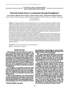
Fig. 4 Robot platform with three microphones for sound source localization; Infotainment Robot Platform Version 1[6]
Fig. 1 Sound source localization in free-field
GCC method [8].
delay and c is the speed of sound in air (343m/s). When the multi-microphone, 3 or more, are used to localize the source in an arbitrary position unlike using just two microphones, source directions estimated by each microphone pair may be different due to imprecision in the knowledge of system parameters and to unrealistic modeling assumptions (point source and perfectly free -field condition, etc.). The conventional ones estimate the source direction by using the information on only TDOA of cross correlation of each microphone pair. So the actual source direction is determined by the estimated source directions from each microphone pair and the specific error criterion [1]. However, the summed GCC method uses the whole information on the cross correlation function which is time domain function. The cross correlation functions of each microphone in time domain are transformed to the new function in spatial domain by using the specific mapping function as shown in Fig. 2 (b) and (c). Since the new functions are represented by the same spatial domain, the mapped functions are summed into the single function as shown in Fig. 3. And then a sound source is determined by finding the maximum of the summed single function. This approach is the summed
(a)
3. LOCALIZATION IN 3D SPACE We are going to explain how the summed GCC method can be used to localize the source in 3D space using 3 microphones in this chapter. As mentioned before, microphones should be placed on the robot platform as shown in Fig. 4. However, they shouldn’t be placed in the central plane of robot platform because it is necessary to discriminate the up-down confusion. If microphones are in the central plane, up and down effect of robot platform is same, and it is impossible to localize the source in 3D space uniquely. The robot platform is approximated to a sphere to obtain the mapping functions as shown in Fig. 5. If the measured HRTF is available, the mapping function can be obtained from the measured HRTF. Mapping functions are calculated by the analytic solution of the spherical head related transfer function (SHRTF). Some of mapping functions are represented as shown in Fig. 6. These mapping functions at the symmetric elevation are different unlike those of the free-field condition. These differences make the source localization in 3D space
(b)
(c)
Fig. 2 An example for the relationship between time lag of cross correlation and source direction; (a) microphone position and sound source is located in 0 degree, (b) cross correlations of each microphone pair, (c) the mapped function over the source direction of each microphone pair
Fig. 3 Summation of cross correlation mapped to source direction
242
mapping functions on 3D space as shown in Fig. 7 (a)~(c). Resolution of mapping functions over the elevation is 10 degree. After being mapped to the source direction, there appear circular shaped lines with the same magnitude because of cone of confusion [9]. Cone of confusion is perfectly circle in the free field condition. However, they are not perfect circle in this case due to the robot platform effect. Therefore, it is possible to localize the source in 3D space by finding the direction with a maximum of summed GCC function as shown in Fig. 7 (d).
Fig. 5 The approximated sphere model of the robot platform; radius of sphere (R) is 0.15m and offset (d) from central plane is 0.03m
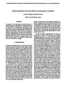
4. SIMULATION TO DEMONSTRATE THE FEASIBILITY We have performed a simulation to demonstrate the feasibility of the localization in 3D space with three microphones only using the summed GCC method. A spherical shape platform and three microphones as shown in Fig. 5 are used for simulation. Radius of sphere is 0.15m and offset from the central plane is 0.03m. Also three microphones are located with 120° interval on the plane paralleled with the central one. Source signal for simulation is the human speech filtered by the spherical head related impulse response (HRIR), which is the inverse Fourier transform of spherical HRTF [10]. Since the spherical HRIR includes the characteristics of diffracted and reflected wave caused by a sphere, the filtered signals can simulate the real measured signals. Signals for a specific direction are produced and then the direction of sound source is estimated with those signals. It is carried out as every 10 degree on 0°~180° azimuth and -70°~70° elevation. Speech signal to be applied in this simulation is “[an jΛŋ]” in Korean. Results for simulation are illustrated in Fig. 8. Results on azimuth angle estimation are excluded
Fig. 6 Mapping functions at the symmetric position on the platform as shown in Fig. 5
possible. Both azimuth and elevation angle of the sound source are estimated simultaneously by the summed GCC method with the whole mapping functions on 3D space. Cross-correlation functions are mapped to source direction on azimuth and elevation angles. When a source (speech signal) is located at 120° azimuth and -40° elevation, cross-correlation functions of each microphone pair are mapped to source direction by
(a)
(b)
(c)
(d) Fig. 7 The results that cross correlation functions of each microphone pair are applied by the summed GCC method with mapping functions on 3D space; (a) MIC.1 & 2 (b) MIC.2 & 3 (c) MIC.3 & 4 (d) Total summation result of all microphone pairs
243
because the performance of azimuth angle estimation has been already proved by the previous work [8]. These results show the good localization performance at the specific elevation angles which are -30°, -40°, -50°, 50° and 60°, because the mapping functions of those elevation angles are distorted by the platform enough to discriminate the up-down confusion compared with free field condition. However, there appears the up-down confusion at other elevation angles because difference between mapping functions of symmetric elevation angle is insignificant. So this approach should be applied when the source is located in the restricted region only, which is about -50° ~ 20° elevations. We can change the restricted region as we wish by tilting the plane with microphones of the platform. Finally, these simulation results demonstrate the feasibility of sound source localization in 3D space with three microphones only in restricted region.
important to search a proper microphone placement to be able to increase the platform effect as a future effort.
6. ACKNOWLEDGEMENT This work was supported by the Korea Science and Engineering Foundation (KOSEF) through the National Research Lab. Program funded by the Ministry of Science and Technology (R0A-2005-000-10112-0), the Brain Korea 21 Project and the IT R&D program of MKE/IITA [2008-F-044-01, Development of new IT convergence technology for smart building to improve the environment of electromagnetic waves, sound and building].
REFERENCES [1]
5. CONCLUSION [2]
We have shown a case where the sound source localization in some restricted region of the 3D space using the summed GCC method with three microphones only. It is possible to localize the sound source using the mapping functions that include the platform effect. However, in some elevation where the platform effect is insignificant, there appears the up-down confusion just as that in the free field condition. Therefore, it is
[3]
M. S. Brandstein and H. Silverman, “A practical methodology for speech source localization with microphone arrays,” Computer Speech and Language, 11(2):91-126, April 1997 A. O’Donovan and R. Duraiswami, “Microphone Arrays as Generalized Cameras for Integrated Audio Visual Processing,” Computer Vision and Pattern Recognition, CVPR'07. IEEE, 2007. Y. Sasaki, S. Kagami and H. Mizoguchi, “Multiple sound source mapping for a mobile robot by self-motion triangulation,” Proceeding of the 2006 IEEE/RSJ International Conference on Intelligent
Fig. 8 Simulation results on elevation estimation.
244
Robots and Systems, October 9-15. B. Kwon, G. Kim and Y. Park, “Considering microphone positions in sound source localization methods: in robot platform,” Proceeding of the KSNVE Annual Spring Conference, 2007 [5] H. Li, T. Yosiara, Q, Zhao, T. Watanabe, and J. Huang, “A Spatial Sound Localization System for Mobile Robots,” IEEE Instrumentation and Measurement Technology Conference, Warsaw, Poland, May 1-3, 2007 [6] S. Hwang, “Sound source localization using HRTF database,” Master’s Thesis KAIST, 2006 [7] S. Hwang, Y. Park, and Y. Park, “Sound Direction Estimation using Artificial Ear,” International Conference on Control, Automation and Systems, Oct. 17-20 in COEX, Seoul, Korea, 2007 [8] B. Kwon, Y. Park and Y. Park, “Sound Source Localization in the Non Free-Field Condition; Spherical Platform,” 15th International Congress on Sound and Vibration 6-10 July 2008 [9] C. I. Cheng and G. H. Wakefield, “Introduction to Head-Related Transfer Functions (HRTFs): Representations of HRTFs in Time, Frequency, and Space,” Journal of Audio Engineering of Society, Vol. 49, No. 4, 231-249, 2001 [10] Duda, R. O. and Martens, L. W., “Range dependence of the response of a spherical head model,” Journal of acoustical society of America, Vol. 104, No.5, 1998. [4]
245