Abstract- This paper present Static Random Access Memory. (SRAM) cell with minimum number of transistor. A conventional. SRAM cell requires 6 transistors ...
Proceedings of 2014 RAECS UIET Panjab University Chandigarh, 06 - 08 March, 2014
SRAM Cell Design with minimum number of Transistor Abhishek Kumar ECE Dept Lovely Professional University Abstract- This paper present Static Random Access Memory (SRAM) cell with minimum number of transistor. A conventional SRAM cell requires 6 transistors having two nodes contains normal and complimented data. The scaling of CMOS technology has significant impacts on working of SRAM cell. In 4T cell reading and writing has been performed by each node separately [1]. In this paper SRAM cell (2T) designed and comparison between them made in terms of power consumed, access time and PDP. A 2T cell contains single node, read and write performed through same node. It is found that in 2T cell area reduces by more than 66% maintaining same access time but at the cost of power consumption. Keywords—SRAM, Cadence Virtuoso, 6T SRAM Cell
I.
INTRODUCTION
High speed static random access memory is the primary requirement of multimedia applications in hand held devices. Memory is the major component of any chip. According to ITRS roadmap 90% of chip area will consume by memory. Around 30% of the semiconductor business (world-wide) is due to semiconductor memory chips. SRAMs are widely used for as both on-chip and off-chip memories [3]. A conventional SRAM cell contains 6 transistors. SRAM cell (6T) contains two inverter connected back to back, requires more number of transistor take more space on chip but it faces difficulty meeting the growing demand for a larger memory capacity. In response to this requirement, our objective is to develop an SRAM cell with less number of transistors to reduce the cell area size. SRAM cell with 4 transistors has been already proposed in [1]. Where reading has been performed form one side and writing on other side of cell, but due to more number of transistors memory chip area widely enhanced. 4T SRAM cmos cell opens a wide area of research for smaller size sram cell. Cell size is 33% smaller than conventional six transistor cell. 4T sram cell used for high density and low power application as well as high speed memory. In this paper, a new SRAM cell (2T) with 2 transistors has been developed. It contains a driver and a load transistor. Cell size reduce by 66% than conventional .A 2T SRAM cell have only one node reading and writing can be performed from same node. Other than SRAM cell memory consist of precharge circuit for maintaining stored data, sense amplifier to retrieve data from cell and control circuitry to accomplish writing and reading to and fro through cell. Proper cell sizing must be done to maintain data written data and it should not change after reading discussed in [5]. In this paper working of 6T, 4T and 2T cell has been explored. All schematic has been designed in
978-1-4799-2291-8/14/$31.00 ©2014 IEEE
cadence virtuoso and simulated in cadence spectre 180nm CMOS technology. II.
DIFFERENT CELL ARCHITECTURE
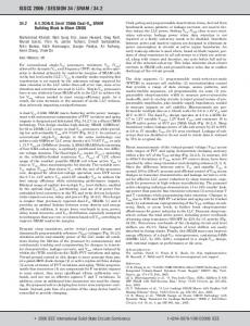
A. Conventional 6T SRAM A conventional 6T transistor contains, 2 cross coupled inverter (output of transistor fed to others input) and two access transistor as shown in figure1. Output node of each inverter stores charge during write cycle and access transistor provides access to SRAM cell during read cycle. Access to SRAM cell is enabled by word line (WL) which controls the gate input of access transistor. Access transistor control cell connected to BL or BLB (Bit line) they used to transfer data for both read and write operations.[4,5]
Figure 1 6T SRAM [5]
Figure2 shows simulated waveform for read/write operation of 6T SRAM cell in 0.18µm CMOS technology. Writing a bit into the SRAM cell is done by forcing one of the bit lines high while keeping the other low. To write “1” into the SRAM cell the word line (WL) is asserted bit line BL is made high and bit line BLB is made low. To write “0” into the SRAM bit line BL is made low and BLB is made high. Before reading from SRAM cell both bit lines are precharged close to supply voltage. A particular cell selected by WL to be read, charge stored at node discharges through BL and BLB. Bit line of particular cell acts is input to sense amplifier. The sense amplifiers amplify difference of data which is present on the bit lines. BL and BLB makes a differential amplifier, voltage
difference between them amplified and decides whether node voltage was high lo low. If voltage at BL < BLB output amplify to logic 0 else if voltage at BL > BLB output amplify to logic 1. Figure2 shows the simulation result of reading and writing through 6T cell. A more the sensitive sense amplifier performs reading with higher speed.
must be adjusted discussed in [1]. Figure2 shows the simulation result of reading and writing through 4T cell. During write operation BL and BLB line is prechaged to supply voltage. Charge on ST and STB node discharge through BL and BLB line. Difference in voltage between BL and BLB senses by sense amplifier and data has been read from output of sense amplifier Y.
Figure 2 Reading -Writing in 6T SRAM cell
Figure 4 Reading-Writing in 4T SRAM Cell
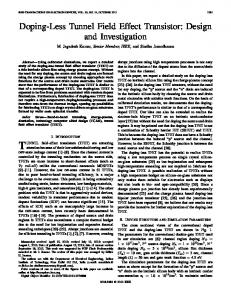
B. 4T SRAM Cell Fig. 3 shows a 4T SRAM cell in 0.18µm CMOS technology. A 4T SRAM contains 4 transistors, a pair of pmos and nmos make twisted inverter and two nmos as access transistor In inverter nmos works as driver transistor and pmos works as load transistor. Unlike 6T cell it requires 4 mos a pair of mnos and pmos forms cross coupled inverter and 2 nmos for access transistor used to access cell to transfer data during read and write cycle. 4T SRAM employ reading and writing on each node separately [1, 2].
To read ‘0’, voltage on ST node is low the voltage of BL pulled down to low voltage by access transistor. When SE goes high enable sense amplifier and read data ‘0’ at Y. To read ‘1’ when voltage on ST node is high the voltage of BL and ST node approximately same SE enable sense amplifier and read data ‘1’at output of sense amplifier[1]. C. 2T SRAM Cell Figure 5 shows a new proposed 2T SRAM cell at supply voltage of 1V in 180nm CMOS technology. A new SRAM cell with 2 transistors has been proposed. In this cell there is a driver transistor nmos and a load transistor of pmos. Data can be stored on the interconnection of both transistors Q. Driver transistor works as access transistor as well. Gate input of NMOS connected to WL line which proved access to 2T cell during read and writes cycle. In this circuit a single bit line BL used to unlike 2 bitline in 6T and 4T cell. Since 2T cell requires single bit line it’s precharge and sense amplifier is also single ended. Charge stored on BL drives sense amplifier and determine logic value at output Y. Cell area has been reduced by 66% without affecting the sram working.
Figure 3 4T SRAM Cell [1]
There is feedback between two nodes, WL line used for transferring new data into the cell. Reading and writing operation of 4T SRAM cell is similar to 6T SRAM cell except data has been written on STB node instead of ST node. During write cycle complement of data has been placed on STB node and opposite data has been placed on ST node, WL line turn ON access transistor and data is transferred to ST and STB node. To write '0' into cell; load and driver transistor are ON therefore ST node discharges to ground by drive transistor and STB node charged to VDD by load transistor. To write '1' into cell load and driver transistor is OFF. For data retention without refresh cycle threshold voltage of each mos
Figure 5 2T SRAM Cell
To write data has to be placed on BL and turn on driver transistor. If data is “1”, WL turns on access transistor which forces Q to 1 maximum value (Vdd-Vth). If data is “0” node Q finds a direct path to ground. Charge stored on node Q discharges through driver transistor. Load transistor discharges to ground through node Q maintain low voltage at node Q. To
maintain charge on node Q driver transistor 3times wider than load. In this case there is a direct path from Vdd to ground which going to increase dynamic power. Read cycle is started by enabling SE signal, voltage on BL sensed by sense amplifier as shown in figure6.
[4]
[5]
Figure 6 Reading-Writing in 2T SRAM Cell Power
PDP
Delay
SRAM Cell
Av. Power in one Cycle
Write Delay
Read Delay
6T
922.7uw
282.2p
Power* Write Delay(E-15)
Power*Read Delay (E-15)
9.73n
260
8977 40 893931
4T
64.74uw
152.4p
618p
9.84
2T
59.24mw
15.19n
15.09n
899855
Table I Comparison table of different cell
For 2T cell, read cycle finds a direct path from supply to ground it greatly increases the dynamic power. Power consumption in 2T cell is much greater than other cell as shown in table 1. If data on node Q is ‘1’ it turns off pmos node discharges through driver transistor but when data on naode Q is ‘0’ it turn on pmos and pmos stays on which leads to power consumption. One extra read1 cycle required to reduce power consumption. III. CONCLUSION Fewer transistors play an important role in designing high density SRAM where large. 6T and 4T SRAM cell contains two nodes. Data and their compliment have been holding on each node. While in 2T contains single node reading and writing can be performed on same node. Area of cell reduced by more than 65%. Read and write delay into 2T cell is comparable to other configuration. Power consumption in 2T cell is higher but it can be reduce if after read0 there is an extra cycle either read1 or write. REFERENCES [1]
[2]
[3]
Arash Azizi Mazreah, Mohammad T. Manzuri Shalmani, Hamid Barati, and Ali Barati, “A Novel Four-Transistor SRAM Cell with Low Dynamic Power Consumption,” World Academy of Science, Engineering and Technology 39 2008. Pp 77-81 Deepa Yagain, Ankit Parakh, Akriti Kedia,Gunjan kumar Gupta, “Design and implementation of High speed, Low area Multiported loadless 4T Memory cell” 2011 Fourth International Conference on Emerging Trends in Engineering & Technology, I EEE Computer society, 2011, pp 268-273 Ravi Kumar. K. I, Vijayalaxmi. C. Kalal, Rajani. H. P, Dr. S. Y.Kulkarni “Design and Verification of Low Power 64bit SRAM System using 8T SRAM:Back-End Approach” International Journal
of Engineering and Innovative Technology (IJEIT) Volume 1, Issue 6, June 2012, pp147-153 Ajay Kumar Dadoria, Arjun Singh Yadav, C.M Roy “Comparative Analysis Of Variable N-T Sram Cells” International Journal of Advanced Research in Computer Science and Software Engineering,Volume 3, Issue 4, April 2013 CMOS digital integrated circuit, 2nd edition SUNG-MO (STEVE) KANG &YUSUF LEBLEBIGI, WCB McGraw-Hil