2010 Pacific Rim International Symposium on Dependable Computing
System-Level Vulnerability Estimation for Data Caches Alireza Haghdoost1 1 2
Hossein Asadi1
Amirali Baniasadi2
Department of Computer Engineering, Sharif University of Technology, Tehran, Iran Department of Electrical and Computer Engineering, University of Victoria, Canada
[email protected] [email protected] [email protected]
with cache size for the next several years. Accordingly, designers would need to incorporate aggressive protection techniques in future cache designs. An important aspect of designing cost-effective protection techniques is developing accurate soft error vulnerability models for individual components. This will help understanding the extend of vulnerability for different components before developing protection techniques. Having an accurate model for cache memories would facilitate making informed decisions about the level of protection needed across different cache organizations and target workloads. The right protection level for cache memories reduces data loss probability and therefore would increase system reliability. The most commonly used technique to compute cache vulnerability to SEUs is exploiting Fault Injection (FI) schemes [5], [6], [7], [8]. Using FI schemes, a limited number of sites are selected for fault injection in applications running for a limited number of clock cycles for each iteration of fault injection. FI techniques are both time-consuming, due to the large number of runs, and prone to inaccuracy, due to the limited number of addresses targeted. An alternate approach to compute cache vulnerability is to use analytical models [9], [10], [11], [12]. Such models often provide fast estimation; however, they suffer from inaccuracies. This is due to the fact that these analytical models mainly rely on measuring the time period in which an error occurring in a data block could propagate in the system, also referred to as the Critical Time (CT), to estimate vulnerability. While critical time is an important factor, it is not the only one. In this paper, we introduce System level Vulnerability Factor (SVF) as a new vulnerability estimation technique for data cache. which while considering previously ignored parameters maintains low estimation time. In our proposed modeling technique, we take into account two important factors ignored in previous studies. The first important parameter is read frequency. We define read frequency as the number of times a data block is accessed during the critical time. Intuitively, we expect a block read several times during its critical time, more influencing than one read only once. While both blocks are equally vulnerable to SEUs, the former is more likely to propagate an error to the system outputs, leading to system failure. This is due to the fact that each read access provides an opportunity for an error to find its way to the system outputs. Therefore, the higher the number of reads the higher the risk of having a cache error impacting the overall system reliability. The second important factor influencing vulnerability is error masking. Quite often an error occurring in the cache could
Abstract—Over the past few years, radiation-induced transient errors, also referred to as soft errors, have been a severe threat to the data integrity of high-end and mainstream processors. Recent studies show that cache memories are among the most vulnerable components to soft errors within high-performance processors. Accurate modeling of the Vulnerability Factor (VF) is an essential step towards developing cost-effective protection techniques for cache memory. Although Fault Injection (FI) techniques can provide relatively accurate VF estimations they are often very time consuming. To overcome the limitation, recent analytical models were proposed to compute the cache VF in a timely fashion. In this paper, we extend previous work and propose an alternative analytical model to compute System-level Vulnerability Factor (SVF) for both write-through and write-back data caches. In our proposed analytical model, we take into account both read frequency and error masking to compute systemlevel vulnerability of data cache. Previously suggested modeling techniques overlook the issues of read frequency and error masking, mainly focusing on time periods in which an error could propagate in the system. In this work we show that overlooking these two parameters can significantly impact the system-level VFs for data caches. We report our estimations for SPEC’2K benchmarks and compare to previously suggested models. Our experimental results show that the proposed modeling technique changes previous VF estimations by up to 40%. Index Terms—System level vulnerability estimation, Architectural vulnerability factor, Cache memory
I. I NTRODUCTION As CMOS technology continues to scale down, the issue of estimating and mitigating the impact of radiation-induced transient errors becomes more challenging. Radiation-induced transient errors (also known as soft errors) caused by neutrons and alpha particles from packaging are known to be a considerable reliability threat to the data integrity of high-end and mainstream processors. cache data integrity has been a main concern for processor designers as errors in cache memory can quickly propagate to higher memory levels, and lead to data integrity issues [1], [2]. Recent research has shown that soft errors could have significant impact on cache data integrity [3]. A previous study uses field results over several thousands of systems, and shows that 92% of system reboots are initiated by Single Event Upsets (or SEUs) occurring at first-level (L1) and second-level (L2) cache memories [3]. Another study estimates that unprotected SRAMs contribute to at least 40% of the overall Soft Error Rate (SER) of commercial digital circuits [4]. With continuous technology scaling down, per bit SER in SRAMs is estimated to maintain relatively unchanged [4]. Consequently, cache soft error rates are expected to increase
978-0-7695-4289-8/10 $26.00 © 2010 IEEE DOI 10.1109/PRDC.2010.9
157
be masked by other components before reaching the system output. We take this probability into account and reevaluate cache vulnerability accordingly. We report our estimations for SPEC’2K benchmarks and compare to previously suggested models. In particular, our results show that the proposed modeling technique changes the previously suggested estimations by more than 40%. The rest of the paper is organized as follows. In Section II we review background on soft errors and vulnerability estimation. In Section III we present previous vulnerability modeling techniques and their limitations. In Section IV we explain the inaccuracies existing in previous analytical techniques and describe our motivating observations. In Section V we present our vulnerability modeling technique. In Section VI we review the algorithm used to compute the system-level vulnerability for data cache. In Section VII we review the experimental setup. In Section VIII we discuss our methodology and report results. Finally, in Section IX we offer concluding remarks. II.
memory is more complicated because an erroneous value in such components can be masked by the CPU [15]. T V F is the fraction of time for which the circuit is vulnerable to transient faults. As an example, a simple latch is vulnerable against radiation-induced faults during 50% of its clock cycle time [15]. SRAM cells (used in cache memory) are always susceptible to these faults. Therefore, the associated TVF for SRAMs is 100%. Finally, RawF ITrate is the circuit-level soft error rate of a device from radiation-induced faults. RawF ITrate of a storage element relies on the device characteristics and the flux that comes across the device [15]. III. P REVIOUS V ULNERABILITY FACTOR M ODELING T ECHNIQUES Statistical Fault Injection (SFI) is commonly used in most previously proposed cache reliability estimation methods [5], [6], [7], [16], [17], [8]. When using an SFI technique, a limited number of memory addresses are targeted. Several workloads are then run to measure the number of detected failures. Consequently, SFI studies are both time-consuming (due to the large number of runs), and prone to inaccuracy (due to the limited number of addresses targeted). Li et al. introduced SoftArch as a model (and a tool) to enable soft error analysis at the architecture level [18]. SoftArch uses a probabilistic error generation and propagation process model in the processor. This tool, however, does not consider device or circuit level details and does not support application level masking. Somani et al. presented a cache error propagation modeling technique [19]. The proposed model uses software fault injection to determine the cache vulnerability to soft errors. Kim et al. used the same model to measure data cache access reliability [1]. They also studied tag array soft error susceptibility [1]. Mukherjee et al. [10], [20] introduced the ACE analysis method to quantify the architectural masking of soft errors in different processor structures using the processor performance model. The AVF of a structure is the likelihood of a failure occurring as a result of a raw error event in the structure. To measure the AVF of a structure, the bits that affect the final program outcome are identified on a cycle-by-cycle basis. These bits are referred to as Architecturally Correct Execution (or simply ACE) bits. All other bits are termed un-ACE. Examples of un-ACE bits are the operand bits of an NOP instruction or opcode bits in a killed instruction. All bits are assumed as ACE bits unless proven un-ACE. Biswas et al. extended the ACE analysis method to cover caches and other address-based structures [11]. The proposed model extends AVF measurement to data and tag arrays but does not cover status bits. The model determines the vulnerability factor of a cache based on the ACE lifetime of cache words. Asadi et al. introduced a critical time model to estimate the reliability of an unprotected or partially protected cache memory [9]. The proposed model computes cache vulnerability
BACKGROUND
An energetic particle striking a CMOS transistor induces a localized ionization capable to change the state of a memory cell, logic gate, latch, or flip-flop causing a soft error [13]. In the past two decades, researchers have discovered three major sources that cause soft errors in semiconductor devices at terrestrial altitudes. These sources are a) alpha particles, b) high-energy neutrons, and c) low-energy neutrons interacted with the isotope boron-10 (10 B) [14]. Soft Error Rate (SER) is defined as the system failure rate due to soft errors. Failures-in-Time (FIT) is another commonly used error rate metric. FIT of a component is inversely proportional to Mean-Time-To-Failure (MTTF) of the component. This is shown in Equation 1. One FIT is equal to one failure in a billion hours. F ITrate =
109 M T T F × 24hours × 365days
(1)
The overall FIT of a chip is calculated by adding the effective FIT rates of all the individual components as follows [9]: F ITchip =
X
F ITComponent(i)
(2)
i
The FIT of each component in a chip is the product of its raw FIT rate, associated Architectural Vulnerability Factor (AVF), and Timing Vulnerability Factor (TVF) as follows: F IT = AV F × T V F × RawF ITrate
(3)
AV F expresses the probability that a transient fault in a storage cell (like SRAM) results in a user visible error [10]. For example, a bit-flip in a branch predictor may cause a misprediction, however, it will never result in a user-visible error. As a result, the branch predictor’s AVF = 0%. In contrast, a bit-flip in a program counter register will almost crash the instruction execution sequence and produce control flow error. Therefore, a program counter’s AVF is about 100%. Computing the AVF of other components such as cache
158
using the residency time of critical words (CW) in the cache. A CW is defined as a word in the cache that is guaranteed to propagate to other locations in the memory system or to the CPU. They used the proposed model to develop a simulation model and measure the reliability of L1 caches. S. Wang et al. introduced Temporal Vulnerability Factor as a soft error characterization model [12] to capture the cache vulnerability factor upper bound. The proposed model extends the work presented in [9] by calculating the critical times at various granularity levels, e.g. a cache line, a word, or a byte [12]. Li et al. studied the limitations of AVF modeling [21] and showed that AVF estimations can result in large discrepancies where the raw error rates of individual components are very large or when one considers tens of thousands of computers. As an example, they showed that in space applications the calculated vulnerability factor using AVF is twice bigger than the actual vulnerability factor. N.J. Wang et al. reported that statistical fault injection (SFI) at register transfer level (RTL) can generate more accurate AVFs compared to ACE analysis [22]. In response, Biswas et al. [23] claimed that by adding more detail to the performance model, they can reduce the discrepancy produced by AVF using ACE analysis with SFI AVF. As an example, by adding more detail to the instruction queue model, they reduced the ACE AVF over-estimation up to 40% from the 260% discrepancy reported in [22]. In this work we show that ACE analysis could further be improved by taking into account issues such as read frequency and error masking. We present more details in section IV. In our previous work, we proposed Input-to-Output Masking (IOM) factor to estimate system-level vulnerability of datapath components in a high-performance processor [24]. Using the IOM factor, we also presented a modeling technique to estimate the Component-level Vulnerability Factor (CVF) and the System-level Vulnerability Factor (SVF) of the datapath components. In this paper we extend our previous work for data caches and provide detailed systematic approach to estimate SVF of cache memories. In particular, we present a methodology to compute SVF for both write-back and writethrough data caches.
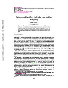
A. Read Frequency To provide better understanding regarding the impact of read frequency we offer an example in Fig. 1. Let’s consider the two case studies (case A and case B) presented in Fig. 1. In case A, a block is brought to the L1 cache at t1 and read by the CPU at t5 . Later the block is evicted from the cache at t6 . In case B, a block is brought to the cache at t1 and read by the CPU at t2 , t3 , and t5 . Eventually, the block is evicted from the cache at t6 . According to previous AVF modeling techniques, the vulnerability of these two cases is computed as follows: V ulCaseA = t5 − t1 V ulCaseB = (t2 − t1 ) + (t3 − t2 ) + (t5 − t3 ) = t5 − t1
(4)
Note that according to previously suggested modeling techniques, the vulnerability of these two cases are equal. This is not an accurate estimation as the impact of these two read patterns on the overall system failure rate could be very different. While in case A, the error has a one-time opportunity to propagate to the system outputs, in case B the error can propagate to the system outputs at three different occasions.
Fig. 1. An example with two different access patterns to demonstrate previous method limitations.
B. Error Masking To provide better understanding regarding the masking impact we present an example in Fig. 2. Assume that a byte within data cache is struck by an SEU changing one of its eight bits. The target byte is then read by the CPU and is sent to the ALU unit. Previous VF estimation methods mark the entire byte as ACE as all bits could produce an error. Let’s also assume that the byte is used as an operand in a Logical OR arithmetic operation. Although the incorrect value of the byte is transferred from the cache to the inputs of the ALU unit, it does not necessarily propagate from the ALU inputs to the outputs of the ALU unit. To elaborate this in more detail, assume that the target byte’s initial value is 0x1A (denoted in hexadecimal format). Let’s also assume that an SEU event inverts the most significant bit of this byte, changing the byte from 0x1A to 0x9A. If this byte is used as an operand of a logical OR operation with a second operand equal to 0x83, the incorrect value of the byte would not propagate to the outputs of the ALU unit. This is because the logical OR will mask the error bit when producing the final outcome, i.e., (0x1A OR 0x83) = (0x9A OR 0x83) = 0x9B. Previous work has introduced the Derating Factor (DF) to quantify the masking behavior [26]. DF is defined as the
IV. L IMITATIONS OF P REVIOUS A NALYTICAL M ODELS : R EAD F REQUENCY AND E RROR M ASKING Previous vulnerability analytical models suffer from two drawbacks. First, such models compute the vulnerability window independent of the cache access pattern. As explained earlier in Section I, each read access can expose the system to an erroneous bit. As a result, the more frequent read operations occur the higher the likelihood of the system failure. Second, such studies [9], [25], [12], assume that any error propagating from cache to the CPU leads to a system failure. As we show in this work many errors could potentially be masked by different processor components. Below we explain both factors in more details.
159
probability of propagating an incorrect value along logical paths. In particular, DF [26], [27] is expressed as the probability of propagating an erroneous value from an internal site to the circuit outputs. In this paper, we extend this concept to compute the error propagation probability from the cache memory to the outputs of the CPU.
The next two terms model errors being masked by the CPU after the earlier read but propagated by a subsequent read access. For example, (t2 − t1 ) × IOMcpu × (1 − IOMcpu ) represents the likelihood of an error masked by the CPU after being read by R1, impacting the CPU output later by being read (and not being masked) by R2. The last term, 2 (t2 − t1 ) × IOMcpu × (1 − IOMcpu ), represents an error occurring during t2 − t1 , masked by the CPU after both R1 and R2, but propagated by to the system output after R3. Note that if a byte within a dirty block is written back to the memory system, the masking factor of the CPU will not affect the vulnerability of the byte. Under this scenario, the erroneous block would most likely impact the system output eventually. To provide better understanding, in Table I we report SV for case A and B and for different IOM values. In this table, we assume t0 = 0, t1 = 1, t2 = 2, t3 = 3, t4 = 4, t5 = 5, and t6 = 6. We also report ACE time (or critical time) [9], [10], [11], [12] to make comparison possible. Note that SV and CT estimations are different for all IOM values but IOM = 0.
V. P ROPOSED M ODEL
TABLE I C OMPARISON SV AND CT FOR THE EXAMPLE GIVEN IN F IG . 1.
Fig. 2.
Example of error masking in a CPU.
As stated in section IV, in order to accurately compute the vulnerability of data cache, we need to consider the impact of error masking and read frequency. In this work we use CPU Input-to-Output Masking (IOM ) to model CPUs masking behavior [24]. We define IOMcpu as the probability of an erroneous value read by the CPU not being propagated to the outputs of the CPU. As an example, if 60% of erroneous values read by the CPU are masked by the CPU and not propagated to the outputs of the CPU, then IOMcpu = 0.6. As explained earlier, a previous study has defined a Critical Word (CW) or Critical Byte (CB) as a word or a byte guaranteed to propagate from the cache to other locations in the memory system or to the CPU [9]. The residence time of the CB (or CW) in the cache is referred to as the Critical Time (CT). Here, we extend this concept to better estimate the impact of cache vulnerability factor on the overall system reliability. We define System-level Vulnerability (SV) of a byte within a cache memory as the sum of the time periods where an incorrect value in those time periods leads to system failure. As an example, let’s consider case B presented Fig. 1. Here, the SV of the byte can be computed according to Equation 5.
IOM 0.8 0.6 0.4 0.2 0
Case B SV CT 1.248 4 2.224 4 2.976 4 3.552 4 4 4
SV analysis formulation could vary based on different cache access patterns. An erroneous data in a cache block results in system failure in one of the following scenarios: • An erroneous block is directly written back to main memory. • An erroneous block is read by CPU, then an erroneous result is generated by the CPU, and written back to the main memory. The former scenario has been addressed in previous work [12], [9], [25]. Therefore in this work we focus on the second scenario. In our proposed VF modeling technique, we identify three important scenarios not studied by previous work. Under the first scenario we assume that the accessed block remains clean during the critical time and is evicted on cache block replacement. Under the next two scenarios we assume that the accessed block becomes dirty sometime during critical time and is written back to L2 cache on cache block replacement. Here we describe these cases as follows: • Case 1: Clean Block Under this scenario, the block is clean, i.e., all bytes in the block are only accessed by read operations. This is shown as Case 1 in Fig. 3. We use Equation 6 through Equation 8 to calculate SV of the byte. In these equations, SV (F : R1 ) computes SV from the fill time to the first read operation (R1). SV (F : R2 ) computes SV from the
SVCaseB = (t2 − t1 ).(1 − IOMcpu ) +(t3 − t2 ).(1 − IOMcpu ) +(t5 − t3 ).(1 − IOMcpu ) +(t2 − t1 ).IOMcpu .(1 − IOMcpu ) +(t3 − t2 ).IOMcpu .(1 − IOMcpu ) 2 +(t2 − t1 ).IOMcpu .(1 − IOMcpu )
Case A SV CT 0.8 4 1.6 4 2.4 4 3.2 4 4 4
(5)
The first three terms, (t2 − t1 ) × (1 − IOMcpu ), (t3 − t2 ) × (1 − Iomcpu ), (t5 − t3 ) × (1 − IOMcpu ), represent the likelihood of an error occurring in t2 − t1 , t3 − t2 and t5 − t3 being propagated to the system outputs by the read accesses immediately following (here R1, R2, and R3, respectively).
160
•
Fig. 3.
Read/write patterns to compute vulnerability.
fill time to the second read operation (R2), and finally, SV (F : R3 ) computes SV from the fill time to the third read operation (R3). Note that in Equation 6 through Equation 11 we assume that tF ill = t0 = 0. SV (F : R1 ) = t1 .(1 − IOMcpu )
Case 3: Dirty Block with Write Operation on the Target Byte Under this scenario the block is dirty and the target byte is accessed by both read and write operations. This is shown as Case 3 in Fig. 3. Here, we have assumed there are n read and k write operations on the target byte. In this figure, tri is the time of ith read operation and twj is the time of j th write operation. In order to calculate SV of the target byte, we first compute the SV of the time period between twj−1 to twj according to Equation 9. We call this vulnerability SV (twj ). Then, we use Equation 11 to calculate SV. Since the block will be written back to higher memory levels at the evict time, we use the last term of these two equations (i.e., tevict − twk ) to account for the vulnerability of the target byte from the last write operation time to the evict time. SV = SV (tw1 ) + ... + SV (twk ) + (tevict − twk )
We use conventional lifetime analysis proposed in [12], [9] for computing vulnerability in other situations. The lifetime model distinguishes among nine lifetime phases for each byte according to the previous activity and the current status, and further categorizes them into two groups, vulnerable and non-vulnerable phases. Five lifetime phases, WRP, RR, WR, WPL and WRPL are vulnerable and we will consider their vulnerability time. The other lifetime phases, RPL, Invalid, RW, and WW are non-vulnerable. Note that since we propose fine grained (per byte) lifetime analysis on data items, RW and WW are unconditionally non-vulnerable. Once the SV of all bytes are calculated, we can compute the SV and SVF of the data cache as follows:
(6)
SV (F : R2 ) = t1 .(1 − IOMcpu ) + (t2 − t1 ).(1 − IOMcpu ) +t1 .IOMcpu .(1 − IOMcpu ) = (t2 + t1 .IOMcpu ).(1 − IOMcpu ) = t2 .(1 − IOMcpu ) + t1 .IOMcpu .(1 − IOMcpu ) = t2 .(1 − IOMcpu ) + SV (F : R1 ).IOMcpu (7) SV (F : R3 ) = t1 .(1 − IOMcpu ) + (t2 − t1 ).(1 − IOMcpu ) +(t3 − t2 ).(1 − IOMcpu ) +t1 .IOMcpu .(1 − IOMcpu ) +(t2 − t1 ).IOMcpu .(1 − IOMcpu ) 2 +t1 .IOMcpu .(1 − IOMcpu ) 2 = (t3 + t2 .IOMcpu + t1 .IOMcpu ).(1 − IOMcpu )
= t3 .(1 − IOMcpu ) + (t2 .(1 − IOMcpu ) SVCache =
+t1 .IOMcpu .(1 − IOMcpu )).IOMcpu = t3 .(1 − IOMcpu ) + SV (F : R2 ).IOMcpu
(8) SV FCache =
SVi
(12)
SVCache TT × M
(13)
In this equation, T T is program runtime. M is cache size in bytes, and N is the total number of bytes for which SV is computed. VI. A LGORITHM
SV (F : Rn ) = tn.(1 − IOMcpu ) + SV (F : Rn−1 ).IOMcpu (9)
We use Algorithm 1 to compute SV of all individual bytes. In lines 9 through 11 and lines 16 through 20, we compute SV of a dirty byte within a dirty block. SVbi ,lw are used to computed SV (twj ) according to equation 11. In line 29, we account for the vulnerability of the target byte from the last write operation time to the evict time according to equation 11. In lines 13 through 15, we compute SV of a clean byte within a clean block according to equation 9. In line 32, we compute SV of a clean byte within a dirty block according to equation 10. Finally, in lines 40 through 44, the overall SV and SVF are computed according to equation 12 and equation 13, respectively.
Case 2: Dirty Block with no Write Operation on the Target Byte Under this scenario the block is dirty but the byte is only accessed by read operations. That is other bytes within the block have been accessed by both read and write operations but the target byte is only accessed by read operations. This is shown as Case 2 in Fig. 3. Since the block is dirty it will be written back to higher memory levels. Therefore, all bytes within the block are vulnerable from the filling time to the evict time. We use Equation 10 to calculate SV of the target byte. SV (F : Rn ) = tevict
N X i=1
In general, for n successive read operations, we use Equation 9 to compute SV from the fill time to the last read operation. In this equation, SV (F : Rn−1 ) is the SV of the target byte from the fill time to (n − 1)th read operation.
•
(11)
(10)
161
1 2 3 4 5 6 7 8 9 10 11 12 13 14 15 16 17 18 19 20 21 22 23 24 25 26 27 28 29 30 31 32 33 34 35 36 37 38 39 40 41 42 43 44 45
TABLE II D EFAULT CONFIGURATION PARAMETERS USED IN OUR SIMULATIONS .
Algorithm: Compute SVF bi : Byte ith in a cache block Bj : Block j th in a set SVbi : System-level Vulnerability of Byte bi SVbi ,lw : SVbi from Last Write Operation to now T SC: Total Simulation Cycle N CB: Number of Bytes within Cache Memory begin if W RIT E HIT then SVbi ,lw =0 end if READ HIT then if Bj not dirty then SVbi = (now - FillTime) * (1 − IOMcpu ) +SVbi *IOMcpu end else if bi dirty then SVbi = SVbi − SVbi ,lw SVbi ,lw = (now - LastWriteTime)* (1 − IOMcpu ) + SVbi ,lw × IOMcpu SVbi = SVbi + SVbi ,lw end else No action needed end end if Evict OR F lush Bj (W riteBack) then if Bj is dirty then for each bi in Bj do if bi is dirty then SVbi = SVbi + now - LastWriteTime[bi ] end else SVbi = (now - FillTime[bi ]) end end end end if Evict OR F lush (W riteT hru) then No action needed end if End of simulation then Start cool-down process SVcache = add all SVbi ’s SV Fcache = SVcache / (T SC × N CB) end end
Configuration Parameter Value Processor Functional Units 4 integer ALUs 4 integer multiplier/divider 1 FP ALUs 1 FP multiplier/divider LSQ Size / RUU Size 32 Instructions / 32 Instructions Fetch / Slot / Map Width 4 / 4 / 4 instructions/cycle Issue / Commit Width 4 / 11 instructions/cycle Integer/FP issue queue size 20 / 15 instructions Reorder buffer size 80 instructions Register file 40 FP / 40 Integer entry Return address stack 32-entry Victim buffer 8 entries, 1-cycle hit latency MSHR entries 8/cache Prefetch MSHR entries 2/cache Cycle Time 1 ns TLB and Cache Memory Hierarchy TLB 128-entry ITLB/128-entry DTLB, fully-associative L1 Instruction Cache 64KB, 2-way, 64 byte lines (IL1) 1 cycle latency L1 Data Cache 64KB, 4-way, 64 byte lines (DL1) 3 cycle latency L2 2MB unified, direct-mapped 64 byte lines, 7 cycle latency Memory 100 cycle latency Branch Logic Predictor Hybrid, 4K global two-level 1KB local, 4K choice BTB 512 entry, 4-way Mis-prediction Penalty 7 cycles
Our results show that even with 100 iterations, the computed IOM is as accurate as 400 times iterations. Our evaluation uses the SPEC’2K benchmark suite [30] compiled for the Alpha ISA [31]. We run our benchmarks for 100M instructions and 100M cool-down after skipping the first 100M instructions. The default system parameters (cache size, associativity, etc.) are detailed in Table II, and were chosen to be representative of modern state-of-the-art processors. We report IOM for the applications studied here and for the configuration presented earlier. We report SVF and AVF for both write-back and write-through caches. Since most modern processors utilize ECC protection on their L2 caches and main memory, in this study we focus on L1 caches.
Algorithm 1: SVF computation for both write-back and write-through cache memories.
VII. E XPERIMENTAL S ETUP We used the sim-alpha processor simulator [28]. To evaluate the reliability of DL1 caches, we have extended the sim-alpha source code to integrate our reliability estimation method and the write-through cache. We have also incorporated AVF estimation algorithms from sim-soda [29]. To estimate how often the CPU masks an error occurring in the cache (here referred to as IOM) we modified sim-alpha. In our estimation method we flipped one bit in a randomly selected load instruction operand and investigated whether the modified data reaches the CPU output. We follow this procedure 400 times per applications and report the percentage of the time the error does not propagate to the CPU output as an IOM estimation. Our experimental results show that the computed SVF is not sensitive to the total number of iterations used to extract IOMs.
VIII. R ESULTS In this section we report results. In subsection VIII-A we present experimental setup to measure IOMcpu and then report the calculated IOM. In subsection VIII-B we report SVF and AVF for the write-back cache. In subsection VIII-C we report SVF and AVF for the write-through cache. Finally in subsection VIII-D we report vulnerability estimation change compared to AVF for our suggested model.
162
Fig. 5.
Fig. 4.
IOM sensitivity to the total number of application runs.
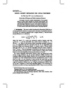
Estimating IOMCP U
A. IOM In order to measure the IOMCP U , we inject a limited number of faults using the model depicted in Fig. 4. In this experimental setup, we perform fault injection only on load instructions (i.e., when data is transferred from D-cache to CPU) and observe fault propagation on store instructions (i.e., when data is transferred from CPU to D-cache). Comparing to previous fault-injection experiments presented in [5], [6], [7], [8], we compute IOM in a more timely fashion using the functional model of simulator and with negligible impact on accuracy. In Fig. 5, we report IOM for the applications studied here. Average IOM is 59%, i.e., 59% of single bit errors in the data operands are masked by the CPU. Galgel shows maximum IOM of 0.76 while applu shows a minimum IOM of 0.24. In Fig. 5, we also report IOM sensitivity to the number of iterations. As shown in this figure, the extracted IOMs with 100, 200, and 400 iterations are very close.
Fig. 6. Comparison of SVF, and AVF in a data cache with write-back policy.
Fig. 7. policy.
Comparison of SVF, and AVF in a data cache with write-through
B. Write-back Cache Analysis In Fig. 6, bars from left to right report SVF and AVF respectively for the write-back cache configuration detailed in Table II. Average SVF and AVF are 0.588 and 0.605, respectively. As reported the difference between SVF and AVF estimations is little for the write-back cache. The maximum relative difference is reported for crafty where SVF and AVF are 0.264 and 0.303, respectively. Note that in a write-back cache dirty blocks often have to be written back to the higher level memory. Therefore, errors could easily propagate if occurring in dirty blocks. Consequently, our estimations would be very close to AVF as the probability of an inverted bit reaching the CPU resulting in a system failure is very high. Our study shows that the higher the percentage of dirty blocks the less the difference in these two estimations.
Fig. 8. Vulnerability estimation change of SVF model compared to AVF for both write-back and write-through policies.
respectively. The maximum difference is reported for crafty where SVF and AVF are 0.063 and 0.102, respectively. Note that vulnerability estimations are lower for a write-through cache compared to a write-back cache. In a write-through cache data blocks have a shorter critical time making an error propagating in system less likely. Also relative difference between the estimations is higher for write-through caches as there are no dirty blocks in a write-through cache.
C. Write-Through Cache Analysis In Fig. 7, bars from left to right report SVF and AVF respectively for the write-through cache configuration detailed in Table II. Average SVF and AVF are 0.084 and 0.103,
163
D. Vulnerability Estimation Change In Fig. 8, we report relative difference for our suggested model compared to AVF for write-back and write-through caches. As reported while estimation change is about 4% for the write-back cache it is about 40% for the write-through cache. Maximum change is observed for applu for the writethrough cache. Meantime for some applications (e.g., galgel) we see no change for the write-back cache. This change should be viewed as an indication of accuracy improvement as it results from taking into account important parameters ignored by earlier studies.
[10] S. S. Mukherjee, C. Weaver, J. Emer, S. K. Reinhardt, and T. Austin. A Systematic Methodology to Compute the Architectural Vulnerability Factors for a High-Performance Microprocessor. In Proceedings of the 36th Annual IEEE/ACM International Symposium on Micro-architecture (MICRO-36), pages 29–40, 2003. [11] A. Biswas, P. Racunas, R. Cheveresan, J. Emer, S. S. Mukherjee, and R. Rangan. Computing architectural vulnerability factors for addressbased structures. In Proceedings of the 32nd Annual International Symposium on Computer Architecture (ISCA’05), pages 532–543, 2005. [12] S. Wang, J. Hu, and S. G. Ziavras. On the characterization and optimization of on-chip cache reliability against soft errors. IEEE Transactions on Computers, 58(9), September 2009. [13] R.C. Baumann. Radiation-induced soft errors in advanced semiconductor technologies. IEEE Transactions on Device and Materials Reliability, 5(3):305–316, September 2005. [14] R. C. Baumann. Soft errors in advanced computer systems. IEEE Design & Test of Computers, 22(3):258–266, May-June 2005. [15] S. Mukherjee. Architecture Design for Soft Errors. Morgan Kaufmann, March 2008. [16] M. Li, P. Ramachandran, U. R. Karpuzcu, S. K. Sastry Hari, and S. V. Adve. Accurate microarchitecture-level fault modeling for studying hardware faults. In International Symposium on High-Performance Computer Architecture (HPCA), pages 105–116, February 2009. [17] P. Ramachandran and P. Kudva. Statistical fault injection. In Proceedings of the International Conference on Dependable Systems and Networks (DSN), 2008. [18] X. Li, S.V. Adve, B. Pradip, and J.A. Rivers. Softarch: an architecturelevel tool for modeling and analyzing soft errors. In Proceedings of the International Conference on Dependable Systems and Networks (DSN), pages 496–505, June-July 2005. [19] A. K. Somani and K. S. Trivedi. A cache error propagation model. In Proceedings of the Pacific Rim International Symposium on FaultTolerant Systems (PRDC), pages 15–21, 1997. [20] C. Weaver, J. Emer, S. S. Mukherjee, and S. K. Reinhardt. Techniques to reduce the soft error rate of a high-performance microprocessor. In Proceedings of the International Symposium on Computer Architecture (ISCA’04), pages 264–275, June 2004. [21] X. Li and S.V. Adve. Architecture-level soft error analysis: Examining the limits of common assumptions. In International Conference on Dependable Systems and Networks (DSN), June 2007. [22] Nicholas J. Wang, Aqeel Mahesri, and Sanjay J. Patel. Examining ace analysis reliability estimates using fault-injection. In Proceedings of the 34th annual international symposium on Computer architecture (ISCA’07, pages 460–469, 2007. [23] A. Biswas, Paul Racunas, Joel Emer, and Shubhendu Mukherjee. Computing accurate avfs using ace analysis on performance models: A rebuttal. IEEE Computer Architecture Letters, 7(2):21–24, 2007. [24] A. Haghdoost, H. Asadi, and A. Baniasadi. Using input-to-output masking for system-level vulnerability estimation in high-performance processors. In The 15th CSI Symposium on Computer Architecture and Digital Systems, September 2010. [25] A. Biswas, P. Racunas, R. Cheveresan, J. Emer, S. S. Mukherjee, and R. Rangan. Computing architectural vulnerability factors for addressbased structures. In Proceedings of the 32nd Annual International Symposium on Computer Architecture (ISCA’05), pages 532–543, 2005. [26] H.T. Nguyen and Y. Yagil. A systematic approach to ser estimation and solutions. In Proceedings of the 41st Annual International Reliability Physical Symposium (IRPS), pages 60–70, 2003. [27] H. Asadi and M. B. Tahoori. Soft error derating computation in sequential circuits. In Proceedings of the IEEE International Conference on Computer Aided Design (ICCAD), November 2006. [28] R. Desikan, D. Burger, S. W. Keckler, and T. Austin. Sim-alpha: A Validated, Execution-Driven Alpha 21264 Simulator, 2001. [29] X Fu, T Li, and J Fortes. Sim-soda: A unified framework for architectural level software reliability analysis. In Workshop on Modeling, Benchmarking and Simulation, 2006. [30] Standard Performance Evaluation Corporation. SPEC CPU2000 Benchmarks, http://www.specbench.org/cpu2000, 2000. [31] R. Kessler. The alpha 21264 microprocessor. IEEE Micro, 19(2):24–36, March 1999.
IX. C ONCLUSIONS Accurate modeling of cache VF is essential to design a cost-effective protection technique. In this paper, we extended previous analytical techniques and proposed a new model to compute system-level vulnerability of data caches to soft errors. We demonstrated the inaccuracy existing in previous VF modeling techniques. The proposed modeling technique extends previous work by taking into account both read frequency and error masking probability. ACKNOWLEDGMENT This work is supported by the Natural Sciences and Engineering Research Council of Canada, Discovery Grants Program and by the Institute for Research in Fundamental Sciences (IPM) in Iran. R EFERENCES [1] S. Kim and A. K. Somani. Area efficient architectures for information integrity in cache memories. In Proceedings of the International Symposium on Computer Architecture (ISCA), pages 246–255, May 1999. [2] W. Zhang, S. Gurumurthi, M. Kandemir, and A. Siavasubramaniam. Icr: In-cache replication for enhancing data cache reliability. In Proceedings of the International Conference on Dependable Systems and Networks (DSN), pages 291–300, June 2003. [3] S.Z. Shazli, M. Abdul-Aziz, M.B. Tahoori, and D.R. Kaeli. A field analysis of system-level effects of soft errors occurring in microprocessors used in information systems. In IEEE International Test Conference, pages 1–10, October 2008. [4] S. Mitra, N. Seifert, M. Zhang, Q. Shi, and K. Kim. Robust system design with built-in soft-error resilience. IEEE Transactions on Computers, 38:43–52, February 2005. [5] F. Faure, R. Velazco, M. Violante, M. Rebaudengo, and M. Sonza Reorda. Impact of data cache memory on the single event upset-induced error rate of microprocessors. IEEE Transactions on Nuclear Science, 50(6):2101–2106, 2003. [6] S. H. Hwang and G. S. Choi. On-chip cache memory resilience. In Proceedings of the International Symposium on High-Assurance Systems Engineering, pages 240–247, November 1998. [7] S. Kim and A.K. Somani. Soft Error Sensitivity Characterization for Microprocessor Dependability Enhancement Strategy. In Proceedings of the International Conference on Dependable Systems and Networks (DSN), 2002. [8] M. Rebaudengo, M. S. Reorda, and M. Violante. An accurate analysis of the effects of soft errors in the instruction and date caches of a pipelined microprocessor. In Proceedings of the IEEE/ACM International Conference on Design, Automation and Test in Europe (DATE), pages 602–607, 2003. [9] H. Asadi, V. Sridharan, M. B. Tahoori, and D. Kaeli. Balancing performance and reliability in the memory hierarchy. In Proceedings of the IEEE International Symposium on Performance Analysis of Systems and Software (ISPASS05), pages 269–279, March 2005.
164