The Design and Implementation of HomeRF: A Radio Frequency Wireless Networking Standard for the Connected Home Jim Lansford Intel Architecture Laboratory
[email protected] Abstract --
The HomeRF1 Working Group (WG) is a consortium of over 100 companies from the computer, telecommunications, and consumer electronics industries. This group has developed an open specification called the Shared Wireless Access Protocol - Cordless Access (SWAP-CA) that enables radio frequency (RF) wireless connectivity between a diverse set of devices and computing resources in and around a typical home. Built around an RF spectrum with worldwide availability, SWAP-CA includes operational support for both managed and ad hoc network of devices. It combines and extends wireless networking and cordless telephony into a single unified protocol allowing mobile devices to communicate via both voice and data traffic simultaneously over the Internet and/or over the Public Switched Telephone Network (PSTN). For battery-operated devices it includes a power management mechanism that ensures connection longevity. The technology has been specifically optimized for consumer applications and price points and consequently the HomeRF WG has the broad backing of the major corporate stakeholders interested in enabling tether less networking within the home. Keywords – Home networks, wireless LAN standards, quality of
service, power conserving protocols
I
Introduction
Two major factors have presented a real opportunity for data networking within the home. The first is the explosive growth and usage of the Internet. The Internet has clearly revolutionized the delivery of information and entertainment to the home. The second is the emergence of sub-$1000 powerful home Personal Computers (PCs). With these inexpensive devices the barrier to getting on the Internet and re-discovering the utility of the PC is low enough to reach the vast majority of middle-income households. However, consumers soon find that the PC/Internet combination, though very compelling, lacks some key attributes in terms of mobility and convenience of location compared with many of their traditional information and entertainment options such as newspapers, magazines, television, videos, FM radio, DVD/CD/stereo, etc. The powerful home PCs (and the printers and peripherals attached to them) often end up turned off 20-22 hours per day while tucked into a bedroom or den corner where access is possible only within a 2-3 foot “bubble”. The major opportunity for networking in the home is thus to extend the reach of the PC and Internet throughout the home and yard and connect the resources of the PC and Internet with 1
HomeRF is a registered trademark of the Home RF Working Group (HRFWG) [1]
Paramvir Bahl Microsoft Research
[email protected] legacy home applications such as telephony, audio entertainment, and home control systems. Another opportunity is the sharing of resources (such as an Internet gateway or high quality printer) amongst PCs in multi-PC homes. With these issues in mind several major stakeholders in the PC and wireless industry formed the Home RF WG in early 1997 [1]. The primary goal of this group is to enable interoperable wireless voice and data networking within the home at consumer price points. The group began by pooling market research data from the member companies to produce a Market Requirements Document on user expectations for a home networking wireless technology. This document was then used by the HomeRF technical team to specify design guidelines that best fulfilled the needs of the potential users (see Table 1). Technical proposals were solicited, submitted, and carefully evaluated and with tremendous cooperation from the RF communications industry and the nascent wireless local area network (WLAN) community the Shared Wireless Access Protocol - Cordless Access (or “SWAP-CA”) specification was created. The SWAP-CA specification describes in detail Layer 1 and Layer 2 of the International Standards Organization’s (ISO’s) Open Systems Interconnect (OSI) networking model. In designing these layers the HomeRF technical team chose to reuse proven RF networking technology for data and voice communications and added simplifications where appropriate for home usage. With this approach SWAP-CA inherited native support for Internet access via TCP/IP networking and for voice telephony via the Public Switched Telephone Network (PSTN) and Voice-over-IP (VoIP). Additionally, because of this design approach the HomeRF WG made rapid progress in finalizing the specification and bringing it to market in a timely manner [2]. Today the HomeRF organization consists of approximately 100 member companies representing the bulk of the PC, telecommunications, and consumer electronics industries. General information on the organization is available at [1]. The specification described in this paper started at a Rev 0.1 from a proposal made in late 1997 and was approved and published as Rev 1.0 in January of 1999 [2]. As of this writing the Rev 1.2 specification is available, which includes methods of bridging between a HomeRF network and wired networks such as HomePNA [3] and Ethernet [4]. In this paper we present the vision, design, and implementation of the HomeRF networking standard. In particular, in Section II we present a sampling of applications and usage scenarios that motivated the development of this standard. In Section III we present the architectural overview of the network and discuss some of its important features. In Section IV
we describe the medium access control (MAC) protocol. In Section V we describe the physical layer (PHY) and radio design for SWAP-CA devices. In Section VI we describe the software architecture, which allows SWAP-CA hardware to inherit legacy-networking applications and for creating new applications. In Section VII we compare SWAP-CA with some of the other wireless networking technologies, and finally in Section VIII we conclude with a discussion on the future of the HomeRF group and the evolution of the SWAP-CA standard. Market (User) Expectations Reasonable data rates Support for multimedia traffic Cover a single family dwelling Usable battery life
Global interoperability Tolerance to interference Protection against eavesdropping Connection to multiple devices Legacy software should “just” work New applications that improve lifestyle.
Affordable, sub-$100 range
Design Decisions (Phase 1) 1 Mbps (standard), 2 Mbps (optional). Simultaneous support for 4 interactive voice sessions + multiple asynchronous data connections. Range: ~ 50 meters. Low power operation (nominal 100 mW) with explicit support for power management. 2.4 GHz unlicensed spectrum with worldwide availability Frequency Hopping Spread Spectrum system Built-in Encryption support (optional)
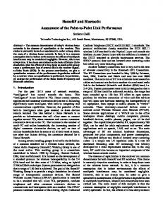
the PC. For video applications, which require connection to devices such as camcorders and video players, the IEEE 1394 [7] is the expected choice. For sharing resources amongst multiple PCs, options such as conventional 10/100 BaseT Ethernet [4], home phone line networks [3], and AC power line networks [9] will exist. (This last option is particularly well suited for many home automation applications where very low data rates are acceptable). As of this writing there are no viable RF networking alternatives at consumer price points that can be used as a networking technology for home networks. The goal of the HomeRF WG is to fill this void2. The networking vision of the HomeRF WG is shown in Figure 1. The RF technology supports both a network of isochronous clients that are slaves to the main home PC, and a network of asynchronous peer devices that is effectively a wireless Ethernet. In most cases the system contains a Connection Point (CP), which is usually connected to the main home PC via USB. The isochronous clients such as cordless telephones, wireless headsets, or remote I/O devices to the home PC (a consumer Personal Information Manager or PIM) are always bound to the CP which assigns them guaranteed bandwidth for bounded latency communication. For asynchronous communications between devices the CP is not absolutely necessary. Asynchronous peer devices can communicate with each other directly and the main home PC is just another peer device.
Up to 128 Plug-and-play with tight integration with TCP/IP and PSTN Family Communications – advanced messaging system etc. Entertainment/creativity – interactive games etc. Home Control – home security, baby monitoring, etc. Resource Sharing – Internet, printers, file sharing etc. Reuse available technology, and reduce component cost wherever possible
Table 1: Translation of key requirements emerging from market survey to design decisions
II
Vision and Usage Scenarios
The HomeRF WG sees SWAP-CA as one of several connectivity options in the home of the future. The relationship of SWAP-CA with other connection options is shown in Figure 1. In this scenario the main home PC is linked to an Internet gateway that might be a 56K, xDSL, or cable modem. This link may be a simple cable, a wired network connection, or a wireless SWAP-CA network connection. This main home PC would likely have a variety of built-in or peripheral resources such as a printer, a scanner, a CD drive, a DVD drive, etc. For most home PCs today and looking forward, it is likely that the Universal Serial Bus (USB) [6] would be the bus of choice for many peripherals that do not need to be mobile or remote from
Figure 1: HomeRF WG’s vision for Home Networking We now describe three distinct application areas that can directly benefit from the technology built by the HomeRF WG. Our first example is a PC-enhanced cordless telephone. Today there are no standards-based digital cordless telephones for consumer use in the United States of America (US) and interoperability of multiple vendors is not there. SWAP-CA defines a new standard for interoperable digital cordless telephones both in the US and globally. Furthermore, the SWAPCA specification includes a standard method for connecting the 2
Very Fast Infrared [8] at 16 Mb/s is a reasonable “no-cable” choice for short distance, line-of-sight communications.
2
cordless telephone to the home PC software applications. Thus many new enhanced features are possible. For example, for an inbound call, the caller ID information is sent to a PC application that looks up the caller’s name and then routes the call to a specific handset instead of another number. For an outbound call, the PC interprets a spoken destination name (e.g. “Call Victor”) through voice recognition, then depending upon the date/time determines the most likely number to reach the called person, and finally routes the call using the lowest cost option available at that time (e.g. using IP telephony). The handset could be used to pick up voice mail selective to the user from the home PC call center. With voice synthesis the handset could also be used to “listen” to e-mail. With more sophisticated application software, the handset could achieve PIM functionality by using voice or keypad I/O to store lists (i.e. “Add 3 quarts of milk to my shopping lists”) or control home automation features (i.e. “Turn the temperature up 3 degrees”). All of these and undoubtedly much more creative features are possible because of the standard interoperable method of connecting to the home PC. The cordless handsets themselves are slightly different but not substantially more complex or expensive than the existing “dumb” cordless handsets sold in multi-million unit volume today. A second example is a mobile viewer appliance. This could take many forms but fundamentally consists of a color LCD display (like that of a notebook computer) with some limited input device (such as a pen) and a SWAP-CA radio network connection. Such a device could be either an extension of the home PC (like an X-terminal or Terminal Server Client) or simply a web-browsing extension of an Internet gateway. In either case the viewer communicates entirely through receiving and sending TCP/IP packets. The third of many potential applications is resource sharing amongst multiple PCs in the same home. The resource to be shared could be a high quality printer, a back-up storage device, a file server, or an Internet connection. Clearly these resourcesharing applications have received considerable attention from other home wiring-based networking alternatives. It is important to note that the market for HomeRF is not strictly multi-PC homes. Any home equipped with a modern home PC or an Internet gateway is a candidate for compelling mobile devices enabled by the SWAP-CA specification. Consider for example handheld devices that allow multi-player gaming. Thus, SWAP-CA is a hybrid in several ways; it is clientserver between the CP and voice devices, but is peer-to-peer between data devices. The interactive voice transactions are circuit switched, but the asynchronous transactions are packet switched. It is precisely this richness that gives SWAP-CA the capability to be used broadly in the home; it is not designed to support hundreds of users doing similar things in an enterprise, but rather the variety of applications that occur in a residential setting. In the next section we describe the different devices types, the network configurations in which these devices operate, and the management and operation of SWAP-CA networks.
III Network Architecture and Operation The SWAP-CA network is designed to operate in the 2.4 GHz Industrial, Scientific and Medical (ISM) band. The 2.4 GHz band is an unlicensed frequency band that is available all over the world, and so SWAP-CA devices can operate globally. The standard is unique in the way it combines ETSI Digital European Cordless Telephony (DECT) standard [10, 11,12], for carrying time-sensitive real-time traffic such as interactive voice, and IEEE 802.11 [14] and OpenAir [15], for carrying traditional data networking traffic such as file transfer. We now describe the different types of devices that can exist in a SWAP-CA network along with their key operational features.
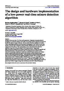
A DEVICE TYPES There are four types of devices that can operate in a SWAP-CA network. These are: 1. Connection Point (CP), which is the gateway between a SWAP-CA device, the PSTN, and a PC (possibly connected to the Internet). 2. Isochronous node (I-node), which is a voice-centric device such as a cordless phone and a walkie-talkie. 3. Asynchronous node (A-node), which is a data-centric device such as a handheld notepad and a personal digital assistant (PDA). 4. Combined Asynchronous-Isochronous node (AI-node) The CP can either be a separate device connected to the main home PC typically via the USB connection or can be an integral part of the PC. It can also have a direct connection to the PSTN. The CP is capable of performing data transfers to and from SWAP-CA devices using both a contention-based and a contention-free protocol (Section IV). When configured to do so, it can provide power management services to both A-nodes and Inodes (see Section IVC). Figure 2 (a) shows an example of a typical SWAP-CA network consisting of two A-nodes, one I-node, and a CP. One of the A-nodes is a power managed display pad whose communications traffic is managed by the PC so it can maximize battery life. Although not shown in this figure, the laptop Anode could also be power managed. As this figure shows, SWAP-CA has a unique ability among networking protocols to mix intense high demand packet traffic with infrequent command and control traffic, and high quality real-time voice traffic. The PC is an integral part of the SWAP-CA system although peer-topeer data networking is available even when the PC is inoperative. Every SWAP-CA device has a 48-bit IEEE MAC address, which is configured by the manufacturer prior to distribution.
B
NETWORK CONFIGURATION
The SWAP-CA network is designed to operate in two basic modes: the network can be configured either as a managed network as shown in Figure 2 (a) or as a peer-to-peer ad-hoc network as shown in Figure 2 (b). In the managed network 3
configuration the network is under the explicit control of a CP, which functions as its gateway to other devices, the Internet, and the PSTN. Furthermore, in this mode the network can simultaneously support both real-time audio traffic, such as interactive voice, and non-real time data traffic such as traditional TCP connections. In the ad-hoc network mode the network provides traditional data networking support only and does not need a CP for proper operation.
I-Node TDMA
Connection Point
Application
CP IWU
Network
A-Node CP
PC
USB
PSTN CSMA/CA
Grandma’s 3 cups flour 1 cup grated chocolate 1 cup sugar 1 stick butter 1/2 cup chopped walnuts minutes. HOME
INDEX
Display pad
Power managed device
A-Node
(a) Managed Network Fridge Pad A-Node
3 cups flour
A-Node
Printer
D DISCOVERY AND CREATION OF NETWORKS CSMA/CA Network Laptop
A-Node
A-Node Television
within its range. This then opens up the possibility that two or more SWAP-CA networks can overlap when devices belonging to these networks come within range of one another. Scenarios like this are likely to occur in places such as an apartment complex where every apartment has its own SWAP-CA network but since the apartments are close to one another devices in one apartment are within range of devices in a neighboring apartment. Usually overlapping SWAP-CA networks do not interfere with each other because the physical layer of the SWAP-CA network uses Frequency Hopping Spread Spectrum (FHSS) modulation for transmission of packets. Since different networks are generally not synchronized and they use different frequency hopping patterns, the probability of interference between overlapping networks is low. Still because there is a small finite probability that neighboring networks can sometime hop on to the same channel, SWAP-CA defines a 24-bit Network Identifier (NWID). The NWID is used to prevent “promiscuous” reception of packets from neighboring networks. Devices having the same NWID are part of a logical network and the NWID is present as part of every data packet in the network; devices only accept those packets that contain the NWID of their private network. Thus, the NWID is used to separate the different overlapping virtual networks located in the same area of coverage. Depending on its configuration a node may either use the NWID that is explicitly assigned to it by the user or alternatively derive a NWID from its MAC address. For an existing network new nodes can learn the NWID as they join the network. For reasons just described, configuring the NWID explicitly is the recommended option to avoid the problem of nodes learning the NWID of neighboring networks and joining those. In the following sub-section we describe how nodes join an existing network and create a new one using a derived, learnt, and explicitly configured NWID.
DVD/ VCR
(b) Peer-to-Peer Ad hoc Network
Figure 2: SWAP-CA network topology flexibility It is possible for two or more SWAP-CA networks to coexist at the same time even when they are within range of one another. This is explained in the following sub-section.
C MULTIPLE OVERLAPPING VIRTUAL NETWORKS There are certain characteristics of RF networks that make them unique. For example, RF signals are not restricted to well-defined boundaries; consequently, a RF node can “hear” other RF nodes operating on the same frequency when they are
When a SWAP-CA node is turned on it immediately enters into a network discovery phase in which it tries to determines if another node or CP is present within its range and if a network already exists that it can join. The node accomplishes its discovery phase by operating in a passive scanning mode. In the passive scan mode the node listens on every channel3, within its operational frequency band, for a specific amount of time, greater than a single superframe (see Section IV). “Listening” on a channel is accomplished by the physical layer which forces the node to hop on a known scan pattern which is a good spread of the hopping patterns on all the channels of the network. During a scan the node receives all network packets regardless of the NWID or destination address. These packets are analyzed by the node’s MAC management module and a decision is made on whether or not to join the network. The scan can be terminated as soon as the first network is found or when the management module so determines. When a network is found the node synchronizes to the network by setting its hopping pattern to the 3
The device has to conform to the rules of the geographic region it is operating in. For example, in North America and Europe the number of channels the MAC hops over is 75, in Japan it is 23, in France it is 35 and in Spain it is 27.
4
discovered network’s hopping pattern, and by recording the network’s NWID. The synchronization information is available on every data packet on the network and is used by the “joining” node to set its own parameters. When the network identifier is known, a SWAP-CA node joins the known network by scanning all the channels for a specific NWID and then by locking-on to the channel on which it finds the NWID. The scanning procedure is terminated as soon as the sought after NWID is discovered. In case the node does not find a network with the particular NWID, it can either give-up or start its own network. To start its own network, the node randomly selects an available hopping pattern, records the NWID as the network identifier, and starts transmitting synchronization signals. It is noted here that not all nodes are allowed to create a network. Specifically, a CP can create a managed network and an A-node can create a peer-to-peer adhoc network. I-nodes do not create their own network. In a managed network the CP is responsible for transmitting synchronization information, whereas in an ad hoc network all A-nodes participate in synchronization. A-nodes share responsibility for beaconing by adding a random back off to the scheduled ad-hoc beacon transmission time. The synchronization information4 contains the network’s hopping pattern and the dwell time5 and is transmitted as part of the beacon signal. When there are two or more devices in the network that are capable of CP functionality, the first one to join/create the network becomes the Active CP while the remaining ones become Passive CPs. In case a Passive CP does not hear 50 consecutive beacons from the Active CP, it assumes that either the Active CP has gone off-line or has moved out of range and consequently creates its own network by transmitting synchronization information. If 100 or more simultaneous beacons are missed by the A-nodes in the network, they start operating the ad hoc network synchronization operation and create an ad hoc network. The entire process of scanning followed by either joining or forming a new network can on an average take about 1.5 seconds.
provides security and privacy is clearly needed and should be part of any wireless networking standard. Data privacy and authentication in a SWAP-CA network is accomplished by using a well-established shared-key encryption algorithm. Notably, all I-nodes follow the per-session key security model defined in the ETSI DECT specification [12]. The authentication process in this model is split into a key generation process and the encryption process. The purpose for splitting this process is to support roaming of handsets between DECT base stations. SWAP-CA defines its authentication process in terms of the DECT security model. A node indicates that it supports encryption to the destination node as part of the capability exchange process. Data packets are encrypted only if the destination node can decrypt the message. The encryption algorithm takes a 56-bit key and a 32-bit initialization vector and uses these to convert unencrypted data (called plaintext) to encrypted data (called ciphertext). The initialization vector is a combination of the packet sequence number and a hash of the 48-bit MAC address of the source node. The sequence number keeps track of the number of packets the node has encrypted and prevents against replay attacks. A Magic Number, a byte containing all zeros, is appended to every packet before encryption to allow the receiver to check, as it decrypts the packet, whether or not it has the right key. All A-nodes in the SWAP-CA network share a single common 56-bit key. The key may be entered though a Management Information Base (MIB)6 or computed dynamically. A property of this algorithm is that the output ciphertext is of the same length as the input plaintext and the encryption algorithm is symmetric (i.e. decryption performs the same process as encryption). The core of the encryption algorithm is common to both asynchronous and isochronous data services. All multicast and broadcast traffic is sent unencrypted since there is no guarantee that all A-nodes within range support the encryption option.
E
Since wireless networks generally have limited bandwidth, an often-stated design goal for these networks if to build a system that is bandwidth efficient. One way to improve bandwidth efficiency is to compress the data before transmission. Data compression in a SWAP-CA network is optional and is left to the designer’s discretion as it provides a trade-off between battery longevity and bandwidth. With compression, nodes can transmit more data in a given amount of time than nodes that do not compress their data, however, compression consumes power and therefore contributes to battery drain for portable devices. Another problem is that data compression involves the reduction of redundancy in the data. Consequently, any corruption of the data is likely to have severe effects and be difficult to correct. The point is that the network operator has to consider all these tradeoff before deciding whether or not to enable compression.
AUTHENTICATION AND PRIVACY
As discussed in Section C, RF signals are not restricted to well-defined boundaries and consequently, unlike a wired network an RF wireless network is difficult to secure. The transmission medium is open to anyone within range of the transmitter. Even when the physical layer of the network is based on spread spectrum communication and different networks use different hopping patterns the system is insecure as it is relatively easy for a malicious user to scan all channels and determine the hopping pattern and NWID of the target network. Thus, neighbors who receive RF signals from each other can conceivably “listen-in” on each other’s conversations and intercept each other’s data packets. This is clearly undesirable. Consequently, an encryption mechanism that
F
COMPRESSION
4
A beacon signal is a broadcast packet transmitted by a node (a CP in a managed network) periodically. It contains information that the network devices need for proper operation within the network. 5 The dwell time is equal to the superframe period
6
A MIB contains information that is used to manage the operation of a SWAP-CA node. This information can be used by higher layer protocols to manage the node as well.
5
MAC Function
CP
A-node
I-node
AI-node
Synchronization within a managed network Synchronization within a ad-hoc network Power Saving A-node power support Power Management for multicast
M O O M
M O O O -
M O -
M O O O -
Connection Management
M
-
M
-
TDMA access CSMA/CA access
O M
M
M -
M M
Service-slot access
-
-
M
O
CP assertion
M
-
-
-
Table 2: MAC behavior depends on device type (M – mandatory, O – optional) • Built-in power management capabilities for both Isochronous and Asynchronous nodes. • Multiple levels of data security is provided – None / Basic (FHSS + NWID) / Robust (FHSS + NWID + 56-bit stream cipher) • Support for multiple networks in the same physical area with a 24-bit network identifier.
The recommended compression algorithm for a SWAP-CA network is a lossless compression algorithm that uses a combination of the LZ77 algorithm [16] and Huffman coding [17]. The efficiency of this algorithm is comparable to the best currently available general-purpose compression methods. The data can be produced or consumed, for an arbitrarily long sequentially presented input data stream, while requiring very few resources in terms of processing power and memory [18]. As with encryption, compression is used only if the source node determines that the destination node is able to decompress the message. This is determined during connection-setup and capability exchange time. Compression is not used for multicast and broadcast traffic. We now discuss in detail the medium access control mechanism that makes SWAP-CA unique, and a compelling technology for home networks.
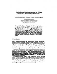
Figure 3 illustrates the protocol framing when the network is configured as a managed network7. SWAP-CA defines a superframe, which is a periodic division of time. A superframe contains two contention-free periods (CFP1 and CFP2) and a contention period. The channel access mechanism used during the contention-free periods is TDMA and during the contention period is CSMA/CA. The duration of the superframe is fixed and a synchronization mechanism allows the nodes of the network to agree on the superframe timing. SWAP-CA devices employ a frequency hopping spread spectrum modulation for transmission of packets (details in Section V). All nodes in the network hop together using the same hopping pattern and they hop to a different frequency at the start of every superframe. By hoping to a different frequency channel every superframe period, the dwell-time of the devices on a portion of the spectrum in which there may be high interference is reduced. This in turn reduces packet errors and packet loss, thus improving the overall throughput and reliability of the system. The start of a superframe is marked by a Connection Point Beacon (CPB) signal. The CPB is used for multiple purposes including: (1) maintaining network synchronization, (2) controlling the format of the superframe, (3) managing the network during the contention free period by indicating when each node should transmit and receive data. The CPB can include a list of active voice connections (and therefore slot assignments), retransmission slot assignments for the current superframe, connection status information, and paging information, and (4) providing power management services for Isochronous and
IV Medium Access Control The SWAP-CA medium access control protocol is derived from the ETSI DECT standard [10], [11], [12] and from the popular Wireless LAN standards such as IEEE 802.11 [14]. It is optimized specifically for the home environment. The MAC is designed to work over, and to take advantage of the frequency hopping radio subsystem. It includes a Time Division Multiple Access (TDMA) service for delivery of realtime isochronous data, and a Carrier Sense Multiple Access with Collision Avoidance (CSMA/CA) service for delivery of asynchronous data. The MAC’s behavior depends on the devices that are in use in the network. Table 2 contains the functionality supported by the MAC for different device types. Some of the highlights of the MAC protocol are as follows: • Simultaneous support for both voice and data traffic using a unique combination of TDMA and CSMA/CA access mechanisms. • Support for 4 high quality, 32 Kbps Adaptive Differential Pulse Code Modulation (ADPCM) voice connections. • Data throughput of about 1.6 Mbps.
7
In ad hoc networks the SWAP-CA MAC reduces to a CSMA/CA MAC.
6
Service Slot
Transmit Downlink
D1
D2
D3
D4
B D3
D4
Hop
U1
U2
U3
U4
CFP2
CFP1
Hop
U3
U4
Contention period CSMA/CA access mechanism
D4
D3
Hop
D2
D1 Hop
U4
U3
U2
U1
Superframe
Uplink
Retransmission 1
Connection 1
B - Beacon Dn - Downlink slot Un - Uplink Slot CFP1 - Contains two slots per connection for data that requires retransmission CFP2 - Contains two slots per connection, one for downlink data and the other for uplink data
Figure 3: SWAP frame description Asynchronous nodes to maximize the battery life of portable devices (see Section C). Slot assignment and synchronization information does not change on a per frame basis, so if a node misses a beacon it uses the information contained in the most recent valid beacon. All connection and paging status requests and information are repeated until the receiver acknowledges them. Real-time voice traffic is tightly integrated into the MAC. This is discusses in the following sub-section.
A VOICE ENCODING AND TRANSMISSION The SWAP-CA standard specifies a 32 kbps ADPCM codec, defined in CCITT Recommendation G.726 [13], as a baseline voice encoding mechanism. I-nodes process 20 msec. segments of 14-bit linear PCM audio samples, sampled at 8 KHz. These samples are companded and encoded to a sequence of 4-bit ADPCM code-words before being packetized and queued for transmission in a chronological order. Encoded voice packets are transmitted during the contention-free period The contention free periods are divided into a number of pairs of fixed length slots, two per voice connection. The first slot in each pair is used to transmit voice data from the CP to a node (downlink) and the second is used to transmit voice data from a node to the CP (uplink). CFP2 at the end of the superframe is used for the initial transmission of the voice data, whilst CFP1 at the start of the superframe is used for the optional retransmission of any voice packet which was not received or was incorrectly received in the previous dwell. Each voice packet transmitted by an I-node includes in the packet header a piggyback acknowledgement (ACK) of the last voice data message received by the node. i.e. in the uplink packet the voice node ACKs the downlink packet sent by the CP. This allows the CP to determine prior to a hop which voice data transmissions were lost, and determine whether or not retransmissions are required. Retransmissions are advertised in the beacon at the start of the next superframe; each voice data packet is only retransmitted once.
The time between the first voice packet transmission during CFP2 and its re-transmission in CFP1 is a function of the voice codec and is fixed at 20 msec. This provides an acceptable performance with respect to latency. The length of the dwell period is equal to a single voice data message containing 20 msec segments of ADPCM data (640 bits), which is equivalent to an extended DECT Bfield plus 56 bits of control data, and equivalent to the DECT A-field plus some additional addressing information [11]. With a 20 msec. superframe, SWAPCA can support up to 4 voice connections simultaneously with full re-transmission possibility. Robustness against interference is achieved by choosing CFP2 for the initial packet transmission and the following CFP1 for any retransmission. Thus, the system provides both frequency and time diversity. This is particularly important given the potentially noisy environment in which the protocol operates. At the end of CFP1 there is space reserved for a Service Slot. I-nodes use the Service Slot is to request a connection form the CP. Since there is only one Service Slot it is possible for two or more modes to transmit at the same time and for their transmission to collide. Each management message is explicitly, acknowledged by the CP in the CPB, and if there is no ACK a node performs a random back-off across a number of dwell periods before re-sending the message. The average time to connect can vary since CFP1 varies, depending on number of retry slots. CFP2 is more constant, but always depends on the number of active handsets. Normally the connection setup will succeed at the first possibility. Subsequent attempts to use the service slot will take place on average 160ms apart CFP1 varies, depending on number of retry slots. CFP2 is more constant, but always depends on the number of active handsets. Normally the connection setup will succeed at the first possibility. Subsequent attempts to use the service slot will take place on average 160ms apart.
7
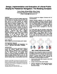
B DATA TRANSMISSION For data traffic a CSMA/CA access mechanism is used during the contention period of the superframe. With this scheme, the protocol provides efficient data bandwidth even with concurrent active voice calls. Peak effective user throughput of up to 1 Mbps is possible under lightly loaded conditions in the 1.6 Mbps mode. Furthermore, data transfer between nodes can occur even when 4 voice calls are active simultaneously. The CSMA/CA protocol attempts to avoid collision by adopting listen-before-transmit (LBT) etiquette -sensing transmissions on the radio medium and starting transmission when there is no such activity. The mechanism is similar to Ethernet (IEEE 802.3 [4]]), enabling easy integration with an existing TCP/IP protocol [19] stack within a host platform; the main difference with Ethernet is the slotted contention mechanism and the addition of MAC level ACK of unicast packets. Figure 4 illustrates how the medium is accessed during the contention period.
Slot 1 Slot 3 Slot 2 Slot 4
Medium Busy
SIFS
Slot Time
Attribute Superframe Duration SIFS DIFS Maximum beacon period duration TDMA slot-pair duration (2 * TDMA slot duration + SIFS) Maximum unicast MSDU length Maximum time to spend transmitting/receiving a data packet Maximum Contention Window Size Minimum Contention Window Setting Persistence of events in the CP beacon Time after which node can go into power saving mode Maximum time between checking CP beacons by a PS-node Maximum time between power management requests Maximum number of dwells I-nodes backoff for service slot
ACK
Packet Transmitted
SIFS=142 us Slot Time = 167 us DIFS=309 us
the node transmits the message. Whenever the medium is busy the countdown is suspended and only resumes when the medium has been free for a DIFS. This back-off mechanism reduces the probability of collision and performing a back-off before transmission ensures that responses from multiple nodes responding to a broadcast message on an otherwise idle network do not all collide. If a retransmission is required because of a collision or transmission failure the size of the collision window is increased from an initial value of 8 exponentially up to a maximum 64 to avoid congestion. Typical values for parameters used by the MAC are shown in Table 3.
SIFS
DIFS
• Sender selects a slot (backoff counter) and then decrements the counter whilst the medium is clear • Medium must be free for a DIFS period before the backoff counter is decremented. • Example shows transmission of a packet in slot 5.
Figure 4: CSMA medium access procedure Access to the wireless medium is controlled through the use of inter-frame spacing (IFS) time intervals. The IFS intervals are mandatory periods of idle time on the transmission medium between frames. Two IFS are specified in the standard: Short IFS (SIFS) and DIFS (the name is taken from the IEEE 802.11 standard [14]). SIFS is the time it takes for the PHY layer to get ready for a transmission or reception. It is constrained by the physical layer’s (PHY) performance and dictates the minimum time separating two independent MAC transmissions on the channel. Slot-time (or SlotDuration) is also constrained by the PHY layer. It is the time taken by the PHY layer to estimate the state of the wireless medium as idle or busy with certain accuracy. DIFS is one SlotDuration longer than a SIFS period. When the channel is free for a DIFS time period it indicates to the node that the previous data exchange is complete and that it may contend for the channel. The access procedure is designed to provide fair access to the wireless channel for all nodes by using a contention window and back-off counter as shown in Figure 4. Before any node transmits a packet it selects a back-off counter (a number of contention slots) and then starts “listening”. When the medium has been clear for a DIFS period it decrements its back-off counter for each free contention slot. When the back-off counter expires
Typical Value 20 msec 142 usec 309 usec 1278 usec 2364 usec 1500 octets 100 msec. 64 slots 8 slots 3 1 sec 4 sec 60 sec 16
Table 3: Typical values of some attributes used by the MAC layer The basic structure for the MAC data frame exchanged between peers is shown in Figure 5. The Ethertype used in SWAP-CA is compatible with the Ethernet Ethertype and its value is managed by the IEEE. An example of a popular Ethertype, for Internet protocol, is 0x0800. The asynchronous data service supports a MAC Service Data Units (MSDU) with sizes of up to 1500 bytes. All MAC frames are protected by a 32-bit CRC.
DA
SA
Ethertype
SC
MSDU
Status
DA - IEEE 48 bit MAC address of Destination SA - IEEE 48-bit MAC addess of Source Ethertype -16-bit etherytype value SC - Service Contro l(Encryption, compression, data rate) MSDU - MAC Service Data Unit Status - success or expired
Figure 5: Basic MAC frame for the asynchronous data service 8
Reliability of unicast data packets is guaranteed through an ACK/retry mechanism, however it is not guaranteed for multicast data packets. Also, the order of unicast data packets sent between two SWAP-CA nodes is generally preserved. The MAC is not allowed to gratuitously re-order data packets, however re-ordering is possible when the device is in power-saving mode. When there is no CP present, data nodes can create an ad-hoc network in which control of the network is distributed between all the nodes. When there are no active voice connections, the CSMA/CA period expands to occupy the entire superframe, with the exception of the hop and beacon, thus maximizing the network data throughput. The MAC contains special support for saving power. This is explained in detail in the following section.
C POWER MANAGEMENT SERVICES It is a well-understood fact that battery energy is a limited resource that is not expected to increase in potential more than 30% in the near future [20]. Consequently, for portable battery operated devices this resource needs to be used carefully and efficiently. A wireless network transceiver can typically use anywhere from 15 to 30% of the power from a typical portable computer, the display being the only part that consumes more power [21]. Most wireless network interface cards that are in the market today consume close to 12 times the power of a standard 10 Mbps Ethernet card and the battery longevity for wirelessly connected portable devices is reduced by as much as 60%, i.e. from a 3 hour operation down to 72 minutes. It is therefore mandatory for any wireless standard to support power management functions and be power-aware. So, one of the primary design goals that influenced the design of SWAP-CA MAC was to provide power management services. We discuss how this service is incorporated in the standard. Power management can be enabled only when the network is configured as a managed network and the CP is a key component of the power management services in a SWAP-CA network. Both A-node and I-nodes can save power by enabling the power management services within the CP. For I-nodes, the procedure for power management is straightforward. During an on-going connection (e.g., an active voice call) the I-node that has registered with the CP as being a power saving node powers-on, initially only for the duration of the CPB, to receive slot assignment information. It then powers-down until its assigned slots are due. When not in an active connection state, I-nodes, power-up every N dwells, where the system designer chooses N as a compromise between power saving and speed of response to a new connection. In every beacon the CP broadcasts a list, or directory, of the nodes, which have traffic pending for them. Power management for I-nodes is illustrated in Figure 6.
Sender
Connection Point
Receiver
Power Management Service Request
Awake
Request Accepted Data Wake-up Request Sleep Wake-up Notification Wake-up Acknowledgement Wake-up Successful Awake Data Data Data timeout Sleep
Figure 6: Power management of TDMA nodes in a SWAP-CA network For A-nodes the behavior of the power management service depends on the type of packet being transmitted. Figure 7 illustrates the process of sending broadcast messages to power-saving asynchronous nodes. The process is described with the help of an example in which two asynchronous nodes (Node A and Node B) send broadcast packets, and Node C, a power saving node, is a receiver of these packets: (a) Node C powers-up and receives a “dwells-towakeup” counter of 3, which is broadcast in the CPB. The maximum value of the ‘dwells-tobroadcast’ counter is a system design parameter that allows the designer to tradeoff latency, CP buffer size and broadcast reliability against batterylife. The CP maintains a countdown to the next dwell when power saving (PS) nodes would wakeup. (b) Node A transmits a broadcast message, which is received and stored by the CP. (c) Node B transmits a broadcast message, which is received and stored by the CP. (d) Node C wakes up when its dwells-to-wakeup counter reaches 0. It checks the CPB and sees an indication from the CP that packets are available for it and consequently stays powered-up. (e) The CP transmits the buffered broadcast messages during the dwell. (f) Node C receives the broadcast messages and then goes back to sleep mode. Figure 8 illustrates the process for sending unicast messages to power-saving asynchronous nodes. Once again we explain the process with the help of an example: Node A sends a unicast message to Node B which is a power saving node. The wake-up pattern of 9
Step #1: Node C wakes up to check ‘dwells-to-wakeup’
CP re-Broadcasts
CP Buffers Broadcast packets B
Hop
Dwells to broadcast wakeup
Step #4: Node C wakes up to receive broadcast
Connection Point Step #5:
Hop
B
B
Hop
Hop
BP #1
B
BP #1
BP #2 Hop
B
BP #2
3
2
1
n
n-1
Step #3:
Step #2: Broadcast packet
Step #6:
Broadcast packet
Node A
receives Node A & B packets from CP
Node B
Node C
Figure 7: Power management of CSMA nodes for broadcast messages
Connection Point Step #1 PS-node wakes up doesn’t hear ‘wakeup’ so switches off
Step #3 CP sets ‘wake-up’ flag and node address
Step #4 PS-node wakes up, hears ‘wake-up’ so stays switched on
W B
B
B
Hop
Step #2 Sender asks CP to wake-up PSnode
B
Hop
Hop
CPS REQ
SI
Sender hears PS-node wake-up
UP #1
A C K
Hop
UP #2
Step #5 Sender and PS-node transfer data
Node A
A C K
Step #6 PS-node switches off after timeout
Power-Saving Node
(Node B)
Figure 8: Power management of CSMA nodes for unicast messages up flag. Consequently it stays powered on for the dwell. (e) Node B and Node A transfer data using the normal CSMA/CA access method. (f) Node B powers-down after the exchange of final message is complete.
power saving nodes (Node B) is controlled by a ‘wakeup’ flag transmitted in the CPB upon request from the sending node. The example below describes how this feature is used. (a) Node B powers-up, and checks the CPB. It does not see a wake-up signal from the CP, concludes that no packets are waiting for it and powers-down. (b) Node A sends a request to the CP to ‘wake-up” Node B. (c) The CP asserts the wake-up flag for Node B in the CPB. (d) Some time later (dependant on the designer’s tradeoff of power-saving versus latency) Node B wakes up, checks the CPB and receives the wake-
Some general comments follow: The unicast and multicast state machines are independent; consequently, a power-saving A-node can operate unicast, multicast or both types of power-saving procedures. The multicast power management service is completely transparent to the sender; the CP automatically re-sends all multicast packets regardless of their source. A SWAP-CA network 10
may contain both PS and non-PS nodes simultaneously. The CP stores the address of the PS nodes as a list of nodes to which it provides power management service. To guarantee proper network operation, PS nodes periodically re-request power management services from the CP to guard against CP disappearance from the network (when it is stopped, or when a higher functionality CP takes over) and against CP holding on to resources assigned for a PS-node.
V
Physical Layer and Components
The physical layer specification for SWAP-CA was largely adapted from the IEEE 802.11 FH [14] and OpenAir [15] standards with significant modifications to reduce cost while maintaining more than adequate performance for home usage scenarios. The SWAP-CA PHY layer provides the transmission and reception of data packets in the 2.4 GHz ISM band, using a 2-level Frequency Shift Key (2-FSK) [22] modulation scheme, for 0.8 Mbps raw data rate performance, and an optional 4-FSK, for 1.6 Mbps raw data rate performance. Some key features of the SWAP-CA physical layer specifications are: • Transmit power – Up to +24 dBm (or nominally 100 mW-250mW8) • Low power transmit mode (optional) – between 0 and +4 dBm (for portable devices with limited peak current capability) • Receiver sensitivity in 2-FSK (or 0.8 Mbps mode) – less than -80 dBm; in 4-FSK (or 1.6 Mbps) less than –70 dBm • Hopping time – 300 us (to allow conventional synthesizers to be used) • Transceiver turnaround time – 134 us (very easy to achieve with existing synthesizers) • Adjacent and alternate channel filtering – no requirement The combination of the transmit power and the receiver sensitivity represent a typical range that should easily exceed 50 m in most home environments. In the optional low power mode, reliable indoor range is expected to be 10-20 m (which covers the bulk of the interior of most homes). Although the PHY layer design is quite similar to the IEEE 802.11 FH and OpenAir design, the SWAP-CA requirements impose substantially lower cost constraints for three reasons. First, the required sensitivity limit is relaxed by about 10 dB. Second, the greatly relaxed channel filtering specification causes dramatically less inter-symbol interference due to filter group delay variations in the passband. And third, the SWAP-CA packet headers for 4-FSK add a special 8
The nominal transmit power level is defined as the power delivered to the antenna averaged between the start of the first symbol and the end of the last symbol in the physical layer packet header.
training sequence to allow optimum slicing threshold values to be determined for the changing propagation environment. Thus for usage within most homes, the 1.6 Mbps data rate is really available with SWAP-CA and adds virtually no cost to the 0.8 Mbps solution. Although the hopping time is easy to meet, the transceiver turnaround time creates challenge for many conventional RF transceiver architectures and components. This low transceiver turnaround limit is essential for SWAP-CA to provide low latency performance in a mixed voice and data network in the presence of microwave ovens and other interference sources. Fortunately, increasing levels of integration and speed in Complementary Metal Oxide Semiconductor (CMOS) circuits now make it possible to build very fast switching channel synthesizers capable of this requirement by adapting technology previously used in precision instrumentation. In fact, the entire SWAP-CA PHY-layer specification has been written specifically to accommodate very low cost, single-chip implementation in CMOS technology. A typical system partitioning is shown in Figure 9. For many of the digital devices envisioned by the HomeRF WG, the digital MAC baseband portion of the component solution can be integrated into a large Application Specific Integrated Circuit (ASIC) already in the device. At ~30K gates for the SWAP-CA data core, this is extremely low cost in the sub-0.25 um CMOS era. The modem functionality can interface to the digital baseband via a very simple serial interface (with no analog quantities). The modem and RF functionality can all be integrated into a single mixed-signal CMOS Integrated Circuit (IC) as shown because of the specific technical requirements on filtering and modulation chosen by the HomeRF technical team. Note that it probably does not make sense to integrate the RF front-end functionality such as the low-noise amplifier, the power amplifier (if present), the antenna switches and the band-select filter onto the CMOS IC even though technically feasible. This is because the semiconductor die area for the front-end functions is typically much less than 5% of the rest of the modem (hence low cost already) and the overall power consumption performance is driven largely by optimizing these functions in detail.
Figure 9: Partitioning of RF Modem and Digital MAC Component Sections
11
With such high levels of integration and optimized front-end, the RF modem section overall cost in multimillion unit volume should be well below $10 (similar to the situation today with DECT equipment) while the digital MAC section approaches “zero” other than IP royalties. Note that while this seems extraordinarily low compared to today’s common perception of RF data being $100’s per node, it is still very expensive compared to the very low cost of IrDA transceivers or USB controllers. Thus cost remains a significant issue to making HomeRF a “throwaway” item in every electronic device. But consumers have consistently shown with voice that they will pay extra for personal mobility. Even today, cordless phones are significantly more expensive than corded phones yet much more popular. If consumers begin to value mobility within the home for Internetbased content the way they do today for PSTN-based content, then the present cost projections for enabling SWAP-CA in devices should not be a serious barrier. Table 4 contains some typical values used by the SWAPCA PHY layer. Attribute
Typical Value
Time to sense the channel Time to stabilize on new frequency Rx/Tx turnaround time Time to trasmit single PHY symbol
27 usec 300 usec 134 usec 1.25 usec
system. Information about the device not covered in the standard programming interface is exposed by a private interface that may be provided by the hardware vendors to application writers as needed. Windows defines a Network Device Interface Specification (NDIS) [24] for programming networking hardware. The NDIS software library, which is the implementation of this specification, performs many of the functions that are common to device drivers of networking hardware including synchronization, device mapping, interrupt handling, event logging, etc. Furthermore, it provides a standard interface for higherlevel protocols and applications, which can be agnostic of the underlying hardware. Manufacturers of network adapters write a NDIS miniport driver that provides functionality specific to their hardware. Miniports of a given media type can be used by higher-level protocols knowledgeable about that media type with no further modifications. Figure 11 illustrates how the various software modules fit together. The shaded blocks are provided as standard part of the operating system and the hardware vendor writes the miniport device drivers. Miniport drivers that are written to conform to the NDIS specification are guaranteed to work with the Windows operating system. Application
Application
Table 4: Typical values of some attributes used by the PHY layer
Due to the wide scale availability of the Microsoft’s Windows operating system and its use as a de-facto standard operating system for home PCs, the HomeRF WG sought to streamline operation of SWAP-CA devices on these systems. We now briefly describe how SWAPCA devices operate in the context of a main-line operating system. Legacy Application
Voice Application
Asynchronous Data driver
Isochroous Data driver
WinSock + Win32 API
User-level
VI Software Architecture
Private Interface
Kernel IPX
TC
Native media-aware
Network Device Interface Specification (NDIS)
NDIS (connectionless) miniport
SWAP-CA Hardware
MIB Access
SWAP-CA node hardware
Figure 10: Interfaces exposed by a SWAP-CA device. A SWAP-CA enabled node connected to a PC exposes three distinct types of interfaces: asynchronous data, isochronous data, and management. Figure 10 illustrates the three types of interfaces. The interface exposed to legacy data-centric applications and voice application is a standard part of the Windows operating
Figure 11: SWAP-CA A-node driver architecture NDIS exports two distinct interfaces – a connectionless interface (used by broadcast media such as Ethernet) and a connection-oriented interface (used by media that have explicit connections between endpoints, such as in Asynchronous Transfer Mode [25] network connections). Hardware manufacturers who produce Anode SWAP-CA devices are required to write a connectionless miniport device NDIS driver only that declares itself as a member of the Ethernet media type. To higher-level protocols and applications, SWAP-CA A12
nodes are then indistinguishable from normal Ethernet adapters, allowing Ethernet-knowledgeable applications to immediately function with SWAP-CA devices. This inheritance of applications was an important design goal. Hardware manufacturers who produce I-node devices create a miniport driver that declares itself as a member of the Ethernet media type and exposes a connectionoriented interface, not the connectionless interface traditionally used. In addition to the basic miniport functions, I-node drivers provide call management functions such as those required for setting up and terminating voice calls. Call control of SWAP-CA I-node adapters is managed by the Telephone Application Programming Interface (TAPI) [24]. TAPI is a simple, generic set of objects, interfaces, and methods for establishing connections between devices; TAPI communicates with NDIS via a TAPI service provider also called a TAPI proxy. TAPI applications set up, control, and tear-down calls on SWAP-CA devices via the TAPI proxy. The various software modules are illustrated in Figure 12, once again the shaded region are part of the most recent version of the operating system. Telephony Application TAPI User level
TAPI Service Provider
DirectShow Streaming
Voice data TAPI proxy
RCA
Call control Information
Call Manager Kernel level
NDIS Miniport
NDIS SWAP-CA Hardware Figure 12: SWAP-CA for isochronous service driver architecture Some applications may wish to stream voice conversations between SWAP-CA adapters and another adapter within the PC in real-time. An example scenario is that of a SWAP-CA I-node (a cordless phone) user communicating with a SWAP-CA Connection Point, which is part of the PC. This connection is forwarded on to another adapter in the PC, possible a modem attached to a phone line or a sound card attached to speakers and a
microphone. To implement this application, the voice data is streamed between the SWAP-CA adapters via the DirectShow Streaming module [24]. The DirectX architecture was designed to accommodate real-time traffic within a PC. A DirectShow filter is plumbed from the data source (in this case, the SWAP-CA adapter) to the data sink (the modem or sound card). Voice streams coming in via NDIS are redirected to the Raw Channel Access (RCA) filter, which in turn sends them into DirectShow. The RCA filter is part of the operating system so connection-oriented miniports are automatically voice stream-enabled.
VII Positioning with Other Technologies Comparisons are generally always controversial, but we still present Table 5, which compares the features of various similar home networking technologies. In our opinion, several of these the technologies included are more complementary than competitive. The HomeRF and HomePNA [3] technologies are very synergistic for home electronics manufacturers because they share much networking infrastructure even though the physical media are quite different. In both cases, there are simplified “single-cell” networks where voice to the PSTN and data to the Internet can be combined simultaneously. For in-room (or in-car) pointpoint or point-multi-point connectivity, the proposed Bluetooth protocol [27] and the industry-proven IrDA standards (with over 60 million units shipped) [8] are most appropriate. Amongst these two technologies, Bluetooth offers greater physical convenience in its usage model as it is not line of sight and can pass through minor obstructions but the IrDA standards are very hard to beat by any radio technology in terms of their data rate, cost or physical size. The few competitive wireless networking options that are either available today or will be available in the near future have been designed primarily for the enterprise market. For example, the IEEE 802.11 [14] and HIPERLAN [23] are effectively wireless Ethernet technologies developed for the enterprise network. Both support multiple cell hand-offs and roaming so entire campuses may be covered. These technologies permit users to trade data-rate with cost and power consumption. Note that while HIPERLAN is legal in Europe only, similar technologies are likely to develop in the US where the Unlicensed National Information Infrastructure (UNII bands) located at 5.15-5.35 GHz and 5.725-5.825 GHz has recently been created [26]. Note that in Table 2 the standby current refers to the average current draw for the transceiver portion of portable devices while retaining full network availability for the given technology.
13
Properties
HomeRF [2]
Bluetooth [27]
IEEE 802.11 FH [14]
HomePNA [3]
IrDA [8]
HIPERLAN [23]
Operational Spectrum
2.404 – 2.478 GHz
2.402 – 2.480 GHz
2.40 – 2.4835 GHz
Phone Line
Infrared, 850 nm
Physical layer
FHSS, 50 hops/sec, 2FSK & 4FSK CSMA/CA + TDMA 0.8 and 1.6 Mbps < 50 m < 1 mA & ~ 300 mA via TCP/IP via IP & PSTN CRC / ARQ Type 1
FHSS, 1600 hops/sec, GFSK
FHSS, 2-FSK, 4FSK, …
?
Optical
51.15-5.3 GHz (and 17.1 – 17.3 GHz) Differential GMSK
Master-slave, Polling 0.721 Mbps
CSMA/CA with RTS/CTS 1 and 2 Mbps
?
Polling
EY-NPMA
10 Mbps
23.5 Mbps
< 10 m < 1 mA & ~ 60 mA via PPP via IP & Cellular 1/3 rate FEC,, 2/3 rate FEC and ARQ Type 1 - NA -
< 50 m ~ 10 mA & ~ 400 mA via TCP/IP via IP
Phone jack ?
16 Mbps (VFIR) ~1m < 10 uA, & ~300 mA via PPP via IP
via TCP/IP via IP
?
BCH (31,26)
- Yes -
- NA -
- NA -
Yes
Directory based
- No -
- No -
None
None
- Not specified Directory based < 10 msec for voice 32 Kbps ADPCM
Channel Access Peak Raw Data Rate Range Standby & Peak current Data Traffic Voice Traffic Error Robustness
Mobility support
- NA -
Energy Conservation Guaranteed latency
Directory based < 20 msec. for voice 32 Kbps ADPCM
Speech Coding
Security
Communications Topology Price Point (estimate)
CRC / ARQ Type II
via TCP/IP via IP & PSTN ?
< 30 m > 2A
- NA -
-not specified-
56-bit Shared-key encryption Peer-to-peer, MS-to-BS
64 Kbps with CVSD/logPC M Stream cipher algorithm
- not specified - not specified -
64-bit shared key encryption
?
?
?
Peer-to-Peer, Master-slave
Peer-to-peer, MSto-BS
Broadcast
Masterslave
Medium
Medium
Medium/High
Medium /Low
Low
Peer-to-peer, multi-hop, MS-to-BS High
Table 5: Comparison of SWAP-CA with other connectivity options
VIII Future of HomeRF The HomeRF organization is discussing a variety of future derivatives from the initial SWAP-CA specification. One possible derivative is simply to increase the data rate within the existing the 2.4 GHz band while retaining full backward compatibility with the initial specification. The group is presently considering options in this regard that would scale SWAP-CA to 10 Mbps in the 2.4 GHz band. In addition, HomeRF is also developing two major new Market Requirements Documents. The first is SWAP-MM (for multi-media), which is looking at true video applications within the home enabled by wireless networking. This work will
likely proceed to a formal technical proposal for the 5 GHz band. It is unclear at this point whether the SWAPMM specification can ever be as near global as the 2.4 GHz SWAP-CA. As with the SWAP-CA case, achieving consumer price points with a SWAP-MM solution will be critical. The other direction HomeRF is considering is an ultra-low cost version called SWAP-lite that could be developed to be interoperable with future SWAP-CA devices while achieving much lower price and power consumption points. Keyboards, mice, joysticks, remote controls, toys, etc. are the products that might use SWAPlite. Clearly such a system overlaps in capability with infrared technology, which sets a tough measure to compete with in terms of price/performance. 14
Portable Computers,” Proceedings of the IEEE, Vol. 83, No. 4: 636-658 (April 1995)
References [1] The HomeRF Working Group, http://www.homerf.org [2] HomeRF Technical Committee, “Shared Wireless Access Protocol, Cordless Access (SWAP-CA) Specification,” Revision 1.0 (January 1999); Revision 1.1 (May 1999); Revision 1.2 (October 1999) [3] Home Phoneline Networking Alliance (HomePNA), http://www.homepna.org/ [4] American National Standards Institute, ANSI/IEEE, Std. 802.3-1985, IEEE Computer Society, New York, New York, (1985) [5] IEEE 802.3 Carrier Sense Multiple Access with Collision Detection, New York, IEEE (1985) [6] Universal Serial Bus, http://www.usb.org/ [7] IEEE 1394 - High Performance Serial Bus Bridges Working Group, http://www.ieee.org/groups/1394/1
[22] H. Taub, D. L. Schilling, Principles of Communication Systems, Second Edition, McGraw-Hill Book Company, 1986 [23] ETSI RES 10, "Radio Equipment and Systems (RES): High Performance Radio Local Area Network (HIPERLAN); Function Specification," January 1995 [24] Microsoft Corporation. Microsoft Windows NT 5.0/WDM 1.1 Driver Development Kit, 1998. [25] The ATM forum, http://www.atmforum.org [26] FCC, ET Docket No. 96-102 “Amendment of the Commission's Rules to Provide for Operation of Unlicensed NII Devices in the 5 GHz Frequency Range” (January 9, 1997) [27] J. Haartsen, and S. Mattisson, “BLUETOOTH: A New Radio Interface for Ubiquitous Connectivity,” Proceedings of the IEEE (this issue)
[8] Infrared Data Association, http://www.irda.org/ [9] D. Radford, “Spread Spectrum Data Leap through AC Power Wiring,” IEEE Spectrum, (June 1994): 49-55 [10] ETS 300 175-1. DECT Common Interface, Part 1: Overview. Second Edition, (September 1996) [11] ETS 300 175-3. DECT Common Interface, Part 3: Medium Access Control Layer. Second Edition, (September 1996) [12] ETS 300 175-7, DECT Common Interface, part 7: Security Features. Second Edition, (September 1996) [13] CCITT Recommendation G.726 40, 32, 24, 16 kbit/s Adaptive Differential Pulse Code Modulation (ADPCM). Geneva (1990) [14] IEEE Std. 802-11.1997, IEEE Standard for Wireless LAN Medium Access Control (MAC) and Physical Layer (PHY) Specification. Approved 26 June 1997. [15] OpenAirTM Specification, Wireless LAN interoperability Forum, 1998 (http://www.wlif.org) [16] J. Ziv, A. Lempel, "A Universal Algorithm for Sequential Data Compression", IEEE Transactions on Information Theory, Vol. 23, No. 3, pp. 337-343. [17] Huffman, D. A., "A Method for the Construction of Minimum Redundancy Codes", Proceedings of the Institute of Radio Engineers, September 1952, Volume 40, Number 9, pp. 1098-1101 [18] P. Deutsch, “DEFLATE Compressed Data Format Specification version 1.3, ” RFC 1951, Internet Engineering Task Force, (May 1996) [19] S. W. Richard, TCP/IP Illustrated Volume 1, AddisonWesley Publishing Company, (1994) [20] R. A. Powers, “Batteries for Low Power Electronics,” Proceedings of the IEEE, Vol. 83, No. 4, (April 1995): 687-693 [21] E. P. Harris, S. W. Depp, E. Pence, S. Kirkpatrick, A. SriJayntha, and R. R. Troutman, “Technology Directions for
15