result is written into variable S1 (variables with a capital initial will store a collection of objects in the sequel). ..... Bridgepoint development suite. http://www.
UML Action Semantics for Model Tranformation Systems D´aniel Varr´o and Andr´as Pataricza Budapest University of Technology and Economics Department of Measurement and Information Systems H-1521 Budapest Magyar tud´osok k¨or´utja 2. � varro,pataric � @mit.bme.hu
Abstract The Action Semantics for UML provides a standard and platform independent way to describe the behavior of methods and executable actions in object-oriented system design prior to implementation allowing the development of highly automated and optimized code generators for UML CASE tools. Model transformation systems provide visual but formal background to specify arbitrary transformations in the Model Driven Architecture (the leading trend in software engineering). In the current paper, we describe a general encoding of model transformation systems as executable Action Semantics expressions to provide a standard way for automatically generating the implementation of formal (and provenly correct) transformations by off-the-shelf MDA tools. In addition, we point out a weakness in the Action Semantics standard that must be improved to achieve a stand-alone and functionally complete action specification language. Keywords: Action Semantics, model transformation, MDA, UML, graph transformation.
1 Transformations in the Model Driven Architecture 1.1 Towards the Model Driven Architecture Recently, the main trends in software engineering have been dominated by the Model Driven Architecture (MDA) [17] vision of the Object Management Group (OMG). According to MDA, software development will be driven by a thorough modeling phase where first (i) a platform independent model (PIM) of the business logic is constructed from which (ii) platform specific models (PSMs) including details of the underlying software architecture are derived by model transformations followed by (iii) an automatic generation of the target application code.
� This work was supported by the Hungarian Information and Communication Technologies and Appli-
cations Grant (IKTA 00065/2000), the Hungarian National Scientific Foundation Grant (OTKA 038027) and the Timber Hill Foundation
1
To Appear in the Journal of Periodica Politechnica
The PIMs and PSMs are defined by means of the Unified Modeling Language (UML) [21], which has become the de facto standard visual object-oriented modeling language in systems engineering. Moreover, the recent inclusion of an action specification language to the UML standard (Action Semantics for UML [13, 16]) seems to become a breakthrough for tool vendors to develop highly automated and optimized code generators for UML CASE tools (such as [11, 19]) with an executable action specification language. However, UML still lacks a precise formal semantics, which hinders the formal verification and validation of system design. Moreover, several shortcomings of the language have been revealed in domain specific applications as well. To provide formal semantics, UML models are frequently projected into various mathematical domains (Petri nets, transition systems, process algebras, etc.), and the results of the formal analysis are back–annotated to the UML-based system model to hide the mathematics from designers [3, 10, 28].
1.2 Model Transformations in the MDA Environment As the upcoming UML 2.0 standard aims at rearchitecturing UML into a family of individual languages built around a small kernel language, different kinds of model transformations will play a central role for UML as well as for the entire MDA approach. �
�
model transformations within a language should control the correctness of consecutive refinement steps during the evolution of the static structure of a model, or define a (rule-based) operational semantics directly on models;
�
model transformations between different languages should provide precise means to project the semantic content of a diagram into another one, which is indispensable for a consistent global view of the system under design; a visual UML diagram (i.e., a sentence of a language in the UML family) should be transformed into its (individually defined) semantic domain, which process is called model interpretation.
The VIATRA model transformation system VIATRA (VIsual Automated model TRAnsformations [5, 28]) is a prototype tool that provides a general and automated framework for specifying transformations between arbitrary models conforming to their metamodel. The � main characteristics of VIATRA are the following:
�
The precise theoretical background of the transformations is formalized by means of graph transformation systems [20].
�
From visual model transformation rules defined in a UML notation, VIATRA automatically generates a Prolog program for the implementation [25]. Moreover, the semantic correctness of transformations can be proven by model checking techniques [26]. 2
To Appear in the Journal of Periodica Politechnica
Related work Other existing model transformation approaches can be grouped into two � main categories:
�
Relational (or bidirectional) approaches: these approaches typically declare a relationship between objects (and links) of the source and target language. Such a specification typically based upon either (a) a metamodel with OCL constraints [1, 2, 14], (b) textual mappings [9], or (c) triple graph grammars [22]. Operational (or unidirectional) approaches these techniques describe the process of a model transformation from the source to the target language. Such a specification mainly combines metamodeling with (d) graph transformation [6, 10, 24, 27], (e) term rewriting rules [29], or (f) XSL transformations [7, 18].
Unfortunately, none of these approaches provide a general solution for model transformation when evaluated according to their (i) expressive power, (ii) precise mathematical background, (iii) efficient implementation and (iv) relatedness to industrial standard. �
�
For instance, relational approaches providing bidirectionality might be convenient for many simple practical transformations but transformations with deliberate loss of information (such as abstractions) cannot be expressed.
�
XSLT based solutions do not have a precise mathematical background, moreover, XSLT is very inefficient as a transformation language if our models are not trees but complex graph structures. Graph transformation (and rewriting) based approaches fulfill requirements (i) – (iii) but their concepts are far from the industrial standards which hinders their acceptance in the UML environment.
Problem statement In order to facilitate the widespread use of model transformations with graph transformation as the formal background, we have to integrate them into existing MDA standards and tools. In other words, academic tools (like VIATRA) are useful for the experimentation and verification of model transformations, but the final (product quality) implementation should be integrated into the MDA approach and the UML standard as much as possible. Our contribution In the current paper, we aim at transforming model transformation systems into standard Action Semantics descriptions to allow the automatic generation of transformation scripts for various software architectures by off-the-shelf UML tools. As a result, our visual but formal specification technique [28] based on metamodeling and graph transformation may become the first approach to fulfill all the four requirements of general purpose model transformations in the MDA environment. The structure of the paper The rest of the paper is structured as follows. Section 2 provides a brief introduction to the concepts and formal treatment of model transformation systems while Sec. 3 gives and overview of the UML Action Semantics standard. 3
To Appear in the Journal of Periodica Politechnica
Then, in Sec. 4, which is the key part of the paper, we describe a general encoding of model transformation systems into Action Semantics expressions. Finally, Sec. 5 concludes our paper.
2 Formalizing Model Transformations 2.1 Models and metamodels The abstract syntax of visual modeling languages is defined by a corresponding metamodel in a UML notation (i.e., a simplified class diagram), which conforms to the best engineering practices in visual specification techniques. Models (defined in the form of UML object diagrams) are sentences of those languages, thus each well-formed model has to conform to its metamodel. Typically, models and metamodels are represented internally as typed, attributed and directed graphs. �
�
On the metamodel-level (or class level), classes can be mapped into a graph node and all associations are projected into a graph edge in the type graph (denoted as ��� ). The inheritance hierarchy of metamodels can be preserved by an appropriate subtyping relation on nodes (and possibly, on edges). Class attributes are derived into graph attributes where the latter may be treated mathematically as (possibly partial) functions from nodes to their domains. On the model level (or object level), objects and links between them are mapped into nodes and edges, respectively, in the model (instance) graph (denoted as � ). Each node and edge in the model graph is related to a corresponding graph object in the type graph by a corresponding typing homomorphism [4].
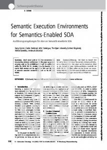
A sample metamodel and a simple model of finite automata are depicted in Figure 1. Metamodel
Automaton
Model :from :init
reachable
current
init State
color:{R,G,B}
states from
transitions
s1: State
Transition
to
:states
t3: Transition
:states a1: Automaton
:transitions :from :states
t1: Transition
:to
:to
:transitions
:transitions
s2: State
:from
s2: State :to
t2: Transition
Figure 1: A metamodel and model of finite automata
Example 1 According to the metamodel, a well–formed instance of a finite automaton is composed of states and transitions. A transition is leading between its from state and to state. The initial states of the automaton are marked with init, the active states
4
To Appear in the Journal of Periodica Politechnica
are marked with current, while the reachable states starting from the initial states are modeled by reachable edges. A sample automaton a1 consisting of three states (s1, s2, s3) and three transitions between them t1 (leading between s1 and s2), t2 (leading between s2 and s3), and t3 (leading between s2 and s3) is also depicted. We can notice that the initial state of a1 is s1.
2.2 Model Transformation Systems The dynamic operational semantics of a modeling language as well as transformations between modelin languages can be formalized by model transformation (transition) systems (introduced in [28]), which is a variant of graph transformation systems with a predefined set of control structures. A graph transformation rule is a 3-tuple �
������������������ ���� !�"�$# , where �%�"� is the left-hand side graph, !�"� is the right-hand side graph, while �&�'� denote the (optional) negative application conditions. � (e.g., a UML model of the user) The application of a rule to a model graph rewrites the user model by replacing the pattern defined by ����� with the pattern of the !�"� . This is performed by 1. finding a match of ����� in
�
(graph pattern matching),
2. checking the negative application conditions ��� � which prohibit the presence of certain nodes and edges (negative application conditions are denoted by graph objects with a cross),
�
that can be mapped to the 3. removing a part of the graph graph (yielding the context graph),
�����
4. gluing !�"� and the context graph to obtain the derived model
but not the
!�"�
�)( .
The entire model transformation process is defined by an initial graph manipulated by a set of model transformation rules (micro steps) executed in a specific mode in accordance with the semantics (macro steps) of a hierarchical control flow graph. � A model transformation (transition) system �+*,�-��.�/10324�� 5�7698!��# with respect to (one or more) type graph ��� is a triple, where .:/1032 defines the initial graph, is a set of model transformation rules (both compatible with ��� ), and 698!� is a set of � a control flow graphs defined as follows.
�
There are three types of nodes of the CFG: Try, Forall, and Loop. There are two types of edges: succeed and fail.
The control flow graph is evaluated by a virtual machine which traverses the graph according to the edges and applies the rules associated to each node. 1. When a Try node is reached, its associated rule is tried to be executed. If the rule was applied successfully then the next node is determined by the succeed edge, while in case the execution failed, the fail edge is followed. 5
To Appear in the Journal of Periodica Politechnica
2. At a Loop node, the associated rule is applied as long as possible (which may cause non-termination in the macro step). Only a succeed edge may lead from a Loop node. 3. When a Forall node is reached, the related rule is executed parallelly for all distinct (possible none) occurrences in the current host graph. Only a succeed edge may lead from a Loop node. Note that this CFG model follows the control flow concepts of the VIATRA tool. However, the use of “as long as possible” kind of control conditions (and additional negative application conditions) instead of forall nodes would almost directly yield the appropriate control conditions for many existing graph transformation tools. Example 2 A pair of rules describing how the reachability problem on finite automata can be formulated by graph rewriting rules is depicted in Figure 2. Rule initR states that all states of the automaton marked as initial are reachable (if the state has not been marked previously). Rule reachR expresses that if a reachable state * S1 ? do > MapAction; parallel execution ? 7: if ReadIsClassifiedObjectAction(State, s1) then 8: if A testLink(a1, reachable, s1) then 9: CreateLinkAction(a1, reachable, s1); 10: end if 11: end if 12: end for 13: end if
10
To Appear in the Journal of Periodica Politechnica
Starting point of pattern matching The first step, which is to find the starting point for pattern matching is, in fact, identical for all modes. Solution 3 The starting point of the pattern matching is identified by the instance retrieved by a ReadSelfAction executed on an instance of the model class (i.e., Automaton in our example) and stored in a variable (see Line 3 in Algorithm 1). As for the AS representation, a data flow is required to connect the output pin of ReadSelfAction with the input pin of AddVariableValueAction action. We must also specify that the previous value stored in the variable should be overwritten by setting the isReplaceAll variable to true. Note that matching instances of LHS graph nodes will be stored in AS variables (later on as well). Example 4 The AS representation of Line 3 in Algorithm 1 is depicted in Fig. 4. We expect to retrieve an Automaton instance stored in variable a1.
: OutputPin
: ReadSelfAction
: DataFlow source
result
destination a1:Variable
variable
: AddVariableValueAction
isReplaceAll=true
: InputPin value
a1 = ReadSelfAction()
Figure 4: Starting point of pattern matching
Type checking of objects Our next problem to be solved is to visit only type conforming objects when matching patterns. Solution 4 When an new object is obtained at any time during pattern matching (i.e., matched to a corresponding node in the graph transformation rule), we immediately test whether it has a conforming type (conformant to the type of the graph node). See Lines 4 and 7 in Algorithm 1 as examples. This testing is performed by a ConditionalAction with a test clause consisting of a single ReadIsClassifiedObjectAction. The test action ReadIsClassifiedObjectAction (checking whether an object is an instance of a certain class) has to return a boolean value on its output pin, which serves as the test output for the test clause in the meanwhile. If value retrieved by the test subaction of a clause is true then the body action of the clause can be executed (which consists of further actions of pattern matching in our case).
11
To Appear in the Journal of Periodica Politechnica
Example 5 The AS representation of Line 7 in Algorithm 1 is depicted in Fig. 5. We check whether the value stored in variable s1 is an instance of the class Automaton. Naturally, we first have to get this value from the variable by a ReadVariableAction connected to the input pin of ReadIsClassifiedObjectAction by a data flow.
then:Clause
: ReadIsClassifiedObjectAction
test clause
body if: ConditionalAction
testOutput ...:Action
result
: OutputPin
input
classifier
: InputPin
State: Class
destination
variable s1: Variable
: ReadVariableAction
result : OutputPin source
: DataFlow
if ReadIsClassifiedObjectAction(s1, State) then ...
Figure 5: Checking types of objects
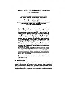
Navigating links The core operation of graph pattern matching in a UML environment is the navigation of links. Solution 5 When a certain object is matched, the neighbors of the object (connected by links corresponding to the edge types in the graph transformation rule) are obtained by navigating links (Line 5 in Algorithm 1). This navigation results in a single object or a collection of objects stored in a variable. A � navigation of a link in AS (by applying ReadLinkAction) means that
�
the exactly one end object (called the source object) of a link is already known (i.e., at most one LinkEndData may have an associated single value on its input pin), while the target end of the link should be unknown yet (naturally, an association can be navigated in both directions if allowed by the metamodel);
�
the link should correspond to a certain association (also defined by the LinkEndData); as a result of the navigation a single object or a set of objects is retrieved (depending on multiplicities of the association and the topology of interconnected objects), and stored in a variable.
Example 6 The AS representation of Line 5 in Algorithm 1 is depicted in Fig. 6. We read the value of variable a1 into the input pin of one LinkEndData corresponding to
12
To Appear in the Journal of Periodica Politechnica
cOm$ah`na�oOb f�p
eKf�Ot g3v
T3X�lQF J L�V�F J ]3L B�M L�HhDGF I7J L GVYz D�X BhPQJ L�R�SOL�TYU�VNF V
B�CEDGF H�D�F IKJ L
T3X�lQF J L�V�F J ]3L B3M L3HND�F IOJ L aOb Yv
t vYeOYb `
kB Z7l�lQ]�\NJ V�F J ]3LKSKL�T \Q]3L3L�X3\GF J ]YL v7_Yj
^ _Y^ ` ^ aObYc d$e3eYfOg3^ ah` ^ f�_
B3W7X�V3TYP�J L�R[Z7\QF J ]3L
v�_Yj7mEa3`na
B3U�V�F VO{3z ]G|
B3W7X3V�T�wrV3x J V3y3z XNZ4\GF J ]3L
eYf7Kt g3v
arq"c E s 7 a a7t ^ a�uYb v t ^ a�u3b v
^ _Y^ ` ^ aKbKc d$e3eYfOg3^ ah` ^ f7_Ki _hj \Q]YLNL�X�\GF J ]3L XYLQT v7_Yj7m$ah`na
B3PQJ L3R�S�L�TOU�V�F V
x X�l�D3z F B�CEDGF H�D�F IKJ L
BGZ4T3T�wrV3x J V3yhz XNw4V3z DQX3Z7\QF J ]YL } q"c3sEa7t ^ a7uhb v J lhW�X3H3z V3\�X�Zrz zG�F x D�X a �t ^ a7uYb v :~ DNz F J H�z J \�J F ::Y [�
k8� � � ��'�( ���8#?� � ���
C�D