Review
iMedPub Journals
Journal of Biomedical Sciences
http://www.imedpub.com/
ISSN 2254-609X
2016 Vol.5 No.4:29
DOI: 10.21767/2254-609X.100043
Effects of Decomposition Levels of Wavelets in Image Compression Algorithms Pandian R1*, Vigneswara T2 and Lalitha Kumari S1 1Sathyabama 2VIT
University, Chennai, India
University, Chennai, India
*Corresponding
author: Pandian
[email protected]
R,
Assistant
Professor,
Sathyabama
University,
Chennai,
India,
Tel:
919865768867;
E-mail:
Received Date: Jul 14, 2016; Accepted Date: Sep 29, 2016; Published Date: Oct 10, 2016 Copyright: © 2016 Pandian R, et al. This is an open-access article distributed under the terms of the Creative Commons Attribution License, which permits unrestricted use, distribution, and reproduction in any medium, provided the original author and source are credited. Citation: Pandian R, Vigneswara T, Kumari SL. Effects of Decomposition Levels of Wavelets in Image Compression Algorithms. J Biomedical Sci. 2016, 5:4.
Abstract Image compression finds extensive application in storage of image and image transfer. Image compression techniques require the application of suitable and effective transforms to achieve the task. In this work, Discrete Wavelet Transform based image compression algorithm is used for decomposing the image. The effectiveness of different wavelets with various decomposition levels are analyzed based on the values of Peak signal to Noise Ratio (PSNR), Compression ratio (CR), Means square error (MSE) and bits per pixel (BPP). The optimum compression algorithm is also found based on the results
Keywords:
Wavelet transforms; Daubechies; Embedded zero tree encoding
Symlets;
Coiflets;
Introduction Image storage and Image transmission leads to the large amount of memory requirements. Image compression techniques aid in the reduction of storage space and makes sharing of files easier. Image compression applications make use of various techniques and algorithms in compressing the images. The techniques can be generally classified as lossless and lossy compression [1]. If there is no compromise on high quality output without any loss in fidelity, lossless compression technique is used. Lossy compression technique is used in applications, where a compromise can be made in quality. In lossy compression, there is minor loss of quality, but the loss is too little to be visible. This technique is used in applications where a little compromise on quality of image is acceptable. For achieving the image compression, the image should be decomposed using suitable transforms [2]. Many transforms are used for accomplishing this such as adaptive lifting, wavelet transform and wavelet packets, etc., Rogerl Claypoole et al. [3] applied an Adaptive Lifting scheme for image reduction and obtained a MSE of 38.5 db for Doppler, Blocks etc. Rogerl Claypoole et al. [4] used Wavelet lifting methodology for image reduction for a cameraman image and it was evaluated with a
PSNR of 42 db. Cadder bank et al. [5] implemented Wavelet Transforms based image reduction for different images such as Bike, Café, Water and X-rays. In their work, entropy was used as a figure of merit and it was found as 5.90. Minh N Do et al. [6] used in Contourlet Transforms for both peppers and Barbara images. In their work also, entropy was used as a figure of merit and it was found as 30.47 db. Gemma Piella et al. [7] used wavelet lifting scheme for various images such as Rectangular, Crosses, Houses and Peppers. The performance is evaluated with the entropy values. Chenwei Deng [8] implemented DWTSeam carving methodology for a test image and bit – rate was used a figure of merit and it was found as 0.09. In this work, discrete wavelet transform is used for transforming the image and is primarily used for decomposition of images, whereas encoding is employed to achieve the entire compression process and Embedded Zero Tree wavelet is used to accomplish the image compression. In this work, a standard image is used for compression process. After the compression process, the quality of the image is estimated by both MSE and PSNR. The amount of compression is also found with Compression ratio. The paper is structured as follows. Chapter 2 enumerates the Transform technique and Chapter 3 discusses the encoding techniques. Results and discussion is explained in chapter 4 and this research work is concluded in Chapter 5.
Wavelet transforms In wavelet analysis, images are represented by a set of basic functions. A single prototype function called the mother wavelet is used for deriving the basis function, by translating and dilating the mother wavelet. The wavelet transform can be viewed as a decomposition of an image in the time scale plane. In this work, Daubechies, symlets and coifles are used. The basic and compact wavelet, which is proposed by Daubechies is an orthonormal wavelets, which is called as Daubechies wavelet. It is designed with extremely phase and highest number of vanishing moments for a given support width. Associated scaling filters are minimum-phase filter. Daubechies wavelets are generally used for solving fractal problems, signal discontinuities, etc. The symlets are nearly symmetrical wavelet, which are also proposed by
© Under License of Creative Commons Attribution 3.0 License | This article is available from: ${articleDOI}
1
Daubechies as modifications to the db family. Daubechies proposed modifications of her wavelets that increase their symmetry can be increased while retaining great simplicity. The symlets have properties similar to daubechies [9,10].
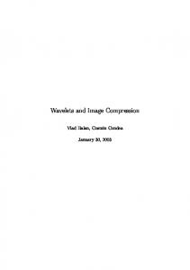
Encoding Embedded Zero trees of Wavelet transforms (EZW) is a lossy image compression algorithm. At low bit rates, i.e. high compression ratios, most of the coefficients produced by a sub band transform will be zero, or very close to zero. This occurs because "real world" images tend to contain mostly low frequency information (highly correlated). However where high frequency information does occur (such as edges in the image) this is particularly important in terms of human perception of the image quality, and thus must be represented accurately in any high quality coding scheme. By considering the transformed coefficients as a tree with the lowest frequency coefficients at the root node and with the children of each tree node being the spatially related coefficients in the next higher frequency sub band, there is a high probability that one or more sub trees will consist entirely of coefficients which are zero or nearly zero, such sub trees are called zero trees. Due to this, we use the terms node and coefficient interchangeably, and when we refer to the children of a coefficient, we mean the child coefficients of the node in the tree where that coefficient is located. We use children to refer to directly connected nodes lower in the tree and descendants to refer to all nodes which are below a particular node in the tree, even if not directly connected. Figure 1 shows flow chart of compression algorithms for various decomposition levels.
Journal of Biomedical Sciences
2016
ISSN 2254-609X
Vol.5 No.4:29
Zero tree Encoding is employed. The ability of the compression algorithms are evaluated in terms of MSE, PSNR, compression ratio and Bits per pixel. This is tabulated in Table1. The Quality of the reconstructed image is measured in terms of mean square error (MSE) and peak signal to noise ratio (PSNR) ratio. The ability of the compression can be analysed using the compression ratio and bits per pixel. The quality measures used for evaluating the image compression are peak signal to noise ratio, compression ratio, bits per pixel and mean square error. In this PSNR and Compression ratio are useful for image compression and data transmission �� =
Original image size in bits Compressed image size in bits
��� ���� ��� =
Compressed image size in bits Total number of pixels in the imag�
The number of bits of information stored per pixel of an image. The more bits there are, the more colours can be represented, but the more memory is required to store or display the image. The MSE is often called reconstruction error variance q2. The MSE between the original image f and the reconstructed image g at decoder is defined as ��� = �2� =
1 �
∑ (�[�, �] − �[�, �])2 �, �
Where the sum over j, k denotes the sum over all pixels in the image and N is the number of pixels in each image. From that the peak signal-to-noise ratio is defined as the ratio between signal variance and reconstruction error variance. The PSNR between two images having 8 bits per pixel in terms of decibels (dBs) is given by: ���� = 10���10
2552 ���
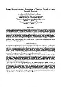
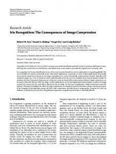
Generally when PSNR is 40 dB or greater, then the original and the reconstructed images are virtually indistinguishable by human eyes. The compression ratio of the image is given by No. of bits in original image/ No. of bits in compressed image. The original image, compressed image with Symlet2, level 1 decomposition and level 4 decomposition are shown in Figures 2-4 respectively.
Figure 1: Compression algorithm.
Results and Discussion In this work, Lena image is undergone the proposed algorithms. Discrete wavelet transform based decomposition was performed on the image. Symlet2, coiflet 2 and daubecheis2 are used for decomposing the image. Levels1, 2, 3 and 4 of decomposition are adopted. After the decomposition,
2
Figure 2: Original image.
This article is available from: ${articleDOI}
Journal of Biomedical Sciences
2016
ISSN 2254-609X
Vol.5 No.4:29
Decomposition level 4
Figure 3: Compressed image at decompostion level 1.
Transforms
DB 2
SYM 2
COIF 2
PSNR (dB)
44.82
44.82
44.8
BPP
10.47
10.47
10.35
CR(%)
43.63
43.63
43.14
MSE
2.15
2.143
2.15
If the decomposition level is increased, the PSNR value gets decreased, irrespective of the wavelet type. Both symlet2 and coiflet2 performed well at decomposition level 1, which is found, in terms of PSNR value. At decomposition level 2, The PSNR value is moderate, and also same for all the three types of wavelets. At higher decomposition levels, especially at 3 and 4, the three wavelets are not performed equally well. The PSNR values are almost same and very low, compared to levels 1 and 2. The bits per pixel values are also obtained and the variations in its values are also following the PSNR value, since, it is related to the PSNR. The mean square error is also increased if the level of decomposition is increased. It is wise to obtain a minimum value of error, which is also provided by symlet1 with the first level of decomposition.
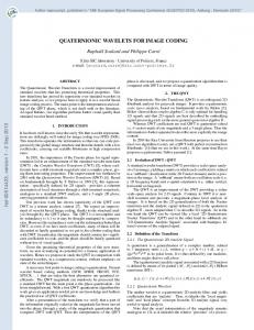
Conclusion Figure 4: Compressed image at decompostion level 4. Table1: Performance evaluation for decomposition levels. Decomposition level 1 Transforms
DB 2
SYM 2
COIF 2
PSNR (dB)
51.1
58.68
58.47
BPP
20.23
22.99
22.47
CR(%)
84.3
95.79
93.64
MSE
0.5045
0.088
0.09241
Decomposition Level 2 Transforms
DB 2
SYM 2
COIF 2
PSNR (dB)
50.55
50.55
50.41
BPP
16.9548
16.955
16.2937
CR(%)
70.65
70.65
67.89
MSE
0.573
0.573
0.5918
Decomposition level 3 Transforms
DB 2
SYM 2
COIF 2
PSNR (dB)
44.83
44.83
44.84
BPP
10.68
10.68
10.04
CR(%)
44.49
44.49
41.84
MSE
2.14
2.14
2.14
© Under License of Creative Commons Attribution 3.0 License
The main objective of this proposed work is to achieve a high compression ratio, which is also obtained with the same algorithm, based on symlet2. It is also achieved with a fourth level of decomposition. The bits per pixel of the various proposed algorithms are also decreased, if the level of decomposition is increased. The maximum compression ratio, lower PSNR values are obtained with the symlet2, level 1 of decomposition. Even though, the Embedded Zero Tree Encoding is employed for the above said transforms, the performances are varied, mainly due to the nature of the mother wavelets, used in this work. The Levels of decomposition also plays an important role in the compression algorithm, which is proven by the values of compression ratio and PSNR values. It is evident from the results, that the decomposition level of the image increases leads to the loss in information. This particular algorithm can also be applied for synthetic images, medical images also.
References 1.
Dhawan S (2011) A review of image compression and comparison of its algorithms. IJECT 3: 2.
2.
Said A, Pearlson AW (1996) An image multi resolution representation for lossless and lossy compression. IEEE Trans Image Process 5: 1303-1310.
3.
Claypoole R, Nowak RD (1998) Adaptive wavelet transforms via lifting. IEEE.
4.
Claypoole R (2003) Non- linear Wavelet transform for image coding via lifting. IEEE Trans Image Process 12: 1449-59.
5.
Calderbank R (1997) Loss less image compression using integer to integer wavelet transforms. IEEE.
3
6.
Do MN (2005) Counter let transform: An efficient directional multi resolutional image representation. IEEE Trans Image Process 14: 2091-106.
7.
Paella G (2005) Adaptive lifting schemes combining semi norms for lossless image compression. IEEE.
8.
Deng C, Lin W, Cai J (2012) Content-Based Image Compression for Arbitrary-Resolution Display Devices. IEEE Transactions on Multimedia 14: 1127-1139.
4
Journal of Biomedical Sciences
2016
ISSN 2254-609X
Vol.5 No.4:29
9.
Hong-wei MA, Bin W (2004) Application of Wavelet Transform to Signal de-noising in Ultrasonic Testing NDT 26: 68-71.
10. Wei Z (2006) Advanced Technology of Wavelet Analysis Based on
MATLAB, Published by XiDian University Press, Xi’anac Implants 24: 299-308.
This article is available from: ${articleDOI}