Department of Electronics and Electrical Communications. Faculty of Engineering ... Keywords: image interpolation, LMMSE, entropy, regularization theory, least squares. 1. ..... f â²(n1, n2) may be taken as the bilinear, Keys, cubic spline or cubic O-MOMS interpolated image. ... ized solutions for ill-posed problems [15, 16].
JOURNAL OF INFORMATION SCIENCE AND ENGINEERING 22, 1569-1583 (2006)
Short Paper_________________________________________________ Efficient Solutions for Image Interpolation Treated as an Inverse Problem S. E. EL-KHAMY1, M. M. HADHOUD2, M. I. DESSOUKY, B. M. SALLAM AND F. E. ABD EL-SAMIE 1
Department of Electrical Engineering Faculty of Engineering Alexandria University Alexandria 21544, Egypt 2 Department of Information Technology Faculty of Computers and Information Menoufia University Shebin Elkom 32511, Egypt Department of Electronics and Electrical Communications Faculty of Engineering Menoufia University Menouf 32952, Egypt This paper focuses on solving the image interpolation problem of noisy images as an inverse problem considering the mathematical model which relates the available noisy low resolution (LR) image to the required high resolution (HR) image. The paper presents four different solutions to this problem and compares their performance. First, an adaptive least squares interpolation algorithm is presented. Second, a Linear Minimum Mean Square Error (LMMSE) solution is suggested. An efficient implementation of this solution as a single sparse matrix inversion is presented. The sensitivity of this solution to the estimates of noise variance and the HR image autocorrelation is studied. Third, a mathematical model is derived for image interpolation based on the maximization of entropy of the required HR image a priori. This model is implemented as a single sparse matrix inversion. Finally, a sectioned implementation of regularized image interpolation is presented and implemented as a single matrix inversion as well. The effect of the choice of the regularization parameter on this solution is studied. The performance of all the above mentioned algorithms is compared from the PSNR, the computation cost and the edge preservation ability points of view. Keywords: image interpolation, LMMSE, entropy, regularization theory, least squares
1. INTRODUCTION Image interpolation is the process by which an HR image is obtained from an LR one. Image interpolation has a wide range of applications in numerous fields such as medical imaging, military applications, space imagery, image decompression and digital Received August 26, 2004; revised April 27, 2005; accepted August 11, 2005. Communicated by Kuo-Chin Fan.
1569
1570 S. E. EL-KHAMY, M. M. HADHOUD, M. I. DESSOUKY, B. M. SALLAM AND F. E. ABD EL-SAMIE
HDTV. The image interpolation problem has been intensively treated in the literature [1-5]. Conventional space invariant interpolation algorithms such as the bilinear, bicubic, cubic spline and cubic O-MOMS algorithms have been widely used [4-8]. On the other hand, spatially adaptive variants of the above mentioned algorithms have been developed as well [8]. Although these adaptive algorithms improve the quality of the interpolated image especially near edges, they still don’t consider the mathematical model by which the image capturing devices operate. In fact, most image capturing devices are composed of charge-coupled devices (CCDs). In CCD imaging, there is an interaction between the adjacent points in the object to form a pixel in the obtained image [9, 10]. Some image interpolation algorithms have been introduced considering this interaction process [9, 10]. The idea of LMMSE image interpolation was first introduced by Leung et al. [9]. It requires the segmentation of the image into small overlapping blocks and the interpolation of each block alone to avoid the large dimension matrix inversion process. The process of segmentation and interpolation of each segment requires a large number of matrix inversions. Another drawback is the edge effects in each interpolated segment. Another previously suggested interpolation algorithm is the regularized interpolation algorithm. This algorithm has been solved in a successive approximation manner to avoid the large dimension matrix inversion process [10]. In this paper, we first present an adaptive least squares interpolation algorithm. Then, we implement the LMMSE interpolation algorithm in an efficient manner, which doesn’t require segmentation leading to a single sparse matrix inversion. Also, another inverse algorithm is suggested for image interpolation based on maximization of entropy of the required HR image a priori. This algorithm is also implemented in a single sparse matrix inversion. Finally, the regularized interpolation algorithm is investigated and a non-iterative inverse solution for this algorithm is suggested. This solution requires a single matrix inversion of small dimensions in the whole image interpolation process if a global regularization parameter is used. The paper is organized as follows. Section 2 describes the LR image degradation model. Section 3 presents the idea of adaptive least squares interpolation. Section 4 investigates the LMMSE interpolator and suggests an efficient manner for the implementation of this interpolator. Section 5 introduces the mathematical model and the implementation of the maximum entropy image interpolator. Section 6 investigates the regularized image interpolator and suggests an efficient implementation of this interpolator using a single matrix inversion. The experimental results are introduced in section 7. Finally, the concluding remarks are introduced in section 8.
2. LR IMAGE DEGRADATION MODEL In the imaging process, when a scene is imaged by an HR imaging device, the captured HR image can be named f(n1, n2) where n1, n2 = 0, 1, 2, …, N − 1. If the same scene is captured by an LR imaging device, the resulting image can be named g(m1, m2) where m1, m2 = 0, 1, 2, …, M − 1. Here M = N/R and R is the ratio between the sampling rates of f(n1, n2) and g(m1, m2). The relationship between the LR image and the HR image, assuming no blurring, can be represented by the following mathematical model [9, 10]:
IMAGE INTERPOLATION AS AN INVERSE PROBLEM
1571
g = Df + v
(1)
where f, g and v are lexicographically ordered vectors of the unknown HR image, the measured LR image and additive noise values, respectively. The vector f is of size N2 × 1 and the vectors g and v are of size M2 × 1. The matrix D represents the filtering and down sampling processes. It is of size M2 × N2. Under the separability assumption, the matrix D can be written as follows [9, 10]: D = D1 ⊗ D1
(2)
where ⊗ represents the Kronecker product, and the M × N matrix D1 represents the one dimensional (1 − D) filtering and down sampling by a factor R. For N = 2M, D1 is given by [9, 10]:
1 1 0 D1 = 2 � 0
1 0 � 0
0 1 � 0
0 1 � 0
� � � �
0 0 � 1
0 0 . � 1
(3)
3. ADAPTIVE LEAST SQUARES IMAGE INTERPOLATION In this algorithm, the LR image is divided into small overlapping blocks of size M × M. We assume that the relation between the available LR and the estimated HR block is given by [11], fˆi , j = Wgi , j , where gi,j and fˆi , j are the M2 × 1 and N2 × 1 lexicographically ordered LR and the estimated HR blocks at position (i, j), respectively. W is the N2 × M2 weight matrix required to obtain the HR block. This matrix is required to be adaptive from block to block to accommodate for the local activity levels of each block. This leads to the least squares solution obtained by minimizing the MSE of estimation as follows [11]:
Ψ = ||f i , j − fˆi , j ||2 = ||f i , j − Wgi , j ||2 .
(4)
This minimization leads directly to the following solution for W as follows [11]: k
∂Ψ W k +1 = W k − η = W k + µ ( f i , j − fˆik, j )( gik, j )t ∂W
(5)
where η is a constant and is the µ convergence parameter. The usage of the above equation requires the samples of the original HR block to be known. An alternative approach is to consider the LR degradation model given for each block by the following relation [11], gi,j = Dfi,j.The matrix D is of size M2 × N2. Thus, we can minimize the following cost function, Ψ = ||D( f i , j − fˆi , j )||2 [11]. This means minimizing the MSE between the available LR block and a down sampled version of the estimated HR block. This leads to [11]:
Ψ = ||gi , j − Dfˆi , j ||2 = ||gi , j − DWgi , j ||2 .
(6)
1572 S. E. EL-KHAMY, M. M. HADHOUD, M. I. DESSOUKY, B. M. SALLAM AND F. E. ABD EL-SAMIE
Thus, the weight matrix can be adapted using the following equation [11]: k
∂Ψ k t k t ˆk W k +1 = W k − η = W + µ D ( gi , j − Df i , j )( gi , j ) . ∂W
(7)
The adaptation of Eq. (7) can be easily performed.
4. LINEAR MINIMUM MEAN SQUARE ERROR (LMMSE) IMAGE INTERPOLATION The LMMSE criterion requires the mean square error of estimation to be minimum over the entire ensemble of all possible estimates of the image. The optimization problem here is given by [12, 13]: min Ε [e t e ] = Ε [Tr (ee t )] fˆ
(8)
with, e = f − fˆ , where fˆ is the estimate of the HR image. Since the transformation D is linear, the estimate of f will be linear. That is an estimate of f can be derived by a linear operation on the degraded image such as, fˆ = Tg [12, 13], where T is derived subject to minimizing Eq. (8). This yields the following equation: min E[Tr (ee t )] = E[Tr{( f − Tg )( f − Tg ) t }] fˆ
= E[Tr{ ff t − T ( Dff t + vf t ) − ( ff t D t + fv t )T t + T ( Dff t D t + vf t D t + Dfv t + vv t )T t }].
(9)
Eq. (9) can be simplified using some assumptions. The noise is assumed to be independent on the required HR image and the autocorrelation matrices for the image and noise can be defined as, E[ff t] = Rf and E[vvt] = Rv. The matrix Rv is a diagonal matrix whose main diagonal elements are equal to the noise variance in the noisy LR image. This leads to the LMMSE estimator of the HR image as follows [12, 13]: fˆ = R f D t ( DR f D t + Rv ) −1 g.
(10)
In the implementation of the LMMSE model, three major problems are encountered [12]. The first one is the estimation of the autocorrelation matrix of the HR image. The second one is the noise variance estimation of the noisy LR image. The third one is the large dimension matrix inversion required in Eq. (10). We suggest efficient solutions to the above-mentioned problems. To solve the problem of estimating the autocorrelation of the HR image, the matrix Rf can be written in the form [12]: R0,0 R R f = 1,0 � R N −1,0
R0,1 R1,1 � �
� R0, N −1 � � � � � RN −1, N −1
(11)
IMAGE INTERPOLATION AS AN INVERSE PROBLEM
1573
where, Ri,j = E[fifjt], fi and fj are the ith and jth column partitions of the lexicographically ordered vector f. Often, pixels in an image possess no predictable correlation beyond a correlation distance d. If we assume that d = 0, then the matrix Rf can be approximated by a diagonal matrix in the form [12]: R0,0 0 Rf = � 0
0 � 0 � R1,1 � . � � 0 � 0 RN −1, N −1
(12)
If the samples of each column are assumed uncorrelated except for each pixel with itself, each matrix Rii can be approximated by a diagonal matrix for i = 0, 1, …, N − 1 as follows [12]:
� 0 0 R f (i, 0) 0 � � R ( i , 1) f . Rii = � � � 0 0 − � R i N 0 ( , 1) f
(13)
The main diagonal elements of the matrix Rii can be approximated from a polynomial based interpolated version of the available LR image. For an image f ′(n1, n2), the autocorrelation at the spatial location (n1, n2) can be estimated from the following relation [12, 14]: R f ( n1 , n2 ) ≅
1
w
w
∑ ∑ f ′(k , l ) f ′(n1 + k , n2 + l ) w2
(14)
k =1 l =1
where w is an arbitrary window length for the auto-correlation estimation. The image f ′(n1, n2) may be taken as the bilinear, Keys, cubic spline or cubic O-MOMS interpolated image. Thus, the matrix Rf can be approximated by a diagonal sparse matrix. The problem of noise variance estimation can be solved by estimating this value from the available LR image. The noise variance of the image is taken as the variance of a flat area in that image. The sensitivity of the LMMSE algorithm to this estimation is discussed in the simulation results. The third problem is the matrix inversion. This matrix inversion is of the order of M2 × M2 for an LR M × M image. This matrix is sparse in nature and can be inverted easily.
5. MAXIMUM ENTROPY IMAGE INTERPOLATION In this section, a mathematical model for image interpolation is derived based on the maximization of the entropy of the HR image a priori. If the samples of the required HR image are assumed to have unit energy, they can be treated as if they are probabilities, possibly of so many photons, which are present at the ith sample of the required HR im-
1574 S. E. EL-KHAMY, M. M. HADHOUD, M. I. DESSOUKY, B. M. SALLAM AND F. E. ABD EL-SAMIE
age [13]. The required HR image is assumed to be treated as light quanta associated with each pixel value. Thus, the entropy of the required HR image is defined as follows [13]:
He = −
N2
∑ fi log 2 ( fi )
(15)
i =1
where He is the entropy and fi is the sampled signal. This equation can be written in the vector form as follows: He = − f t log2(f).
(16)
For image interpolation, to maximize the entropy subject to the constraint that || g − Df ||2 = ||v||2 the following cost function must be minimized:
Ψ(f) = f t log2(f) − λ ||g − Df ||2 − ||v||2
(17)
where λ is a Lagrangian multiplier. Differentiating both sides of the above equation with respect to f, equating the result to zero and solving for the estimated HR image: f = exp[− 1 − λ ln (2)[2Dt(g − Df)]].
(18)
Making the necessary simplifications leads to:
fˆ ≅ ( D t D + η I ) −1 D t g
(19)
where η = − 1/(2λ ln (2)). We can use a direct inversion solution for Eq. (19). This solution is based on the direct inversion of the term (DtD + ηI). This matrix inversion can be performed easily depending of the special nature of this matrix that is a sparse diagonal matrix.
6. REGULARIZED IMAGE INTERPOLATION In section 2, we have concluded that the image interpolation problem for CCD captured images is an inverse problem. Regularization theory, which was basically introduced by Tikhonov and Miller, provides a formal basis for the development of regularized solutions for ill-posed problems [15, 16]. According to the regularization approach, the solution of Eq. (1) is obtained by the minimization of the cost function [15-17]:
Ψ ( fˆ ) = ||g − Dfˆ ||2 + λ||Qfˆ ||2
(20)
where Q is the 2-D regularization operator and λ is the regularization parameter. This minimization is accomplished by taking the derivative of the cost function, equating to zero and solving for that fˆ that provides the minimum of the cost function yields [15-17]: fˆ = ( D t D + λ Q t Q ) −1 D t g.
(21)
IMAGE INTERPOLATION AS AN INVERSE PROBLEM
1575
The rule of the regularization operator Q is to move the small eigenvalues of D away from zero while leaving the large eigenvalues unchanged. It also incorporates prior knowledge about the required degree of smoothness of f into the interpolation process. The regularization parameter λ controls the trade-off between fidelity to the data and the smoothness of the solution. A possible iterative solution to this problem can be carried out as follows [15-17]: fi+1 = fi + η0{Dtg − (DtD + λQtQ)fi}
(22)
where fi is the obtained HR image at iteration i and η0 is a convergence parameter. This method is a good solution that avoids the large computation cost involved in the matrix inversion process in Eq. (21). The drawback of this method is the large number of iterations required to get a good HR image. In this paper, we suggest another solution to the regularized image interpolation problem. This solution is implemented by the segmentation of the LR image into overlapping segments and the interpolation of each segment separately using Eq. (21) as an inversion process. It is clear that, if a global regularization parameter is used, a single matrix inversion process for a matrix of moderate dimensions is required because the term (DtD + λQtQ)-1 is independent on the image to be interpolated. Thus, the suggested solution is efficient from the point of view of computation cost. The interpolation formula can be written in the following form [15-17]: fˆi , j = ( D t D + λ Q t Q )−1 D t gi , j
(23)
where gi,j and fˆi , j , are the M2 × 1 and N2 × 1 lexicographically ordered LR and the estimated HR blocks at position (i, j), respectively.
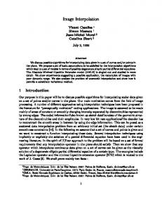
7. SIMULATION RESULTS In this section, a large number of experiments are carried out to test the performance of the suggested image interpolation algorithms and compare them to traditional image interpolation techniques. The images used in these experiments are first down sampled and then they are contaminated by additive white Gaussian noise to simulate the LR image degradation model given by Eq. (1). Next, the LR images are interpolated to their original size and the MSE is estimated between the obtained image and the original image. The value of the MSE is used to calculate the PSNR of the obtained image. We use two measures for performance evaluation of any image interpolation algorithm. These measures are the PSNR and the correlation coefficient for edge pixels between the original image and the interpolated image ce. In the first experiment, the LR 128 × 128 Woman image with SNR = 25dB is used to test both the quality and computation cost of the suggested algorithms as compared to traditional interpolation techniques. The results of the LMMSE image interpolation algorithm with autocorrelation matrices estimated from polynomial based image interpolation techniques are given in Figs. 1 to 4. It is clear that the LMMSE algorithm gives good interpolation result with autocorrelation matrix estimated from different polynomial based interpolation techniques.
1576 S. E. EL-KHAMY, M. M. HADHOUD, M. I. DESSOUKY, B. M. SALLAM AND F. E. ABD EL-SAMIE
(a) Cubic O-MOMS.
(b) LMMSE, PSNR (c) Keys. (d) LMMSE, PSNR = 22.13dB. = 22.07dB. Fig. 1. LMMSE interpolation results using bilinear and cubic spline interpolated images. (a) Bilinear, PSNR = 21.19dB, ce = 0.53. (b) LMMSE, PSNR = 22.12dB, ce = 0.7, CPU = 13s. (c) Cubic spline, PSNR = 21.02dB, ce = 0.5. (d) LMMSE, PSNR = 22.13dB, ce = 0.7, CPU = 15.3s.
(a) Bilinear. (b) LMMSE. (c) Cubic spline. (d) LMMSE. Fig. 2. Error images for LMMSE interpolation of woman image using bilinear and cubic spline interpolated images.
(a) Cubic O-MOMS.
(b) LMMSE, PSNR (c) Keys. (d) LMMSE, PSNR = 22.13dB. = 22.07dB. Fig. 3. LMMSE interpolation results using cubic O-MOMS and keys interpolated images. (a) Cubic O-MOMS, PSNR = 21.07dB. (b) LMMSE, PSNR = 22.13dB, ce = 0.7, CPU = 15.3s. (c) Keys, PSNR = 21.23dB, ce = 0.51. (d) LMMSE, PSNR = 22.07dB, ce = 0.7, CPU = 13.5s.
(a) Cubic O-MOMS.
(b) LMMSE, PSNR (c) Keys. (d) LMMSE, PSNR = 22.13dB. = 22.07dB. Fig. 4. Error images for LMMSE interpolation of woman image using cubic O-MOMS and keys interpolated images.
IMAGE INTERPOLATION AS AN INVERSE PROBLEM
1577
The LMMSE interpolation algorithm is insensitive to the method of autocorrelation estimation. This algorithm requires the inversion of a matrix of 16384 × 16384, which is sparse in nature. The maximum entropy image interpolation algorithm is tested on the same LR image with η = 0.001. This algorithm requires the inversion of a matrix of 16384 × 16384, which is sparse in nature. The result is given in Fig. 5. The maximum entropy solution requires less computation time as compared to the LMMSE algorithm and gives better PSNR values.
(a) Maximum entropy. PSNR = 22.31dB, ce = 0.71, CPU = 5sec.
(b) Error image.
Fig. 5. Maximum entropy interpolation of woman image.
(b) Error image. (a) Least squares. PSNR = 22.3dB, ce = 0.71, CPU = 449sec, Iav = 11.62. Fig. 6. Least squares interpolation of woman image.
The adaptive least squares image interpolation algorithm is also tested on the same LR image and the result is given in Fig. 6. In the implementation of this algorithm, the LR image is segmented into overlapping blocks of size 12 × 12 pixels each. Each block is interpolated separately to the size of 24 × 24 pixels and 8 pixels are removed from the four sides of each block to yield a small block of size 8 × 8 in order to avoid the edge effects. By the process of segmentation, the adaptive least squares technique requires the computation of a weight matrix of size 576 × 144 for each block, which is a moderate size. It is clear that the results obtained using this adaptive algorithm is approximately the same as that obtained using the maximum entropy algorithm but the computation time here is relatively large. Iav refers to the average number of iterations per block in the interpolation process. Both the iterative and inverse regularized image interpolation algorithms are tested on the same LR image with a global regularization parameter λ = 0.001 and the results are given Fig. 7. In the inverse regularized algorithm, the LR image is segmented using the same procedure followed in the least square algorithm. By the process of segmentation and the usage of a global regularization parameter, this technique requires a single matrix inversion of size 576 × 576, which is a moderate size. Results obtained using regularized image interpolation is good but the computation cost required is relatively larger than that of the LMMSE and maximum entropy algorithms. The LMMSE image interpolation algorithm is tested for different estimates of noise variance for the Woman image. The results are given in Fig. 8. It is clear from the figure that this algorithm is robust against small errors in estimating the noise variance. It is also better to use a lower estimate of the noise variance than to use a higher estimate. The effect of the parameter η on the maximum entropy image interpolation algorithm is studied
1578 S. E. EL-KHAMY, M. M. HADHOUD, M. I. DESSOUKY, B. M. SALLAM AND F. E. ABD EL-SAMIE
(a) Regularized iterative (b) Error image. (c) Regularized inverse. (100 iterations). PSNR = 21.91, ce = PSNR = 22, ce = 0.7, 0.63, CPU = 62s, λ CPU = 120s, λ = 0.001. = 0.001. Fig. 7. Regularized interpolation of woman image.
1000
800
800
600
MSE
1200
1000 MS E
1200
T
400
200
200
0 -6 10
-4
0 -6 10
-2
10
T
600
400
10
(a) Woman image SNR = 25dB.
(b) Error image.
-4
-2
10
10
(b) Woman image SNR = 15dB.
1000
1000
900
900
800
800
700
700
600
600 MSE
MS E
Fig. 8. Effect of noise variance estimation on LMMSE interpolation algorithm with autocorrelation estimated from cubic o-Moms interpolation. T refers to the point of the true noise variance estimate.
500
500
400
400
300
300
200
200 100
100 0 -5 10
Woman Test Pattern
Woman Test Pattern 10
-4
10
-3
η
10
-2
10
-1
10
Fig. 9. Effect of the choice of η on the maximum entropy image interpolation algorithm.
0
0 -5 10
10
-4
10
-3
λ
10
-2
10
-1
10
0
Fig. 10. Effect of the choice of λ on the inverse regularized image interpolation algorithm.
on both the Woman and the Test Pattern images. The results are given in Fig. 9. It is clear that this algorithm is insensitive to the choice of η in the range of 10-5 to 10-2 for both images. The effect of the choice of the global regularization parameter λ in the in-
IMAGE INTERPOLATION AS AN INVERSE PROBLEM
1579
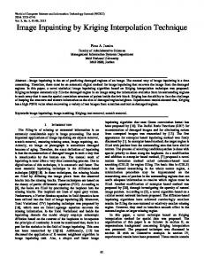
verse regularized image interpolation algorithm is studied on both the Test Pattern and Woman images and the results are given in Fig. 10. It is clear that the effect of λ on MSE is small for λ in the range of 10-5 to 1 for both images. The effect of λ is also studied for the iterative regularized interpolation algorithm and the results are given in Fig. 11. It is clear that the effect of λ on MSE is small for λ in the range of 10-5 to 10-2 for both images. 1000
440 Adaptive Keys LMMSE Max. Entropy Regularized Inverse Regularized Iterative Least Squares
900
430 800
420
700 600
MS E
MSE
410 500
400
400 300
390
200
380
100 0 -5 10
Woman Test Pattern 10
-4
10
-3
10
-2
10
-1
10
0
370 20
λ
25
30
35
40
SNR(dB)
Fig. 11. Effect of the choice of λ on the iterative regularized image interpolation algorithm
Fig. 12. A comparison between different interpolation algorithms for woman image.
Fig. 12 introduces comparisons between the different suggested interpolation algorithms for the Woman image. From the obtained results, it is clear that the maximum entropy algorithm gives the best interpolation results for the Woman image, which has so many details. On the other hand, the inverse regularized algorithm is the best for the Test Pattern image, which has so many edges with different orientations. Some other experiments have been carried out to compare the performance of the suggested inverse interpolation algorithms to the commercially available image processing software such as the ACDSee and Photopro. Results of these experiments are tabulated in Tables 1 to 3. These results reveal the superiority of the inverse interpolation algorithms to the commercially available methods whether they are edge adaptive or not.
8. CONCLUSION This paper suggests four efficient solutions for the image interpolation problem as an inverse problem. The first algorithm treats the image interpolation problem in an adaptive manner and gives good results but it is time consuming. The second algorithm tested in this paper is the LMMSE interpolation algorithm. In the paper also the concept of maximum entropy is extended to image interpolation and the implementation of this maximum entropy technique is suggested also in a single sparse matrix inversion. Finally, the regularized image interpolation algorithm is investigated and the implementation of this algorithm as a matrix inversion of moderate dimensions is suggested. The results
1580 S. E. EL-KHAMY, M. M. HADHOUD, M. I. DESSOUKY, B. M. SALLAM AND F. E. ABD EL-SAMIE
Table 1. Comparison between inverse interpolation and bilinear and cubic spline interpolation techniques for different noisy images (SNR = 20dB). Image
Cameraman (128 × 128) Lenna (64 × 64) Mandrill (128 × 128) Building (64 × 64) Plane (64 × 64)
Least Squares PSNR = 24.59 ce = 0.74 Iav = 19.56 CPU = 739s PSNR = 23.24 ce = 0.66 Iav = 5.74 CPU = 59s PSNR = 18.95 ce = 0.65 Iav = 23.04 CPU = 854s PSNR = 18.96 ce = 0.51 Iav = 13.53 CPU = 136s PSNR = 20.03 ce = 0.77 Iav = 33.09 CPU = 314s
Inverse Interpolation Techniques Maximum Regularized LMMSE Entropy Iterative
Regularized Inverse
PSNR = 24.25 ce = 0.77 CPU = 13s
PSNR = 24.58 ce = 0.75 CPU = 5s
PSNR = 24.3 ce = 0.74 CPU = 120s
PSNR = 25.58 ce = 0.83 CPU = 62s
PSNR = 23.29 ce = 0.73 CPU = 3.3s
PSNR = 23.33 ce = 0.65 CPU = 0.73s
PSNR = 23 ce = 0.66 CPU = 8.6s
PSNR = 24.32 ce = 0.78 CPU = 17s
PSNR = 18.82 ce = 0.65 CPU = 13s
PSNR = 18.96 ce = 0.64 CPU = 5s
PSNR = 18.8 ce = 0.63 CPU = 120s
PSNR = 19.12 ce = 0.66 CPU = 62s
PSNR = 18.64 ce = 0.63 CPU = 3.3s
PSNR = 18.75 ce = 0.51 CPU = 0.73s
PSNR = 18.64 ce = 0.5 CPU = 8.6s
PSNR = 18.19 ce = 0.47 CPU = 17s
PSNR = 25.19 ce = 0.82 CPU = 3.3s
PSNR = 25.07 ce = 0.77 CPU = 0.73s
PSNR = 24.47 ce = 0.78 CPU = 8.6s
PSNR = 26.18 ce = 0.87 CPU = 17s
Bilinear and Cubic Spline Interpolation Image Cameraman (128 × 128) Lenna (64 × 64) Mandrill (128 × 128) Building (64 × 64) Plane (64 × 64)
Bilinear
Adaptive Bilinear
Cubic Spline
Adaptive Cubic Spline
PSNR = 23.72 ce = 0.61 CPU = 1.1s PSNR = 22.6 ce = 0.57 CPU = 0.3s PSNR = 18.13 ce = 0.47 CPU = 1.1s PSNR = 17.21 ce = 0.24 CPU = 0.3s PSNR = 26.05 ce = 0.78 CPU = 0.3s
PSNR = 24.85 ce = 0.76, Iav = 3.14 CPU = 14.4s PSNR = 23.7 ce = 0.75, Iav = 3.65 CPU = 4.18s PSNR = 18.88 ce = 0.67, Iav = 4.38 CPU = 20s PSNR = 17.97 ce = 0.65, Iav = 3.81 CPU = 4.37s PSNR = 27.16 ce = 0.87, Iav = 3.11 CPU = 3.56s
PSNR = 23.63 ce = 0.6 CPU = 3.31s PSNR = 22.62 ce = 0.57 CPU = 0.82s PSNR = 17.99 ce = 0.44 CPU = 3.31s PSNR = 16.92 ce = 0.4 CPU = 0.82s PSNR = 24.38 ce = 0.71 CPU = 0.82s
PSNR = 24.62 ce = 0.73, Iav = 3.21 CPU = 31.86s PSNR = 23.82 ce = 0.72, Iav = 3.79 CPU = 9.4s PSNR = 18.77 ce = 0.61, Iav = 4.42 CPU = 43.8s PSNR = 17.54 ce = 0.57, Iav = 4 CPU = 9.93s PSNR = 25.42 ce = 0.8, Iav = 3.39 CPU = 8.4s
obtained from all the mentioned algorithms are compared from the PSNR, the computation cost and the edge preservation points of view. The regularized technique has proved to be the best technique for most cases except for images with large details where the maximum entropy image interpolation algorithm is the best. The treatment of the image interpolation problem as an inverse problem has proved to be better than treating it in a polynomial based method.
IMAGE INTERPOLATION AS AN INVERSE PROBLEM
1581
Table 2. Cubic O-MOMS and keys interpolation results of different noisy images with SNR = 20dB. Image
Cubic O-MOMS
Cameraman (128 × 128) Lenna (64 × 64) Mandrill (128 × 128) Building (64 × 64) Plane (64 × 64)
PSNR = 23.63 ce = 0.6 CPU = 3.31s PSNR = 22.66 ce = 0.57 CPU = 0.82s PSNR = 18.01 ce = 0.45 CPU = 3.31s PSNR = 16.94 ce = 0.4 CPU = 0.82s PSNR = 24.44 ce = 0.7 CPU = 0.82s
Cubic O-MOMS and Key Interpolation Iterative Cubic Keys O-MOMS PSNR = 24.12 ce = 0.74, Iav = 2.12 CPU = 23.21s PSNR = 23.48 ce = 0.73, Iav = 2.58 CPU = 7.06s PSNR = 18.6 ce = 0.6, Iav = 3.5 CPU = 38.32s PSNR = 17.35 ce = 0.56, Iav = 3.03 CPU = 8.29s PSNR = 24.77 ce = 0.82, Iav = 2.26 CPU = 6.19s
PSNR = 23.83 ce = 0.61 CPU = 1.5s PSNR = 22.71 ce = 0.56 CPU = 0.41s PSNR = 18.17 ce = 0.47 CPU = 1.5s PSNR = 17.18 ce = 0.22 CPU = 0.41s PSNR = 24.55 ce = 0.71 CPU = 0.41s
Iterative Keys (Adaptive & α) PSNR = 25 ce = 0.75, Iav = 2.88 CPU = 36.15s PSNR = 23.85 ce = 0.73, Iav = 3.51 CPU = 11.01s PSNR = 19.01 ce = 0.65, Iav = 4.24 CPU = 53.22s PSNR = 18.02 ce = 0.62, Iav = 3.68 CPU = 11.55s PSNR = 25.65 ce = 0.82, Iav = 3.02 CPU = 9.48s
Table 3. Interpolation results of different noisy images using the ACDSee and the PhotoPro. Commercial software (SNR = 20dB). Image Cameraman (128 × 128) Lenna (64 × 64) Mandrill (128 × 128) Building (64 × 64) Plane (64 × 64)
Lanczos
ACDSee Software Mitchell
Bell
PSNR = 21.15 ce = 0.44
PSNR = 21.56 ce = 0.47
PSNR = 21.76 ce = 0.49
PSNR = 20.55 ce = 0.41
PSNR = 20.91 ce = 0.44
PSNR = 21.02 ce = 0.48
PSNR = 15.66 ce = 0.44
PSNR = 16.14 ce = 0.29
PSNR = 16.46 ce = 0.33
PSNR = 15.09 ce = − 0.13
PSNR = 15.5 ce = − 0.11
PSNR = 15.84 ce = − 0.11
PSNR = 20.6 ce = 0.41
PSNR = 21.1 ce = 0.45
PSNR = 21.38 ce = 0.47
Image
Lanczos with Unsharp masking (edge Adaptive)
PhotoPro. Software Mitchell with Unsharp masking (edge Adaptive)
Bells with Unsharp masking (edge Adaptive)
Cameraman (128 × 128) Lenna (64 × 64) Mandrill (128 × 128) Building (64 × 64) Plane (64 × 64)
PSNR = 22.15 ce = 0.59 PSNR = 20.32 ce = 0.51 PSNR = 17.94 ce = 0.447 PSNR = 16.22 ce = − 0.2 PSNR = 19.99 ce = 0.68
PSNR = 22.54 ce = 0.62 PSNR = 20.59 ce = 0.55 PSNR = 18.18 ce = 0.46 PSNR = 16.45 ce = − 0.19 PSNR = 20.32 ce = 0.7
PSNR = 22.65 ce = 0.65 PSNR = 20.59 ce = 0.57 PSNR = 18.09 ce = 0.5 PSNR = 16.42 ce = − 0.13 PSNR = 20.44 ce = 0.73
1582 S. E. EL-KHAMY, M. M. HADHOUD, M. I. DESSOUKY, B. M. SALLAM AND F. E. ABD EL-SAMIE
REFERENCES 1. M. Unser, A. Aldroubi, and M. Eden “B-spline signal processing: Part I theory,” IEEE Transactions on Signal Processing, Vol. 41, 1993, pp. 821-833. 2. M. Unser, A. Aldroubi, and M. Eden “B-spline signal processing: Part II efficient design and applications,” IEEE Transactions on Signal Processing, Vol. 41, 1993, pp. 834-848. 3. M. Unser “Splines a perfect fit for signal and image processing,” IEEE Signal Processing Magazine, Vol. 16, 1999, pp. 22-38. 4. P. Thevenaz, T. Blu, and M. Unser, “Interpolation revisited,” IEEE Transactions on Medical Imaging, Vol. 19, 2000, pp. 739-758. 5. W. K. Carey, D. B. Chuang, and S. S. Hemami, “Regularity preserving image interpolation,” IEEE Transactions on Image Processing, Vol. 8, 1999, pp. 1293-1297. 6. J. K. Han and H. M. Kim, “Modified cubic convolution scaler with minimum loss of information,” Optical Engineering, Vol. 40, 2001, pp. 540-546. 7. H. S. Hou and H. C. Andrews, “Cubic spline for image interpolation and digital filtering,” IEEE Transactions on Acoustics, Speech and Signal Processing, Vol. ASSP-26, 1978, pp. 508-517. 8. G. Ramponi, “Warped distance for space variant linear image interpolation,” IEEE Transactions on Image Processing, Vol. 8, 1999, pp. 629- 639. 9. W. Y. V. Leung and P. J. Bones “Statistical interpolation of sampled images,” Optical Engineering, Vol. 40, 2001, pp. 547-553. 10. J. H. Shin, J. H. Jung, and J. K. Paik, “Regularized iterative image interpolation and its application to spatially scalable coding,” IEEE Transactions on Consumer Electronics, Vol. 44, 1998, pp. 1042-1047. 11. S. E. El-Khamy, M. M. Hadhoud, M. I. Dessouky, B. M. Salam, and F. E. A. ElSamie, “Adaptive least squares acquisition of high resolution images,” International Journal of Information Acquisition, Vol. 2, 2005, pp. 45-53. 12. S. E. El-Khamy, M. M. Hadhoud, M. I. Dessouky, B. M. Salam, and F. E. A. ElSamie, “Optimization of image interpolation as an inverse problem using the LMMSE algorithm,” in Proceedings of the IEEE Mediterranean Electrotechnical Conference, Vol. 1, 2004, pp. 247-250. 13. H. C. Anderws and B. R. Hunt, Digital Image Restoration, Prentice-Hall, Englewood Cliffs, New Jersey, 1977. 14. N. P. Galatsanos and R. T. Chin, “Digital restoration of multichannel images,” IEEE Transactions on Acoustics, Speech and Signal Processing, Vol. 37, 1989, pp. 415-421. 15. N. B. Karayiannis and A. N. Venetsanopoulos, “ Regularization theory in image restoration: the stabilizing functional approach,” IEEE Transactions on Acoustics, Speech and Signal Processing, Vol. 38, 1990, pp. 1155-1179. 16. M. G. Kang and A. K. Katsagelos, “Simultaneous iterative image restoration and evaluation of the regularization parameter,” IEEE Transactions on Signal Processing, Vol. 40, 1992, pp. 2329-2334 . 17. S. E. El-Khamy, M. M. Hadhoud, M. I. Dessouky, B. M. Salam and F. E. A. ElSamie, “Sectioned implementation of regularized image interpolation,” in Proceedings of the IEEE International Midwest Symposium on Circuits and Systems, Vol. 2, 2003, pp. 656-659. 18. S. E. El-Khamy, M. M. Hadhoud, M. I. Dessouky, B. M. Salam, and F. E. A. ElSamie, “A new approach for adaptive polynomial based image interpolation,” accepted for publication in the International Journal of Information Acquisition.
IMAGE INTERPOLATION AS AN INVERSE PROBLEM
1583
Said E. El-Khamy has received the B.Sc. (Hons) and M.Sc. degrees from Alexandria University, Alexandria, Egypt, in 1965 and 1967 respectively, and the Ph.D. degree from the University of Massachusetts, Amherst, U.S.A. in 1971. He joined the teaching staff of the Department of Electrical Engineering, Faculty of Engineering, Alexandria University, Alexandria, Egypt, since 1972 and was appointed as a full-time professor in 1982 and as the Chairman of the Electrical Engineering Department from September 2000 to September 2003. His current research areas of interest include communication systems, wave propagation and smart antenna arrays and modern signal and image processing techniques. He has published about two hundreds and fifty scientific papers in national and international conferences and journals. He earned many national and international research awards among which the IEEE, R.W.P. King best paper award of the Antennas and Propagation Society of IEEE, in 1980, the A. Schuman’s-Jordan’s award for Engineering Research in 1982, the Egypt’s State Scientific Engineering Sciences Excellence award for 2002 and the top appreciation award for 2004. He is secretary of Egypt’s national committee of URSI. Prof. El-Khamy is a Fellow of the IEEE since 1999. Mohiy M. Hadhoud received the B.Sc. and M.Sc. degrees in Electrical Engineering from Menoufia University in Egypt in 1976 and 1981 respectively. He received the Ph.D. degree from Southampoton University in 1987. He is currently a professor in the Department of Information Technology, Faculty of Computers and Information, Menoufia University. His areas of interests are signal processing, image processing, and digital communications.
Moaoad I. Dessouky received the B.Sc. and M.Sc. degrees in Electrical Engineering from Menoufia University in Egypt in 1976 and 1981 respectively. He received the Ph.D. degree from McMaster University in 1986. He is currently a professor in the Department of Electronics and Electrical Communications, Faculty of Electronic Engineering, Menoufia University. His areas of interests are signal processing, image processing, and digital communications.
Bassiouny M. Sallam received the B.Sc. degree in Electrical Engineering from Menoufia University and M.Sc. degree from Cairo University. He received the Ph.D. degree from Drexel University in U.S.A. He is currently working with the Department of Electronics and Electrical Communications, Faculty of Electronic Engineering, Menoufia University. His areas of interests are signal processing, image processing, and digital communications.
Fathi E. Abd El-Samie received the B.Sc., M.Sc. and Ph.D. degrees in Electrical Engineering from Menoufia University in Egypt in 1998, 2001 and 2005, respectively. He is currently working with the Department of Electronics and Electrical Communications, Faculty of Electronic Engineering, Menoufia University. His areas of interests are signal processing, image enhancement, restoration, super resolution and interpolation.