IEEE TRANSACTIONS ON POWER ELECTRONICS, VOL. 18, NO. 2, MARCH 2003
587
Fault Detection of Open-Switch Damage in Voltage-Fed PWM Motor Drive Systems Ricardo Lúcio de Araujo Ribeiro, Cursino Brandão Jacobina, Senior Member, IEEE, Edison Roberto Cabral da Silva, Fellow, IEEE, and Antonio Marcus Nogueira Lima, Member, IEEE
Abstract—This paper investigates the use of different techniques for fault detection in voltage-fed asynchronous machine drive systems. With the proposed techniques it is possible to detect and identify the power switch in which the fault has occurred. Such detection requires the measurement of some voltages and is based on the analytical model of the voltage source inverter. Simulation and experimental results are presented to demonstrate the correctness of the proposed techniques. The results obtained so far indicate that it is possible to embed some fault-tolerant properties for the voltage-fed asynchronous machine drive system. Index Terms—Fault detection, motor drive system, voltage source inverter.
I. INTRODUCTION
I
N most of the industrial applications the asynchronous machine is supplied by a voltage-source inverter. These ac drive systems are sensitive to different types of fault occurring at the input rectifier, or at the power inverter stage, or at the control sub-system. In general, when one of these faults occurs, the drive system has to be stopped for an unprogrammed maintenance schedule. The cost of these steps can be high and this suggests the development of fault tolerant control strategies for improving reliability. To introduce such strategies in motor drive systems as practical entities, hardware and software must perform the follow tasks: 1) fault detection; 2) fault identification; 3) remedial actions. A basic requirement to all fault-tolerant development is a comprehensive understanding of the regular system operation so that its behavior can be compared to that one at the onset faults. Several papers have been published proposing strategies to detect faults in motor drive systems. Initially, Spée and Wallace [1] proposed a fault tolerant system for a brushless dc motor. In that drive, the fault diagnosis is obtained from the comparison between the measured and predicted currents for fault conditions. Debebe et al. [2] suggested the use of a rule-based expert
system for fault diagnosis in a voltage-source inverter. To determine the faulty devices in the inverter, an interactive session between the user and the expert system is employed. Kastha and Bose [3] studied the behavior of an asynchronous machine fed by a voltage source PWM inverter during the fault occurrence. That study was made for key fault types normally verified on the industry applications. Blaabjerg et al. [4] introduced a technique to determine the output currents in a voltage-fed PWM inverter by using a single current sensor in the dc link. Such a solution was shown to be efficient for the global protection of the system but inadequate to identify faults. Ran et al. [5] presented a methodology to detect intermittent misfiring in a voltage-fed PWM\ inverter induction-motor drive. Their technique is based on the time-domain response of the stator currents. Recently, Peuget et al. [6] introduced two techniques to identify the fault mode of voltage-fed PWM inverter. The first one uses the analysis of the current-vector trajectory to identify fault modes. The second one determines the fault condition of the inverter from the instantaneous frequency of the current vector. More recently, Mendes and Marques [7] suggested to use the average motor currents Park’s vector monitoring for diagnosing voltage-fed inverter faults in ac drives. Note that techniques based on current pattern do not permit to identify whether the fault has occurred in the inverter or in the machine. In addition, most of the diagnosis techniques suggested above take at least one fundamental period between the fault occurrence and the fault detection. This paper proposes several techniques for fault diagnosis of an open-switch damage in voltage-source inverters. Such techniques require the measurement of voltages and are based on the analytical model of the voltage source inverter. Differently from the existing methods, the approach introduced here minimizes the time interval between the fault occurrence and the fault diagnosis. The proposed techniques can be embedded into the existing ac drive software as a subroutine without an excessive computational effort. II. FAULTS AND PROTECTION OF THE DRIVE SYSTEM
Manuscript received October 9, 2001; revised October 1, 2002. Recommended by Associate Editor J. Ojo. R. L. D. A. Ribeiro is with the Laboratório de Eletrônica, Industrial e Acionamento de Máquinas, Departamento de Engenharia Elétrica, Universidade Federal da Paraíba, Campina Grande, PB 58109-970, Brasil. He is also with the Departamento de Eletro-eletrônica, Centro Federal de Educação TecnológicaCEFET-MA, Brasil. C. B. Jacobina, E. R. C. da Silva, and A. M. N. Lima are with the Laboratório de Eletrônica Industrial e Acionamento de Máquinas, Departamento de Engenharia Elétrica, Universidade Federal da Paraíba Caixa, Campina Grande, PB 58109-970, Brasil (e-mail:
[email protected]). Digital Object Identifier 10.1109/TPEL.2003.809351
Fig. 1 shows the machine drive configuration on which the current investigation is focused. The different types of faults normally verified in the switching power stage are indicated as [3]. Depending on the nature of the fault, closing or represents the occurrence opening of switches of faults, which can be classified as [3] ; 1) dc link short-circuit to ground ; 2) dc link capacitor bank short-circuit ; 3) open-circuit damage of switch
0885-8993/03$17.00 © 2003 IEEE
588
IEEE TRANSACTIONS ON POWER ELECTRONICS, VOL. 18, NO. 2, MARCH 2003
Fig. 2.
Protection scheme of a commercial inverter.
Fig. 3.
Equivalent circuit of the inverter leg after the fault occurrence.
Fig. 1. Machine drive system configuration with the different types of faults.
4) short-circuit damage of switch ; ; 5) line to line short-circuit at machine terminal . 6) single line to ground fault at machine terminal The protection scheme of the machine drive system is usually designed to prevent the damage of the switching power converter. Fig. 2 shows the block diagram of a typical protection scheme for a commercial voltage-source inverter. Such a scheme includes the circuitry to prevent overvoltage and undervoltage of the dc link bus as well as the overcurrent of the inverter. Fuse relays protect the input side against overcurrent and thermal ones protect the electrical machine against overheating. A circuit breaker (CB) interrupts the input currents in the case of overload in the system. III. FAULT IDENTIFICATION In this work, only the open-circuit damage of a switch will be considered. Also, the effect of this type of fault in any other device is assumed to be symmetrical. Fault in one of the isolated base drive amplifiers of the inverter switches, can result in the fault type . A misfiring of the switch , for instance, reduces the pole inverter topology to the equivalent circuit presented in Fig. 3. In that circuit, the and voltage in phase “1” is determined by the phase current switching pattern of the switch . After the fault occurrence, can be expressed by Algorithm 1. It the pole voltage is expressed in terms of commands if (premise) … and/or (logical operation) … then (conclusion)… else if (alternative). is the dc-link voltage, and In that Algorithm, and correspond to the opened switch and closed switch, respectively.
Algorithm 1 Phase voltage ‘1’ after the fault occurrence then if else if
and
then
else if
and
then
The analysis above shows that the steady state after the fault occurrence introduces errors in the phase voltages in comparison to its normal operation. Based on this fact, it is possible to determine how these errors can be observed on several voltages measurements at key points of the drive systems. in Fig. 4 are the pole voltages Consider that are the phase voltages of the maof the inverter, is the neutral voltage of the machine. Kirchoff’s chine and, voltage law applied to that figure for balanced three phase load leads to
(1)
On the other hand, the effect of a fault in one of the inverter power switches can be represented by an error in the pole voltas representing the voltage ages of the inverter. Consider deviation in the neutral due to a fault in , for instance. Such a deviation affects the other voltages of the circuit as follows. • Phase voltages
(2) end if
RIBEIRO et al.: FAULT DETECTION OF OPEN-SWITCH DAMAGE
589
TABLE I FAULT IDENTIFICATION BASED ON THE INVERTER POLE VOLTAGE (TECHNIQUE T1)
Fig. 4. Possible location of the voltage sensors.
• Neutral voltage (3) TABLE II FAULT IDENTIFICATION BASED ON THE MACHINE VOLTAGE (TECHNIQUE T2)
• Line voltages (4) verified on the voltages indicated by the The deviation equations above can be detected by using voltage sensors placed in specifics points of the motor drive system as show in Fig. 4. allows to conceive fault The propagation of the effect of detection schemes that are based on the observation of such variables. IV. DETECTION TECHNIQUES The detection techniques employ a direct comparison of the measured voltages to their reference voltages obtained from the PWM reference signals. They can be classified as follows. 1) Technique T1—inverter pole voltage measurement. 2) Technique T2—machine phase voltage measurement. 3) Technique T3—system line voltage measurement. 4) Technique T4—machine neutral voltage measurement. ( , In these cases, the voltage error and ) is the variables used to both detect the fault and identify the faulty switch of a power inverter. Such error can be expressed as
TABLE III FAULT IDENTIFICATION BASED ON THE LINE VOLTAGE (TECHNIQUE T3)
(5) are the reference voltages, is the measured voltwhere is the voltage error verified at the fault condition, and ages, is the discretization error introduced in the PWM process. by the use of a It is possible to minimize the error calibration of measurements procedure. Such procedure employs a hysteresis detector that considers null the acceptable values for normal operation of the healthy drive. In this case, . the detection variable can be approximated by Equations (2)–(4) show that it is possible to estimate in what measure the voltage error will occur. Tables I–IV indicate how propagates to the voltage measurethe voltage error ments in the proposed techniques. From such Tables, one can implement a knowledge-based rule for fault diagnosis. Both and do not depend on the machine model techniques
because they are referred to the mid-point “ ” of the capacitor bank at the dc-link. Fig. 5 presents the block diagram for the fault diagnosis is accomsystem. The fault diagnosis for techniques plished in four steps as follows. 1) First step: measurement of voltages . 2) Second step: generation of the voltage error . 3) Third step: determination of the faulty condition and generation of the boolean errors . 4) Fourth step: identification of the faulty switch and gencomposed by the boolean eration of the digital word and , shown in Table V. signatures ,
590
IEEE TRANSACTIONS ON POWER ELECTRONICS, VOL. 18, NO. 2, MARCH 2003
TABLE IV FAULT IDENTIFICATION BASED ON THE NEUTRAL VOLTAGE (TECHNIQUE T4)
TABLE VI COMPARISON OF THE PROPOSED DETECTION TECHNIQUES
VI. SIMULATION RESULTS
Fig. 5.
Block diagram of the fault diagnosis system. TABLE V BOOLEAN SIGNATURES OF FAULTY SWITCHES
The identification of the faulty switch obtained from the technique T4 uses both the flag due to the Table IV and a flag which identifies the angular interval of the voltage error. V. COMPLEXITY OF IMPLEMENTATION AND EFFICIENCY The fault detection techniques investigated in this paper require the connection of voltage sensors at specific points of the drive system. The location and the number of these sensors defines the cost/benefit ratio for each one of proposed techniques. It has been considered at the present analysis that the drive operates as an open-loop controlled via a standard Volts Hertz scheme. Also, it is assumed that none of the fault detection techniques use any of the sensors already integrated in the drive. The location of extra sensor is indicated in Fig. 4. In that figure, the . Table VI voltage sensors are represented by summarizes the number of sensors, their location, the variables to be measured, and the type of the fault, for each of the detection techniques. It is important to observe that techniques and depend on the machine balance and need an accessible neutral terminal.
A simulation software has been implemented to test both the converter fault detection and identification techniques. An asynac drive system composed of a three-phase inverter sensors has been simulated. Modeling chronous machine the converter under fault has been accomplished with an ideal model of the switches, taking into account the conduction of the freewheeling diodes. The effective circuit topology is determined by examination of the phase current and the status of its base drive signal. The machine was modeled in the stationary axis using the stator and rotor flux linkages reference frame as state variables. The sensors are simulated considering that the voltages measurements are filtered by low-pass filter with cut-off frequency. To generate the required voltage 2 errors, the respective voltage references are filtered at the same condition. for switch is In the next results, the fault condition . Its detection is accomplished made to occur at . The time interval between the fault occurrence at and its detection is due to the persistence interval, that is . Such time interval is a delay introduced in the detection technique to prevent false diagnosis. This represents at most one fourth of the cycle, which is much less than what is obtained with other methods the authors are aware of. Fig. 6 presents the simulation results from application of the detection Technique . In the upper graph is shown the wavesuperimposed to the reference voltage form of pole voltage . In the lower one the voltage error is presented. Fig. 7 composed by the boolean flags , shows the digital word and that identify the faulty switch. The fault detection de. termined by these flags is observed in the instant The time delay between the fault occurrence and the fault detection is introduced to highlight the effect of the voltage error in the measurement. Fig. 8 presents the simulation results from the detection Technique . In the first graph is shown the waveform of the phase superimposed to the reference voltage . In the voltage is presented. The results obsecond graph, the voltage error tained for this case are similar to that related to Technique . The difference between them is due to the fact that Technique depends on the machine balance and accessibility of the neutral terminal. Fig. 9 presents simulations results from using the detection Technique . In that figure, the upper graph shows the line superimposed to its respective reference. The lower voltage
RIBEIRO et al.: FAULT DETECTION OF OPEN-SWITCH DAMAGE
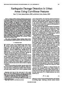
Fig. 6. Simulation results for the waveform of pole voltage v error " for Technique T1.
591
and voltage
Fig. 7. The digital word f related to the simulation results for Technique T1.
Fig. 8. Simulation results for the waveform of the phase voltage v voltage error " for Technique T2.
Fig. 9. Simulation results for the waveform of the line voltage v error " for Technique T3.
and
and voltage
one presents the voltage error . This technique does not depend on the machine balance. Fig. 10 presents simulation results from use of detection Technique . In that figure, the first graph shows the neutral . The second one presents the boolean flag voltage superimposed to the flag . The boolean flag determines refers the angular interval of the voltage error and the flag to its signal. This technique has the advantage of using only one voltage sensor when compared to other techniques. However, its efficiency depends on the balance of the machine which can result in incorrect detection. On the other hand, this technique needs the neutral terminal of machine to be accessible. VII. EXPERIMENTAL RESULTS The fault detection schemes have been tested experimentally with an ac drive set-up available at the laboratory. The drive system is composed of a static power converter, an asynchronous machine and a microcomputer (PC-Pentium-133 MHz). The generation of the command signals for the converter, the data
Fig. 10. Simulation results for the waveform of neutral voltage v boolean flags f and f for Technique T4.
and
592
IEEE TRANSACTIONS ON POWER ELECTRONICS, VOL. 18, NO. 2, MARCH 2003
Fig. 11. Experimental results for the waveform of the pole voltage v voltage error " for Technique T1.
Fig. 12. T1.
and the
The digital word f related of the experimental results for Technique
acquisition and the fault diagnosis system are implemented in a microcomputer-based platform equipped with appropriate plug-in boards and sensors. The faulty modes were artificially created by using by pass switches. Fig. 11 presents the experimental results from use of Technique . That figure shows the waveform of the pole voltage superimposed to the reference voltage for the fault on the switch . The fault has occurred at the instant , the diagnostic of the fault condition being realized . Notice that, because of experimental limitaat tions related to how the fault condition is simulated, the instant is different from that in Fig. 6. However, after the fault occurrence the waveform behavior are similar in both results. Fig. 12 composed by the boolean flags , presents the digital word and that identify the faulty switch. Fig. 13 presents the experimental results from using Technique . Its upper graph shows the waveform of the phase superimposed to the reference for the same fault voltage
Fig. 13. Experimental results for the waveform of the phase voltage v the voltage error " for Technique T2.
Fig. 14. Experimental results for the waveform of the line voltage v voltage error " for Technique T3.
and
and the
Fig. 15. Experimental results for the waveform of the neutral voltage v boolean flags f and f for Technique T4.
and
RIBEIRO et al.: FAULT DETECTION OF OPEN-SWITCH DAMAGE
condition as in previous experiment. The fault has occurred at and its detection is verified at instant the instant . The lower graph shows the voltage error . Fig. 14 shows the experimental results from application of the Technique . The first graph of that figure presents the wavesuperimposed to its correform of the system line voltage sponding reference. In the second one it is shown the voltage . The fault condition is simulated at the instant error and its detection is realized at the instant . Fig. 15 shows the experimental results from use of the voltage Technique . In the first graph of this figure presents the wave. In the second one is shown form of the neutral voltage superimposed to the flag . The fault has octhe flag and its detection is verified at curred at the instant . VIII. CONCLUSION Four detection techniques have been introduced for fault diagnosis in voltage-fed asynchronous machine drive systems. They are based on measurement of voltages at key points of the drive systems. The detection of the fault condition is achieved by comparing the voltages measurements to their respective references. The proposed techniques are based on an analytical model of the voltage-source inverter. The fault condition is detected within one fourth of the fundamental cycle. The differences among the proposed techniques are due to the fact that and depend on the machine model since they are refereed to the neutral terminal of the machine. Such dependence leads to an incorrect detection in the case of the machine unbalancing. In comparison to the existing detection methods, the proposed techniques present easier implementation and can be introduced in commercial motor drive system without any complexity. All of them need to incorporate extra voltage sensors in the system. However, this is justified when it is necessary to increase the reliability of those systems. Experimental and simulated results confirm the validity of the proposed techniques, which can be embedded into the existing ac drive software without an excessive computational effort. REFERENCES [1] R. Spée and A. K. Wallace, “Remedial strategies for brushless dc drive failures,” IEEE Trans. Ind. Applicat., vol. 26, pp. 259–266, Mar./Apr. 1990. [2] K. Debebe, V. Rajagopalan, and T. S. Sankar, “Expert systems for fault diagnosis of vsi fed ac drives,” in Proc. IAS’91 Conf., 1991, pp. 368–373. [3] D. Kastha and B. K. Bose, “Investigation of fault modes of voltage-fed inverter system for induction motor drive,” IEEE Trans. Ind. Applicat., vol. 30, pp. 1028–1038, July/Aug. 1994. [4] F. Blaabjerg, J. K. Pedersen, U. Jaeger, and P. Thoegersen, “Single current sensor technique in the dc link of three-phase pwm-vs inverters: a review and a novel solution,” IEEE Trans. Ind. Applicat., vol. 33, pp. 1241–1253, Sept./Oct. 1997. [5] L. Ran, K. S. Smith, and J. Penman, “Real-time detection of intermitent misfiring in a voltage-fed pwm inverter induction-motor drive,” IEEE Trans. Ind. Applicat., vol. 44, pp. 468–476, Aug. 1997. [6] R. Peuget, S. Courtine, and J. P. Rognon, “Fault detection and isolation on a pwm inverter by knowledge-based model,” IEEE Trans. Ind. Applicat., vol. 34, pp. 1318–1326, Nov./Dec. 1998. [7] A. M. S. Mendes and A. J. Marques, “Voltage source inverter fault diagnosis in variable speed ac drives, by the average current park’s vector approach,” in Proc. IEMDC’99 Conf., 1999, pp. 704–706.
593
Ricardo Lúcio de Araujo Ribeiro was born in Campina Grande, Paraíba, Brazil, in 1961. He received the B.S. and M.S. degrees in electrical engineering from the Federal University of Paraíba, Campina Grande, Brazil, in 1990 and 1992, respectively, where he is currently pursuing the Ph.D. degree. Since 1996, he has also been a faculty member of the Centro Federal de Educação Tecnológica do Maranhão-CEFET-MA, São Luis, Brazil. His research interests include power electronics and electrical drives.
Cursino Brandão Jacobina (S’78–M’78–SM’98) was born in Correntes, Pernambuco, Brazil, in 1955. He received the B.S. degree in electrical engineering from the Federal University of Paraíba, Campina Grande, Brazil, in 1978 and the Diplôme d’Etudes Approfondies and Ph.D. degrees from the Institut National Polytechnique de Toulouse, Toulouse, France, in 1980 and 1983, respectively. Since 1978, he has been with the Electrical Engineering Department, Federal University of Paraíba, where he is now Professor of electrical engineering. His research interests include electrical drives, power electronics, control systems, and system identification.
Edison Roberto Cabral da Silva (SM’95–F’03) was born in Pelotas, Brazil, on December 2, 1942. He received the B.C.E.E. degree from the Polytechnic School of Pernambuco, Recife, Brazil, in 1965, the M.S.E.E. degree from the University of Rio de Janeiro, Brazil, in 1968, and the D.Eng. degree from the University Paul Sabatier, Toulouse, France, in 1972. In 1967, he joined the staff of the Electrical Engineering Department, Federal University of Paraiba, Brazil, where he is a Professor of electrical engineering and Director of the Research Laboratory on Industrial Electronics and Machine Drives. In 1990, he was with COPPE, Federal University of Rio de Janeiro, and from 1990 to 1991, he was with WEMPEC, University of Wisconsin, Madison, as a Visiting Professor. His current research work is in the area of power electronics and motor drives. Dr. Da Silva was the General Chairman of the 1984 Joint Brazilian and LatinAmerican Conference on Automatic Control, sponsored by the Automatic Control Brazilian Society. Dr. da Silva is currently a Member-at-Large of the Executive Board of the IEEE Industrial Applications Society.
Antonio Marcus Nogueira Lima (S’77–M’89) was born in Recife, Pernambuco, Brazil, in 1958. He received the B.S. and M.S. degrees in electrical engineering from the Federal University of Paraíba, Campina Grande, Brazil, in 1982 and 1985, respectively, and the Ph.D. from the Institut National Polytechnique de Toulouse, Toulouse, France, in 1989. He was with the Escola Técnica Redentorista, Campina Grande, Paraíba, Brazil, from 1977 to 1982, and was a Project Engineer at Sul-América Philips, Recife, Pernambuco, Brazil, from 1982 to 1983. Since September 1983, he has been with the Electrical Engineering Department, Federal University of Paraíba, where he is now Professor of electrical engineering. His research interests are in the fields of electrical machines and drives, power electronics, electronic instrumentation, control systems, and system identification.