Hardware JIT compilation for off-the-shelf dynamically reconfigurable FPGAs Etienne Bergeron, Marc Feeley, Jean Pierre David {bergeret,feeley}@iro.umontreal.ca,
[email protected] DIRO, Universit´e de Montr´eal ´ GRM, Ecole Polytechnique de Montr´eal
Abstract. JIT compilation is a model of execution which translates at run time critical parts of the program to a low level representation. Typically a JIT compiler produces machine code from an intermediate bytecode representation. This paper considers a hardware JIT compiler targeting FPGAs, which are digital circuits configurable as needed to implement application specific circuits. Recent FPGAs in the Xilinx Virtex family are particularly attractive for hardware JIT because they are reconfigurable at run time, they contain both CPUs and reconfigurable logic, and their architecture strikes a balance of features. In this paper we discuss the design of a hardware architecture and compiler able to dynamically enhance the instruction set with hardware specialized instructions. A prototype system based on the Xilinx Virtex family supporting hardware JIT compilation is described and evaluated.
1
Introduction
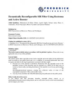
Software just-in-time (JIT) compilation is a well-known technique for improving the execution speed of virtual machine interpreters. The virtual machine identifies through run-time profiling which program parts are critical to its performance (so called hot spots) and compiles these parts into optimized machine code that is directly executed by the processor. Because the program’s behavior evolves throughout its execution, the virtual machine continually monitors the program to find the new hot spots to compile. The compiled code is often stored in a limited size cache which contains the most recently compiled parts of the program. Speed-ups are obtained when the monitoring and compilation effort are more than compensated by the execution time savings of the compiled hot spots. For this reason, time-consuming complex optimizations are typically not performed by JIT compilers. Hardware just-in-time compilation is an extension of this model to fieldprogrammable gate arrays (FPGAs). Figure 1 contrasts the software and hardware JIT models. FPGAs are highly parallel configurable digital circuits whose behavior can be tailored to a specific application in the field through the process of configuration. Normally this configuration is performed at power-up, but some FPGA families, namely the Xilinx Virtex II [19] and above, can reconfigure sections of the device at run time. This FPGA family also supports up
Central Processing Unit Sequential execution
Hardware JIT compilation
Configurable Logic Unit Parallel execution
System bus Software JIT compilation
Program Memory
Data Memory
DMA
Peripherals
Fig. 1. Software and hardware JIT models
to two classical processors inside the reconfigurable logic, which can be used to implement a virtual machine interpreter in software. A hardware JIT compiler, embedded in the virtual machine interpreter, will compile program hot spots into the low-level description (bitstream) of a digital circuit performing the same computation. The circuit’s layout and position in the reconfigurable logic as well as its interconnection with the processor running the virtual machine interpreter are determined dynamically. Circuit synthesis, placement and routing are rather time-consuming tasks. It is not uncommon for standard synthesis tools to take several minutes on a highperformance workstation to produce the bitstream for a simple computation. This high cost of compilation must be amortized on abnormally long running hot spots to achieve any speed-up. In order for hardware JIT compilation to be useful for executing more typical programs, it is necessary to decrease the compilation time by a few orders of magnitude. This is the obstacle we tackle in this work. Since the bitstream format of dynamically configurable FPGAs is not documented by the vendors, all the related work involving dynamical configuration are based on vendor-supplied proprietary compilation tools. Our recent work [1] has enabled us to extract enough information on the bitstream format to be able to generate partial bitstreams on-the-fly in a fraction of a second without any proprietary tool. We believe this is a key result on the road to general purpose reconfigurable computing. This paper describes the fast synthesis technique we have designed for a hardware JIT compiler. Sections 2 and 3 report on related work and give some background information on FPGAs. We describe a prototype compiler in Section 4. An evaluation of its performance is given in Section 5. We specifically focus our attention on the synthesis times.
2
Related Work
Reconfigurable architectures such as PipeRench [8,16] and WASMII [15] gave birth to the concept of virtual hardware. The idea is analogous to virtual memory. 2
Since the hardware resources on a chip are limited, it may be interesting to “store hardware” out of the chip and “swap hardware” when required. Such hardware manipulations require a dedicated area of the chip that is configurable. This means that it is possible to alter the logic or the connections via software. The store and swap mechanisms thus actually access the configurations bits, which are also called bitstream. Xilinx Virtex II and above FPGAs, which support dynamic reconfiguration, have also been used for virtual hardware implementation [4]. Two synthesis flows are proposed by Xilinx to handle the creation of dynamic modules using their tools [18]. Essentially, each possible global configuration of the FPGA must be pre-compiled using the standard synthesis process. Then, partial bitstreams are extracted from the complete bitstream for each module. The swapping from one configuration to another is achieved by sending a partial configuration to the FPGA. Standard tools were not originally developed for this type of compilation and their use imposes severe limitations on the design of virtual hardware. At present, it is still very difficult to develop, debug and guarantee the stability of dynamic applications. The RTR-JVM (Reconfigurable Run-Time Java Virtual Machine) [9] proposes a different approach where the concept of dynamic configuration is integrated in the language and its virtual machine. This architecture allows the dynamic loading of hardware modules produced from Java source code and translated to VHDL code. By profiling the hot spots, the system is able to identify good candidates for hardware implementation. The main limitation of this system is that modules are produced statically (by the standard synthesis flow) and preliminary executions are required. Warp processors [11] are another example of hardware virtualization. The authors propose to translate binary code to hardware [17] in order to make the production of dynamic modules transparent to the user. The advantage of this mode of execution is that it can be integrated to a conventional processor. That work is based on a custom FPGA [12] as well as custom tools, compilers and algorithms [13,14], which benefit from the regular structure of the custom FPGA. A drawback of custom FPGAs is that they lag commercial ones in terms of size, speed, and cost. The Warp project nevertheless demonstrated that JIT compilation is viable on modern FPGAs. We believe that on-the-fly generation of dynamic modules is appealing and needs more investigation. In this paper, we demonstrate that these techniques are applicable to commercial FPGAs despite their limitations in terms of architecture and synthesis tools.
3
Target Architecture
Our methodology assumes a dynamically reconfigurable FPGA with an embedded processor as illustrated in Figure 2. The application and the compiler are stored in an external memory and run on the embedded processor. Some peripherals can be mapped inside the FPGA configurable logic, allowing the 3
application to perform input/output. This zone is static, which means that it is configured at power-up and will not be modified later. The rest of the logic constitutes the reconfigurable zone, which will behave as a hardware cache for the dynamically generated specialized instructions. The compiler produces these instructions on-the-fly and configures the dynamic zone to make them available to the application through standard I/O instructions.
External memory
FPGA Embedded processor
Reconfigurable zone for dynamic instructions
Static peripherals Inputs/Outputs
Fig. 2. Diagram of a system supporting dynamic reconfiguration on a FPGA
In practice, we use Xilinx Virtex-II Pro devices, which are one of the few commercial devices currently supporting dynamic and partial reconfiguration. Moreover, these devices (and later series) are the most dense FPGAs available on the market. Figure 3 shows the layout of a small Virtex-II Pro device with one embedded PowerPC processor.
JTAG
IOB
PowerPC PPC405
CLB
BRAM Multiplier ICAP
Fig. 3. Virtex-II Pro Device Grid
4
A FPGA is mostly a grid of configurable blocks that can be interconnected in a configurable way. Input/Output Blocks (IOBs) are physically connected to the external pads. They are placed on the grid’s periphery. Configurable Logic Blocks (CLBs) are the heart of the processing power of the FPGA. Basically, each CLB contains user-defined lookup tables (LUT), registers and a programmable routing matrix to manage the connections to other CLBs. Virtex-II Pro FPGAs also contain hard-wired cores to increase the design density. The densest FPGA (2VP100) is equipped with 2 embedded PowerPC processors running at 400 MHz, 12 clock management devices, 444 18x18 bit multipliers, 444 block RAMs (18 kbits each) and almost 100000 CLBs spread all over the chip. Some special blocks are located at the chip’s periphery. The JTAG block is a serial interface provided for low level debugging. The Internal Configuration Access Port (ICAP) is used to configure the FPGA. In our architecture, it is connected statically to the PowerPC processor to enable dynamic configuration through standard I/O instructions. Given this architecture, the challenge we face is to quickly generate the configuration of the dynamic zone to enable efficient JIT hardware. More precisely, we have to configure the blocks and their interconnection. This is addressed in the next section.
4
Compiler Architecture
The next step is to build an execution environment running on the processors. Instead of writing a whole system from scratch, we decided to port the Gambit [6] Scheme to C compiler to the embedded PowerPC. This way, we inherit all Scheme features and a dynamic execution model (dynamic software module loading, dynamic code interpretation, etc). Gambit uses a fast interpretation technique [7] and gives access to the AST representation of the running program which the JIT compiler uses. Many languages can benefit from this kind of execution and we believe they can use a common back-end. High-level language synthesis, which consists in choosing how high-level concepts are mapped to hardware, is the most languagedependent phase but the running time of this phase is not a bottleneck. We have already addressed this issue in a previous work in the context of a static hardware compiler [2]. The hardware JIT compilation process follows the standard phases used to produce a FPGA bitstream: synthesis, technology mapping, place and route, bitstream generation and configuration. The synthesis phase translates a Scheme expression into a representation that explicitly indicates how high-level concepts are implemented (e.g. pipeline, state-machine,. . . ) to take advantage of hardware. The technology mapping phase attempts to map components generated by the synthesis to patterns and resources existing on the FPGA (multipliers, block RAMs, slices,. . . ). The place and route phase finds a location for each of the resources and connects them by assigning appropriate wires. Finally, the 5
bitstream generation produces a partial bitstream that will be downloaded into the configuration memory in the configuration phase. In a static compiler, these phases are optimized to produce a high-density, fast and low-power design. Problems faced by a JIT compiler are not the same and new techniques must be developed; the compilation time is one of the most important aspects. To minimize it, some trade-offs must be made. Thus, we prefer greedy algorithms over computation-intensive algorithms that could yield a more optimized design. In the following sections, we describe the algorithms and design choices made at each phase of the compilation. 4.1
Source Language and High-Level Synthesis
High-level synthesis of digital systems consists in transforming a behavioral (algorithmic) description of a design into a RTL (register transfer level) description of the design. This phase determines how the high-level concepts of the programming language are translated to low-level primitives. Decisions must be taken on how high-level concepts can be implemented in hardware. For example: should a function be implemented as a pipeline able to handle parallel calls, or as a state machine, much more compact but unable to handle parallelism? Other decisions must be taken such as which communication protocol to use between software and hardware. We chose to use Scheme [10] because it is a dynamic language quite easy to use and learn. Scheme provides a small set of primitive constructs with which most high-level features can be implemented. This simplifies the structure of the compiler. To elegantly provide dynamic compilation to hardware, our compiler is made available as a user-callable synthesize primitive. This primitive maps a function object, possibly a closure, onto the reconfigurable hardware. The sole parameter is a function and it returns a function which performs the same computation in hardware (i.e. semantically synthesize is the identity function). If the compilation fails, the primitive returns the argument unchanged. Thus, the complexity of hardware synthesis is hidden behind a single function. This approach meshes nicely with function closures which remember their environment of definition. For people versed in functional programming languages dynamic hardware synthesis with this extension is very natural. Hardware specialization is simply viewed as the partial evaluation of the function body given the binding of variables in the definition environment (i.e. the closure’s free variables). Figure 4 shows a use of the synthesize primitive. The call (adder 4) returns the closure which is an instance of the lambda-expression at line 3. This closure is a specialized version of an adder which always adds 4 to its argument. By passing this closure to the synthesize primitive, the system dynamically compiles the closure, configures the dynamic zone and returns another closure able to communicate with the dynamic instruction. When map calls that closure, 6
1 2 3 4
( define adder ( lambda ( x ) ( lambda ( y ) (+ x y ))))
5 6 7 8
( pretty - print ( map ( synthesize ( adder 4)) ’(1 2 3 4 5 6 7 8 9 10))
Fig. 4. Hardware synthesize/invocation of a specialized instruction
the argument is sent to the hardware’s input and the result is obtained from the hardware’s output. High-level synthesis is complex because many issues must be taken into account (e.g. memory access, global variables, continuations, threads. . . ). In our current prototype, we only support simple expressions containing arithmetic and logic operators. Much work remains to be done to determine how to perform high-level synthesis on general purpose languages. 4.2
Technology Mapping
Technology mapping consists in transforming technology-independent logical circuits into a technology-dependent mapping on a given technology. Typically, this phase is driven by a set of technology patterns defined in a library. Mapping is constrained by characteristics such as available physical gates, delays, available power and area. Compiler back-ends solve a similar problem when generating code. Two approaches are typically used: top-down and bottom-up. The top-down approach, often called Maximal Munch, consists in finding, in the library, a pattern that matches as much as possible from the root of the tree. Parts that were not matched are processed in the same way. Another approach is to use dynamic programming to find a way to cover the tree with a set of patterns. Our pattern library is designed to be a bridge between a high-level language and the low-level requirements imposed by the FPGA fabric. A typical operator has a height of 4 CLBs and uses one slice column (i.e. half of a CLB column). The use of a column of slices can be justified by the way fast carry chain logic works. We decided to use 4 CLBs (and 16-bit operators) because the configuration process works with 32-bit words and a CLB is 3 bytes wide. Thus, we obtain operators representable by a sequence of three 32-bit words. In addition, embedded multipliers are 18x18-bit and can implement 16-bit multiplication directly. Figure 5 shows typical operator patterns of our library. In our prototype, we decided to use a fast top-down approach. This phase takes less than a millisecond to perform mapping of a specialized instruction. It does not require much memory and is far from being the bottleneck of synthesis. 7
16 bit routing 16 bit operator LUT (2 LUTs / Slice) Slice (2 Slices / Column) Carry chain Switch matrix
CLB
2 operators / 4 CLBs
Fig. 5. Mapping of operators onto the FPGA fabric
4.3
Place and Route
Placement consists in finding a location for each component of the design. Locations are chosen to minimize the distance between dependent components and to maximize the probability of success of the routing phase. Sometimes, other criteria such as power consumption must also be taken into account. Routing consists in finding a path through static wires for each net. Placement and routing are the slowest phases of synthesis on FPGA. Running times of several minutes are common for these phases. Although phases are run separately, they are interdependent. A good placement facilitates routing, whereas a bad placement makes routing extremely complex. Because of the complexity of these phases, their algorithms are crucial to be optimized if we want to attain short compilation times. To understand current fast techniques, we briefly explain the VPR and the ROCR tools which are the fastest available algorithms for FPGA compilation. We then describe algorithms accelerating these phases. The VPR (Versatile Place and Route) [3] tool uses the simulated annealing algorithm for placement. The basic idea is to perform a random initial placement of all components. At each iteration, components are randomly swapped with a probability function of temperature and cost. The temperature gradually decreases until a threshold is reached. The VPR routing algorithm is an improvement over the Pathfinder negotiated algorithm [5]. Initially, it routes all nets with the shortest path regardless of the availability of resources. Dijkstra’s algorithm is used to find the shortest path. At each iteration, every route is sequentially re-routed by the lowest cost path. The cost of using a resource is a function of the overuse of that resource. At the end of the iteration, the costs of routing resources are adjusted accordingly to the amount of overuse in the previous iteration. By gradually increasing the cost of oversubscribed routing 8
resources, the algorithm forces nets to avoid them and to use alternative routes. Although VPR is quite fast, it is not fast enough for JIT place and route. ROCR (Riverside On-Chip Router) [13] is designed for hardware JIT compilation. It uses the basic cost model of VPR. To perform routing, it uses a global and detailed routing algorithm. The design of the fabric allows the algorithm to represent routing between CLBs as routing between switch matrices to which CLBs are connected. The global routing algorithm works like the VPR algorithm. Nets are initially routed with a greedy algorithm. Instead of un-routing all nets, only illegal nets are re-routed in an iteration. While using the same routing cost model as the VPR router, ROCR incorporates a small routing adjustment cost to all routing resources used by an illegal route. The routing adjustment cost discourages the greedy routing algorithm from selecting the same initial path in subsequent iterations. Once global routing is done, ROCR performs detailed routing which consists in assigning the channels (path in the switch matrix) used for each route. Two routes present a conflict when both routes pass through a given switch matrix and are assigned the same channel. This problem can be solved by a graph-coloring algorithm. The use of Brelaz’s vertex coloring algorithm allows a linear time approximation which is good enough for solving the routing problem. ROCR takes advantage of the regular and basic structure of the switch matrix of a custom made fabric. It is an order of magnitude faster than VPR and uses an order of magnitude less memory. To obtain a faster place and route algorithm, we explored several approaches. As JIT systems are typically used for high-level languages, we chose to restrict ourselves to fixed-width operators. We reduced the size of the problem by increasing the granularity of the operators, which operate on 16-bit integers. We also allowed algorithms to fail when problems are too complex, with a fallback invoking the more expensive algorithms.
Placement To simplify the placement algorithm, all operators are placed on a horizontal line whose height equals 4 CLB. Thus, the placement problem has only one dimension. We implemented a classical simulated annealing algorithm. It takes about 120 ms for a circuit of 30 operators and 300 nets. This algorithm gives quite good results and routing always succeeded in our tests. In our search for a faster algorithm, we attempted to implement a simpler algorithm which worked surprisingly well on our tests. We performed initial placement by flattening the expression tree in the topological order of the data dependencies. Then we performed a peep-hole optimization by trying every possible permutation of operators in a sliding window and kept the result with the lowest cost. This algorithm is greedy because it always keeps a better candidate when it finds one and never goes back to a worse solution. The algorithm loops until a stable state is reached. It usually needs about 3 iterations to find the best candidate, which takes less than 2 ms. The sliding window is illustrated in Figure 6. Notice that a CLB can have two overlapping operators (one for 9
each column of slices) and the routing matrix is shared by the two operators (Figure 5). 16−bit operator
16−bit bus
Sliding window
Fig. 6. Fast placement with peephole minimisation
This algorithm only requires a few kilobytes of memory. The results are not as good as the ones obtained by the simulated annealing algorithm but this does not affect the performance of the final circuit. Routing Routing is more complex than placement. Figure 7 shows routing resources used in our algorithm. FPGA routing resources consist of switch matrices connected by external wires. There are various kinds of external wires: simple, double and hex. Simple wires connect direct neighbors, double wires connect the first and second neighbors, and hex wires connect third and sixth neighbors. Longer paths are routed through multiple switch matrices using multiple external wires. Hex wires Double wires Direct wires
Primitive Pin
External wires
Routed Net
Switch matrix output wire
Switch matrix input wire
Configurable Switch Matrix
Primitive Pin
Fig. 7. Routing resources and a typical route
A typical route starts from a primitive pin, passes through a switch matrix, uses a wire to another switch matrix and ends at another primitive pin. All 10
programmable interconnect points (PIP) are in the switch matrix and nothing is configurable outside the CLB. The routing algorithm is split into two levels: external and internal routing. The algorithm applies a sequence of greedy external routers that call different internal routers to manage the routing inside the switch matrices. By carefully pairing external and internal routers and by applying greedy and efficient algorithms first, it is possible to minimize the routing time and obtain an efficient routing. Internal Router Paths inside a switch matrix and their corresponding Programmable Interconnects Points (PIP) are determined by the internal router. Internal routing is hard to achieve because the switch matrix is irregular, not fully connected and paths may be of various depths. This router finds the shortest path in the switch matrix from an input wire to an output wire. It takes into consideration all used resources and may fail if there is no path or if the routing is too complex. The first internal router is implemented using a lookup table. The shortest paths from all inputs to all outputs of a switch matrix are pre-computed. Therefore, if a resource in the shortest path is already used, the routing simply fails. The second internal router uses depth-first traversal. This algorithm is faster than Dijkstra’s algorithm because paths are usually very short. The depth-first search was implemented by a set of mutually recursive functions that represent the connectivity of the switch matrix. Thus, there is no data manipulation, only fast code execution. We ordered the recursive calls to maximize the likelihood of reaching an output point. External Router The external router drives the algorithm to determine where the next switch matrix is and which external wire is taken between switch matrices. As stated above, it uses an internal router as a helper to solve connections inside the switch matrix. External phases are sorted in such a way that most of the nets will be routed rapidly at the beginning while the remaining nets will be routed by a slower and more complex algorithm at the end. The direct phase routes nets that can be routed only by using direct wires. Thus, only direct neighbors can be routed by this phase. The next phase, general routing, tries to route nets that only use one double or hex wire. As the placement minimizes the distance between neighbors, after these two phases, almost all nets are routed except those passing through more than one switch matrix or larger than 6 CLBs. So, the next phase is greedy routing. The idea is to find recursively the best path through switch matrices by jumping as close as possible to the target. The last phase uses dynamic programming to find a valid path and is able to route any net unless resource conflicts make it impossible. Figure 8 shows examples of nets routed by each phase. As we see with the direct and general phases, only one external wire connecting two switch matrices is used. Greedy and dynamic routing use multiple external wires. We see the 11
Direct
General Greedy Dynamic
Fig. 8. Typical routes obtained with the 4 external routers
difference between greedy routing and dynamic programming routing: the greedy routing always jumps as close as possible. In the example, it jumps the longest possible path (6 CLBs) twice. The dynamic routing is able to find an alternative route but it is slower. It is used when conflicts occur with the greedy algorithm. Nets cache Each external router keeps a cache of routed nets to determine if another net can be routed the same way by applying a translation. There are many cache hits because we use fixed-width operators and all the bits of a given operator are often routed in the same way.
5
Results
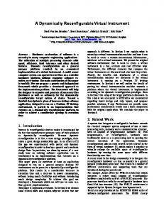
We synthesized the design on the ML310 demo board made by Xilinx. This system board has a Virtex-II Pro FPGA (2VP30) and 256 MB of external memory. The board has more components (e.g. PCI Bus, VGA, Ethernet connector. . . ) but they were not used in our basic design; we only used the external memory, the FPGA and the serial link. The program is running on the processor and communicates through a console attached to the serial link. Figure 9 shows a FPGA editor screenshot of a specialized intruction dynamically generated by our compiler. We observe the horizontal placement of 4 CLB high operators. To achieve high processing rates it is important to have a close coupling of the processor and the dynamic instructions to minimize the communication costs. It is also important for the dynamic instructions to exploit parallelism, for example with a pipelined circuit. Because these aspects are orthogonal to the placement and routing problems tackled in this paper we have used a less efficient interface adequate for testing the correctness of the synthesized circuits. In our prototype the input and output of the dynamic instructions are not interfaced to the processor bus. The parameters and results are communicated through the 12
Fig. 9. Specialized instruction dynamically produced by the JIT compiler
Internal Configuration Access Port (ICAP). The parameters become constant values and the result is read back from the state of the output register. Given the relatively slow speed of the ICAP interface, application speed-ups are not possible. To solve this issue we must work-around Xilinx design flow limitations; this work is still in progress. Given our goal to show that compilation time can be low enough to support hardware JIT compilation, we focus our attention on the synthesis phases. Therefore, instead of benchmarking applications, we evaluate the time needed to perform the placement and routing which are the bottlenecks of synthesis. slices nets
Place (ms) Route (ms) S.A. fast-place dynamic no-table no-cache fast-route 48 80 3 0 3 2 4 2 64 112 8 0 5 3 5 3 80 144 7 0 4 3 3 3 144 272 47 2 12 5 4 4 224 432 166 6 227 143 19 14 440 864 763 46 1161 385 101 50 Table 1. Place and route times for specialized intructions
Table 1 shows place and route times for expressions of various sizes (from 6 to 55 operators). For the placement, we compare the simulated annealing implementation with our fast implementation. We observe that our fast implementation is about 20 times faster. It is important to note that our simulated annealing implementation is already faster than current hardware synthesis tools because it also performs one-dimensional placement of fixed-width operators. The last set of columns shows the routing time of expressions. By disabling the cache, we observe that the routing speed is halved. We also observe the speedup obtained by using pre-computed tables for switch matrices by comparing the fast-route and the no-table columns. The dynamic column shows the worst case of our algorithm when all nets are routed with the dynamic programming router. Typical routing tools use the Pathfinder and Dijkstra’s algorithm. At each iteration, they re-route wires. Our algorithm is not iterative and routes each wire only once. Dijkstra’s algorithm’s speed should be similar to the dynamic 13
router speed. As VPR uses an iterative algorithm with Dijkstra’s algorithm, its speed should be of the same order. Our algorithm does not iterate and only applies a sequence of greedy routers. Speed-ups come from the fact that most nets are routed by a faster router. Table 2 shows how many nets are routed by each internal and external router. Almost all nets are routed by the direct and general routers and a few nets really need a depth-first traversal to find a path. This explains why our algorithm is efficient. nets 80 112 144 272 432 864
6
pre-computed tables depth-first traversal direct general greedy dynamic direct general greedy dynamic 56 16 0 0 8 0 0 0 68 32 0 0 12 0 0 0 56 80 0 0 8 0 0 0 140 120 0 0 12 0 0 0 136 252 35 0 8 0 0 0 224 532 88 0 0 0 0 0 Table 2. Number of nets routed by each internal phase
Conclusion
We have described a hardware JIT compiler for dynamically reconfigurable FPGAs. At run time, the JIT compiles function closures to a hardware circuit which is downloaded to the reconfigurable zone of the FPGA. The JIT performs all the normal phases of hardware synthesis including placement and routing. To achieve good compilation speed we use a set of routing algorithms of increasing complexity which are tried in a cascade. Most if not all of the work is usually performed by the cheaper algorithms. The prototype we have built for the Xilinx Virtex II Pro FPGA demonstrates that modest sized functions can be compiled to hardware in a few milliseconds. Our experiments show that naive algorithms and lookup tables significantly speed-up placement and routing. Various heuristics and naive fast algorithms may be adapted to FPGAs depending on their specific characteristics. We do not claim to have the best set of algorithms. Our claim is that compilation times compatible with JIT compilation are attainable on current reconfigurable FPGAs. We hope that our work will spur further research on hardware JIT compilation for general-purpose languages.
References 1. Etienne Bergeron, Marc Feeley, and Jean Pierre David. Toward On-Chip JIT Synthesis on Xilinx Virtex-II Pro FPGAs. In 50th International Midwest Symposium on Circuits and Systems/5th International Northeast Workshop on Circuits (MWCAS/NEWCAS), Montreal, Canada, August 2007.
14
2. Etienne Bergeron, Xavier Saint-Mleux, Marc Feeley, and Jean Pierre David. Highlevel synthesis for data-driven applications. In IEEE International Workshop on Rapid System Prototyping, pages 54–60, 2005. 3. Vaughn Betz and Jonathan Rose. VPR: A new packing, placement and routing tool for FPGA research. In Wayne Luk, Peter Y. K. Cheung, and Manfred Glesner, editors, Field-Programmable Logic and Applications, pages 213–222. Springer-Verlag, Berlin, 1997. 4. G. Brebner. The swappable logic unit: a paradigm for virtual hardware. In FCCM ’97: Proceedings of the 5th IEEE Symposium on FPGA-Based Custom Computing Machines, Washington, DC, USA, 1997. 5. Carl Ebeling, Larry McMurchie, Scott A. Hauck, and Steven Burns. Placement and routing tools for the Triptych FPGA. IEEE Trans. Very Large Scale Integr. Syst., 3(4):473–482, 1995. 6. Marc Feeley. Gambit-C. http://www.iro.umontreal.ca/˜gambit. 7. Marc Feeley and Guy Lapalme. Using closures for code generation. Computer Languages, 12(1):47–66, 1987. 8. Seth Copen Goldstein, Herman Schmit, Mihai Budiu, Srihari Cadambi, Matt Moe, and R. Reed Taylor. PipeRench: A reconfigurable architecture and compiler. Computer, 33(4):70–77, 2000. 9. Brian Greskamp and Ron Sass. A Virtual Machine for Merit-Based Runtime Reconfiguration. In IEEE Symposium on Field-Programmable Custom Computing Machines, April 2005. 10. Richard Kelsey, William Clinger, and Jonathan Rees (Editors). Revised5 Report on the Algorithmic Language Scheme. ACM SIGPLAN Notices, 33(9):26–76, 1998. 11. R. Lysecky, G. Stitt, and F. Vahid. Warp processors. ACM Transactions on Design Automation of Electronic Systems, pages 659–681, July 2006. 12. R. Lysecky and F. Vahid. A configurable logic architecture for dynamic hardware/software partitioning. In Design Automation and Test in Europe Conference, 2004. 13. R. Lysecky, F. Vahid, and S. X.-D. Tan. Dynamic FPGA routing for just-in-time FPGA compilation. Design Automation Conference, pages 954–959, 2004. 14. R. Lysecky, F. Vahid, and S. X.-D. Tan. A study of the scalability of on-chip routing for just-in-time FPGA compilation. IEEE Symposium on Field-Programmable Custom Computing Machines, pages 57–62, 2005. 15. Xiao ping Ling and Hideharu Amano. Performance evaluation of WASMII: a data driven computer on a virtual hardware. In PARLE ’93: Proceedings of the 5th International Conference on Parallel Architectures and Languages Europe, pages 610–621, London, UK, 1993. Springer-Verlag. 16. H. Schmit, D. Whelihan, A. Tsai, M. Moe, B. Levine, and R. Reed Taylor. PipeRench: A virtualized programmable datapath. Proceedings of the IEEE 2002 Custom Integrated Circuits Conference, pages 63–66, 2002. 17. G. Stitt and F. Vahid. Binary Synthesis. ACM Transactions on Design Automation of Electronic Systems, 12(3):34, 2007. 18. Xilinx. XAPP290: Two Flows for Partial Reconfigurable Core Based on Small Bit Manipulations. Technical report, Xilinx, September 2002. 19. Xilinx. Virtex-II Pro and Virtex-II Pro X Platform FPGAs: Complete Data Sheet. Technical report, Xilinx, June 2005.
15