partitioned on a single-chip microprocessor/FPGA device. Keywords. Hardware/software ..... [3] P. Athanas, H. Silverman: Processor Reconfiguration. Through ...
Hardware/Software Partitioning of Software Binaries Greg Stitt and Frank Vahid* Department of Computer Science and Engineering University of California, Riverside {gstitt | vahid}@cs.ucr.edu, http://www.cs.ucr.edu/~vahid * Also with the Center for Embedded Computer Systems at UC Irvine
Abstract Partitioning an embedded system application among a microprocessor and custom hardware has been shown to improve the performance, power or energy of numerous examples. The advent of single-chip microprocessor/FPGA platforms makes such partitioning even more attractive. Previous partitioning approaches have partitioned sequential program source code, such as C or C++. We introduce a new approach that partitions at the software binary level. Although source code partitioning is preferable from a purely technical viewpoint, binary-level partitioning provides several very practical benefits for commercial acceptance. We demonstrate that binary-level partitioning yields competitive speedup results compared to source-level partitioning, achieving an average speedup of 1.4 compared to 1.5 for eight benchmarks partitioned on a single-chip microprocessor/FPGA device.
Keywords Hardware/software partitioning, synthesis, binary translation, decompilation, low power, assembly language, FPGA, codesign, synthesis.
1. Introduction Much previous work has shown the advantages of hardware/software partitioning in embedded system design. Hardware/software partitioning divides an application into software running on a microprocessor and some number of coprocessors implemented in custom hardware. The custom hardware may be implemented as a new application-specific integrated circuit, but could instead be mapped to configurable logic, such as a field-programmable gate array (FPGA). Advantages of such partitioning include order-of-magnitude improvements in performance (e.g., [18][19]), as well as reductions in power or energy [21][22][37]. The advent of single chip microprocessor/configurable-logic platforms makes such partitioning even more attractive [2][4][19][31][33][38]. Embedded systems developers can thus gain the same time-to-market, cost and single-chip board-size advantages previously only possible with software-only implementations, while now also gaining the performance and energy advantages possible through hardware/software partitioning. Nearly all hardware/software partitioning approaches partition at the source code level. In particular, they partition during or even before compilation of the source program. From a purely technical point of view, the source code level is probably the best place to perform partitioning. However,
successful technologies are not always based on the best technical solution alone. Other considerations can play a critical role. In this paper, we highlight previous work in traditional hardware/software partitioning, and we describe tool flow problems that cause resistance to the adoption of such partitioning in commercial environments. We propose software binary partitioning as a solution to those problems. We show that binary partitioning can achieve results competitive with source code partitioning, by drawing on previous work in decompilation. We point to future work needed to make binary partitioning even more competitive.
2. Previous Work Hardware/software partitioning techniques have been proposed over the last decade, and several automated commercial products have recently appeared. Early work by Gupta [30] focused on taking a behavioral hardware specification and moving non-critical regions to software, to reduce hardware cost. The behavioral specification was read into a synthesis internal format of a hierarchical control/dataflow graph, and then partitioned using automated heuristics coupled with size and performance estimators. Henkel [14] proposed instead to start with a software program, moving pieces to hardware to improve speed. They read the software into a source statement-level internal format that was then partitioned. TOSCA [6] read in a software program that was then converted to a generic assembly-level format and partitioned. The assembly-level format enabled good estimates of software performance and size for a variety of processors. SpecSyn [15] partitioned at a coarser level, reading a behavioral specification (from a software source or a hardware description language) into a procedure-level internal format, and partitioning processes and procedures among hardware and software. For software estimation, they also compiled procedures into a generic assembly-level. Kalavade [24] also partitioned behavior at a coarse level of tasks. Eles [13] and Henkel [20] investigated partitioning at various levels of granularity, ranging from statements to blocks to procedures. OCAPI [34] focuses on supporting partitioning of a software program at various stages of design refinement, from the early system level, to just before software and hardware code generation. Dozens of other efforts in the hardware/software codesign community have focused on similar partitioning at various levels of granularity. Partitioning has also been addressed by the reconfigurable computing community, seeking to speedup software by using FPGA coprocessors. PRISM [3] was an early effort targeting a
0-7803-7607-2/02/$17.00 ©2002 IEEE
164
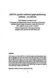
Figure 1: Hardware/software partitioning approaches: (a) traditional source-based approach (b) proposed binary-based approach and (c) typical structure of a hardware/software partitioner.
Sw source Compilation
Sw source Compiler Front-End
Assembly & object files
Assembler & Linker Hw/sw partitioning
Hw/sw partitioning Compiler Back-End Assembly & object files
Internal format creation
Binaries Hw source
Hw/sw partitioning
Assembler & Linker
Synthesis
Hw source
Binaries
Netlists
Synthesis Binaries
(a)
Profiling Sw generation
Internal format Sw estimation Hw estimation
Exploration Hw generation
Netlists (c)
(b)
Motorola 68010 processor and four Xilinx 3090 FPGAs. The Berkeley BRASS project [9] extended a C compiler to partition among the Garp [19] architecture, which combines a MIPS with reconfigurable logic. The NAPA C compiler [18] allows the user to provide pragma directives to specify where computation is to occur or where data is to reside on a micprocessor/FPGA platform. The Nimble compiler [16][26] was to compile C code to an architecture consisting of a general-purpose processor with a reconfigurable-datapath coprocessor. Proceler’s product [29] compiles C code to a processor and an FPGA coprocessor. Both used profiling information to detect and move critical software regions to the FPGA. DEFACTO [8] partitions an application based on the intermediate format of the SUIF compiler [1]. The Cameron project [7][10] uses a variation of C and maps to a platform consisting of a PC and a multi-million gate FPGA board. They use a compiler to extract massive parallelism of the critical loops and obtain speedups of several hundred times. Most partitioning work focuses on the performance benefits of such partitioning. Recent research has emphasized energy benefits also [21][22][32][37], achieved by using the performance speedup to put the system in a low power idle state for a longer period, or to scale down the system operating voltage while still meeting timing constraints.
3. Source versus Assembly Level Partitioning All work mentioned above partitions either before software compilation (e.g., [15][24]), or more commonly, as part of
compilation. Partitioning during compilation is illustrated in Figure 1(a). A compiler front-end reads the source code into an intermediate format, such as SUIF [1]. This intermediate format is annotated with profiling data. The critical regions are detected, and those parts are examined for potential implementation in hardware. The regions destined for software are then fed through a compiler back-end to generate assembly code for a processor, while the parts intended for hardware are fed to a synthesis tool (typically by first generating hardware description language code) for hardware implementation. Binary-level hardware/software partitioning, in contrast, would operate on binaries, as illustrated in Figure 1(b). This approach would require that source code first be compiled to binaries. The partitioning tool would then read the binaries, partition, and generate an updated binary for the software part and hardware source for the hardware part. As binaries can be straightforwardly disassembled into assembly code, we refer to the binary level and assembly level interchangeably. At first glance, a binary-level approach may seem undesirable for several reasons. First, high-level information about the program, such as high-level loop constructs, multidimensional array data, arithmetic expressions, etc., are harder to see. Second, the binary level is processor specific. However, traditional source-level hardware/software partitioning has a major practical problem that severely restricts its adoptability in real commercial environments: traditional source-level hardware/software partitioning does not fit well with standard tool flows. Tool flow has always been and will likely continue to be a major issue in commercial environments. One reason such partitioning doesn’t fit well is because such
165
partitioning requires a compiler that is able to partition. However, companies typically already have stable and trusted compilers for their embedded processors, often coupled with sophisticated integrated development environments (IDEs) that include graphical debug and analysis tools. The vast majority of users of those compilers will not be performing hardware/software partitioning, and thus incorporating such partitioning into those compilers is not likely to be a priority. Furthermore, even companies doing partitioning would like to be able to move to a new compiler without having to give up their ability to partition. Using a combined compiler/partitioner is thus a high-risk proposition. A second major problem with source-level partitioning is that there is often much code that is not written at the source level. Some code may be written at the assembly level – in fact, critical code loops are rather likely candidates for such a level. Furthermore, some code may exist as object code in libraries that are linked in at the final stages before binary generation (e.g., math libraries, I/O libraries, and operating system code). Such code never gets read into most compilers, and thus is never part of the internal format that is partitioned. Yet, the assembly code and library code are prime candidates for critical kernels that should be considered for partitioning onto hardware. Furthermore, software may come from several different source languages, even for the same product – a single product may have code written in C, C++, and even Java (compiled using a native compiler). Multiple source files do not require a single compiler in current tool flows – they are instead linked at the object level. We see that the assembly language (or more precisely, the machine language) for a given processor represents a sort of universal language for that processor. All source languages must be converted to the assembly level. Furthermore, the instruction set is very resistant to change, and any changes that do occur are typically small extensions. The binary-level drawback of losing high-level information can fortunately be largely overcome today thanks to decades of work in decompilation, e.g., [11][12]. Decompilation methods are able to extract much high-level information. We will describe this in more detail later. The second drawback of being processor specific is not a major problem in commercial environments. Although some research partitioners explore the use of different processors, in commercial practice, the decision as to which processor to use is made based on many non-technical factors – such as the roadmap of future generations of the processor, the stability of the processor manufacturer, the quality and stability of the software environment supporting the processor, and the past experiences with the processor. Thus, having a processorspecific partitioner is quite reasonable. Furthermore, porting an existing binary-level hardware/software partitioner to a new processor is not very difficult. Decompilation first reads a binary into a processorneutral control/dataflow graph. The tool that converts a binary to that graph is relatively simple. Thus, a CAD vendor supplying a binary-level hardware/software partitioner would be able to easily support a wide variety of processors. An additional advantage of binary-level partitioning is that software performance and size estimation is extremely accurate.
Looking to the future, we note several successes in dynamic binary optimization [5][25]. Conceivably, binary-level partitioning could eventually be done dynamically and hence completely transparently to a designer, resulting in completely transparent software speedup and energy reduction on platforms having on-chip FPGAs. This is a long ways off, but binary-level partitioning is the first step. Thus, while source-level partitioning does have technical advantages, binary-level partitioning has numerous practical advantages, motivating us to begin development of such a partitioner.
4. Evaluating Improvement Potential for Microprocessor/Configurable-Logic Chips We first sought to determine the speedup possible by mapping critical loops of embedded applications onto configurable logic of a modern single-chip microprocessor/configurable-logic device. Many programs spend much of their time in small loops. Such loops would be excellent candidates for re-mapping to hardware, since speeding them up can have a big impact on overall performance, and since they may not require too much hardware. We sought to determine the potential improvements that could be obtained by re-mapping frequently executed small loops from software to on-chip configurable logic.
4.1 Benchmarks and Loop Analysis We examined several examples from Motorola’s Powerstone [27] benchmark suite: a voice encoder (adpcm), a cyclic redundancy check (crc), a data encryption standard (des), an engine controller (engine), a fax decoder (g3fax), a JPEG decoder (jpeg), a handwriting recognizer (summin), and a modem encoder/decoder (v42). We executed each example, using the input vectors in Powerstone, on an instruction set simulator for a MIPS microprocessor, augmented to output instruction traces. We wrote an additional tool to then parse the traces and gather loop statistics. Complete results of the loop study appear in [35]. The main results were that the programs running on the MIPS spent 66% of their time in loops with a static size of 256 instructions or less. Furthermore, 77% of time spent in loops (or 51% of total time) was spent in loops whose static size was 32 instructions or less. More importantly, many of the examples contained just a few small loops that dominated the execution time, and generally iterated many times per execution. For example, g3fax contains two loops that represent 62% of total execution time and consist of only six assembly instructions each. In addition, one of these loops iterates 1,729 times for each execution. On average, for all of the tested examples, the two most frequent loops accounted for approximately 40% of total execution time. The implication of this loop analysis is that by remapping just a small amount of code to configurable logic, we have the potential to achieve significant overall performance and power improvements.
4.2 Partitioning Method Our general method of using the configurable logic for improvement consisted of moving as much of the software execution as possible onto the logic. Thus, based on the analysis
166
Figure 2: Target architecture: single chip microprocessor and configurable logic.
Microprocessor
Table 1: Benchmark loop information.
Example g3fax adpcm
Configurable System Logic (CSL)
UART
Address
Data
TIMERS
crc des engine jpeg summin v42 Average:
System RAM
of the loop regions of a given program, we tried to move the most time-dominating software regions onto the logic. Such partitioning was limited by the size of the logic, so we sometimes had to instead move the second most timedominating region. Since our estimations were done for a hypothetical single-chip MIPS/FPGA device, we needed to use area and power characteristics of real FPGAs. We chose to use the Xilinx VirtexE systems for this purpose. We used the area and power of the XCV50E, XCV100E, and XCV200E. For each example, we used the smallest FPGA that the example could fit in, in order to reduce quiescent power. The Xilinx VirtexE devices are not single-chip microprocessor/FPGA designs. We are simply using the Xilinx devices in order to estimate characteristics of the FPGA in our hypothetical system, which is based on the architecture of the Triscend single-chip microprocessor/configurable-logic devices [33]. We have previously investigated partitioning [32] on the Triscend E5 and A7 chips. We plan to test binary-level partitioning on these systems in the near future. Our target architecture is shown in Figure 2, which is based on the architecture found in Triscend’s products. The main difference between our architecture and the Triscend architecture is the absence of a DMA. We exclude a DMA from our architecture because the execution of the software and hardware is mutually exclusive. Communication between the microprocessor and configurable system logic (CSL) takes place via shared memory and several direct signals. We implemented each partitioning by replacing the selected software regions with handshaking behavior. The software would activate the CSL using a start signal, and then wait for the CSL to set a done signal. The microprocessor enters a lowpower state while waiting for the CSL to finish executing, and the CSL enters a low-power state by not executing while waiting for the microprocessor. Our results could be further improved by considering executing the CSL and microprocessor in parallel when data dependencies allow this. Table 1 summarizes the relevant loop data for our benchmarks. Size indicates the total number of instructions in the program, while Loop Instr is the number of instructions in the region(s) moved to hardware. Loop Time is the percentage of total execution time taken by the region(s). CSL Size is the number of configurable logic blocks required by those regions. Gates is the equivalent number of gates.
Size (instr)
Loop Loop Instr Time
CSL Size
1,094 1,910
12 62% 38 30%
225 469
Gates 4,265 8,075
1,060 1,529 1,108 1,490 1,034 1,597
17 90 16 29 25 15 30
46 516 133 157 212 233 249
770 9,031 2,074 3,161 4,191 3,319 4,361
65% 52% 28% 10% 48% 23% 40%
4.3 Performance and Power Evaluation We used the testbenches that come with the Powerstone benchmarks to generate dynamic power and performance data for the benchmarks. We used a simulation-based approach for performance and power evaluation. We ran each example on a MIPS architectural simulator [17] that outputs the number of cycles that a program executes, taking into account pipelining and stalls (average cycle-per-instruction for the benchmarks was 1.6). The configurable logic cycles were determined by creating synthesizable VHDL code and then analyzing that code, pessimistically assuming a region always executed its longest path (meaning improvements would actually be better than those we report). In order to determine microprocessor power, we used the power of a typical MIPS core [28] that is fabricated using 0.18 micron technology. We assume a clock speed for the MIPS of 100 MHz at a supply voltage of 1.8 V. We used Xilinx’s Virtex Power Estimator [36] to estimate power for each example, also utilizing a 0.18 micron FPGA technology (in particular, the XCV50E, XCV100E, and XCV200E). We estimated total power in the following way: by analyzing the Triscend E5 device [33], we estimated for the MIPS-based system that the interconnect power, namely the power consumed by the system buses and shared memory, would be about 0.1 W. Furthermore, we are assuming a lowpower state of 25% of the active state on the microprocessor [23], and the CSL’s low-power state consisted only of quiescent power, and we thus used the following equation to compute total power: Total power = %Sw * PSw + %CSL* (PCSL + .25*PSw) + Interconnect Power + Quiescent Power
where %Sw is the percent of time spent in software, %CSL the percent time spent in the CSL, PSw is the power of the software when the microprocessor is active, and PCSL is the power of the CSL when active.
4.4 Potential Improvements In order to determine potential improvements, we manually converted the C code for the frequent loops into VHDL. This was done by manually extracting parallelism from the C code
167
Table 2: Comparison of source-level and binary-level partitioning approaches.
Source-level Partitioning
Eg g3fax adpcm
Performance (kilo-cycles) Loop Loop in in Sw / Sw sw CSL CSL
A
P
Binary-level Partitioning
%E
S
1,550
947
135
738
4,265 0.20 49%
2.1 1,550
947
A
P
%E
S
262
865
6,428 0.21 35%
1.8 1.2
113
29
5
89
8,075 0.19 18%
1.3
113
29
7
91
25,936 0.24 2%
crc
53
34
5
24
770 0.18 56%
2.3
53
34
10
29
3,752 0.20 41%
1.9
des
142 915
70 145
15 28
87 798
9,031 0.20 31% 2,074 0.18 12%
1.6 1.2
142 915
70 145
22 81
94 851
18,531 0.32 -5% 3,303 0.18 5%
1.5 1.1
jpeg
7,900
646
171 7,425
3,161 0.18 6%
1.1 7,900
646
182 7,436
10,082 0.19 4%
1.1
summin
2,920 1,270
266 1,916
4,191 0.19 32%
1.5 2,920 1,270
426 2,076
10,156 0.22 16%
1.4
v42
3,850
216 3,220
3,319 0.18 15%
1.2 3,850
455 3,459
4,414 0.19 6%
1.1
4,361 0.19 27%
1.5
10,325 0.22 13%
1.4
engine
846
Avg:
and then creating the appropriate hardware. We modified the hardware until the longest delay allowed for a clock frequency of 100 MHz. Since the implemented loops were generally very small, reaching the desired clock frequency was not difficult. Greater speedup could be achieved by performing optimizations such as loop unrolling, pipelining, etc. The left half of Table 2 shows the performance, power and energy data for partitioning the examples at the source level. The Sw column represents the total cycles required by an all software solution. Loop in sw indicates how many cycles were required by the regions that we planned to move to the configurable logic. Loop in CSL indicates the cycles required when the regions were moved to configurable logic, and Sw/CSL represents the total cycles after partitioning. A is the area in gates of the custom hardware for the loop. P is the overall power of the system in Watts. %E is the percentage energy improvement. S is the speedup. The average speedup achieved through source-level partitioning was 1.5. 1 The energy savings are a modest 27%, due to the power increase of using configurable logic. However, as low-power configurable logic finds its way onto these devices, and voltage scaling becomes more common, those energy savings will likely increase tremendously. Note that the speedup was achieved by moving less than 3% of software to configurable logic (as seen in Table 1) – an average of just 30 lines of assembly code.
5. Initial Studies using a DecompilationBased Approach In order for binary-level partitioning to achieve acceptable results, there are a number of issues that must be dealt with. One of the largest problems is that much high-level information is lost during the compilation process. For example, all control statements, such as loops and if statements, are implemented using jumps and branches. Also, high-level data structures, such as arrays and structures, do not exist at the assembly level. 1
Performance (kilo-cycles) Loop Loop in in Sw / Sw sw CSL CSL
The best possible case (assuming the loops were implemented in zero time) is 1.84.
846
Avg:
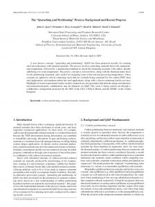
Another major problem is that regions of code that contain jumps whose target is determined at runtime cannot be implemented efficiently in hardware. Assembly code also tends to use many temporary registers in order to implement a highlevel expression. These registers must be removed in order to produce efficient hardware. A major issue with binary-level partitioning is that the results are dependent on the assembly code produced by a compiler or assembly programmer. For example, a compiler may choose to implement a typical move instruction by using an add with an immediate value of zero. This implies that constant propagation must be performed, otherwise an adder would be included unnecessarily. Also, since code and data are impossible to distinguish at the binary level, a partitioning tool must assume that the code is completely separated from data, or must determine dynamically if a location is actually an instruction. As a first attempt at hardware generation from assembly code, we tried binary translation techniques, converting each assembly instruction into a corresponding state in a VHDL state machine. There was little performance to gain from this approach, since most high performance processors have a CPI (cycles per instruction) close to 1. For slower processors, such as an 8051, which have a CPI typically ranging from 4 to 12, this technique may be more effective. The largest disadvantage of this approach is that each time the hardware partition executes, the values of all required registers need to be read by the custom logic. This can add much overhead that in some cases causes performance to decrease. In addition, the area of designs based on binary translation was much larger than a high-level approach. We see that the standard binary translation method imposes much overhead. The main problem with this approach is that translation is done per instruction, and no high levelinformation is used to optimize the hardware. Alternatively, we can use decompilation to recover as much high-level information as possible and thus produce a more efficient hardware implementation. Our hardware generation approach using decompilation is illustrated in Figure 3. This corresponds to the hardware
168
generation component in Figure 1(c). One of the first steps in decompilation is performing data-flow analysis on the assembly in order to remove hardware references (such as registers) and to determine high-level expressions. Data flow analysis is performed through the use of definition-use and use-definition chains. Further details can be found in [11]. Control flow-analysis is generally performed during decompilation in order to recover high-level control statements, such as if statements and loops. At this point, our control-flow analysis consists of only basic block determination. Eventually, we will extend this to detect loops with fixed bounds, so that we can perform loop unrolling and other optimizations. FSM (finite-state machine) scheduling is performed following data-flow and control-flow analysis. We describe the HDL of the region as a FSMD (FSM with data) model. Therefore, FSM scheduling consists of mapping groups of highlevel statements into states in a finite state machine. The most basic example of FSM scheduling is mapping basic blocks into a single state. Scheduling basic blocks to states simplifies the decompilation process because recovery of high-level control statements is unnecessary. Since all control statements jump to basic blocks, they can simply be implemented as state transitions. After FSM scheduling has been performed, the HDL is passed to an RTL (register-transfer level) synthesis tool that creates a netlist. We could simplify the process of hardware generation by converting the assembly to high-level HDL (hardware description language) code and using behavioral synthesis. Since one of the main tasks of behavioral synthesis is to create a finite state machine for the high-level description, this would completely eliminate the need to perform FSM scheduling. However, using behavioral synthesis would require more detailed control-flow analysis in order to recover high-level control statements such as if statements and loops. We have recently begun performing the decompilation process described in [11], converting assembly into high-level VHDL. At this point, the behavioral synthesis tool we use is unable to schedule the loops at the desired clock frequency without having to add extra clock cycles. Type analysis is also generally associated with decompilation. However, since high-level types have no effect on the HDL code, our approach is greatly simplified by ignoring type analysis. Results from the decompilation approach are shown in the right half of Table 2. The most interesting result is that the average speedup is 1.4, nearly the same as the 1.5 speedup from the high-level approach. This is significant because it implies that decompilation-based binary translation can achieve similar speedup as partitioning at a higher level. The energy savings are lower than the high-level approach, averaging 13% savings. The main reason that the energy savings are less than a high-level approach is because of the increased power consumption. This results from a less efficient implementation of the loops in the CSL. When the application is compiled, high-level operations may be transformed into different types of assembly operations and high-level information may be lost. Therefore, when decompilation occurs, the recovered high-level operations may look different than the original code and may be less efficient in hardware. This can result in larger hardware partitions. The hardware for
Figure 3: Hardware generation from assembly using decompilation.
HW Generation Assembly Code Control-Flow Analysis
Data-Flow Analysis
FSM Scheduling
FSMD-based VHDL Code RTL Synthesis
Netlist
*Shaded items refer to decompilation process. the assembly-level partitioning is more than twice the size of high-level partitioning. One area of future work is to transform these high-level operations to achieve a more power-efficient hardware implementation.
6. Conclusions Hardware/software partitioning at the software binary level has many practical advantages important for commercial adoption of the technology. We have shown that such partitioning can compete with traditional source-level hardware/software partitioning in terms of software speedup, thanks to the use of basic decompilation methods. Future work includes using more sophisticated decompilation methods to reduce hardware area and power, to use more aggressive parallelizing techniques found in a few partitioners to achieve more dramatic speedups, and to eventually investigate transparent dynamic hardware/software partitioning.
7. Acknowledgements This work was supported in part by the National Science Foundation (CCR-9876006), UC MICRO, and a Department of Education GAANN fellowship. We thank Jason Villarreal for developing the loop analysis tools.
References [1] G. Aigner, A. Diwan, D. Heine, M. Lam, D. Moore, B. Murphy, C. Sapuntzakis. An Overview of the SUIF2 Compiler Infrastructure. Computer Systems Laboratory, Standford University. [2] Altera Corporation, ARM-Based Embedded Processor PLDs, August, 2001.
169
[3] P. Athanas, H. Silverman: Processor Reconfiguration Through Instruction-Set Metamorphosis. IEEE Computer, March 1993. [4] Atmel FPSLIC, http://www.atmel.com/atmel/products/prod39.htm. [5] V. Bala, E. Duesterwald, S. Banerjia. Dynamo: A Transparent Dynamic Optimization System. Proc. of the ACM SIGPLAN '00 Conference on Programming Language Design and Implementation, 2000, pp. 1-12. [6] A. Balboni, W. Fornaciari and D. Sciuto. Partitioning and Exploration in the TOSCA Co-Design Flow. International Workshop on Hardware/Software Codesign, pp. 62-69, 1996. [7] W. Böhm, J. Hammes, B. Draper, M. Chawathe, C. Ross, R. Rinker, and W. Najjar. Mapping a Single Assignment Programming Language to Reconfigurable Systems. The Journal of Supercomputing, vol. 21, pp. 117-130, 2002. [8] K. Bondalapati, P. Diniz, P. Duncan, J. Granacki, M. Hall, R. Jain, and H. Ziegler. DEFACTO: A Design Environment for Adaptive Computing Technology. In Reconfigurable Architectures Workshop, RAW’99, April 1999. [9] BRASS Research Group, http://brass.cs.berkeley.edu/. [10] The Cameron Project, http://www.cs.colostate.edu/cameron/. [11] C. Cifuentes, D. Simon, A. Fraboulet. Assembly to HighLevel Language Translation. Department of Compter Science and Electrical Engineering, University of Queensland. Technical Report 439, August 1998. [12] C. Cifuentes, M. Van Emmerik, D.Ung, D. Simon, T. Waddington. Preliminary Experiences with the Use of the UQBT Binary Translation Framework. Proceedings of the Workshop on Binary Translation, Newport Beach, USA, October 1999. [13] P. Eles, Z. Peng, K. Kuchchinski and A. Doboli. System Level Hardware/Software Partitioning Based on Simulated Annealing and Tabu Search. Kluwer's Design Automation for Embedded Systems, vol2, no 1, pp. 5-32, Jan 1997. [14] R. Ernst, J. Henkel, T. Benner. Hardware-Software Cosynthesis for Microcontrollers. IEEE Design & Test of Computers, pages 64-75, October/December 1993. [15] D.D. Gajski, F. Vahid, S. Narayan and J. Gong. SpecSyn: An Environment Supporting the Specify-Explore-Refine Paradigm for Hardware/Software System Design. IEEE Transactions on VLSI Systems, Vol. 6, No. 1, pp. 84-100, 1998. [16] R. Goering. Compiler project marks Synopsys' step into post-ASIC world. EE Times, August 28, 2000, http://www.eedesign.com/story/OEG20000828S0020. [17] T. Givargis and F. Vahid, The Platune Platform Tuning Environment, http://www.cs.ucr.edu/~dalton/Platune/, 2002. [18] M. Gokhale, J. Stone. NAPA C: Compiling for hybrid RISC/FPGA architectures. IEEE Symposium on FPGAs for Custom Computing Machines, FCCM '98. [19] J. Hauser, J. Wawrzynek. Garp: a MIPS processor with a reconfigurable coprocessor. IEEE Symposium on FPGAs
[20] [21]
[22]
[23] [24]
[25] [26]
[27]
[28] [29] [30] [31] [32]
[33] [34]
[35] [36] [37]
[38]
170
for Custom Computing Machines, pages 12-21, Napa Valley, CA, April 1997. J. Henkel and R. Ernst. A Hardware/Software Partitioner using a Dynamically Determined Granularity. Design Automation Conference, 1997. J. Henkel, Y. Li. Energy-conscious HW/SW-partitioning of embedded systems: A Case Study on an MPEG-2 Encoder. Proceedings of Sixth International Workshop on Hardware/Software Codesign, March 1998, pp. 23-27. J. Henkel. A low power hardware/software partitioning approach for core-based embedded systems. Proceedings of the 36th ACM/IEEE conference on Design automation conference, pp. 122 – 127,1999. Intel StrongArm 1110 Processor, http://developer.intel.com/design/strong. A. Kalavade and E. Lee. A Global Criticality/Local Phase Driven Algorithm for the Constrained Hardware/Software Partitioning Problem. International Workshop on Hardware/Software Codesign, 1994, pp. 42-48. A. Klaiber. The Technology Behind Crusoe Processors. Transmeta Corporation White Paper, January 2000. Y. Li, T. Callahan, E. Darnell, R. Harr, U. Kurkure, and J. Stockwood, Hardware-Software Co-Design of Embedded Reconfigurable Architectures. Proceedings of Design Automation Conf. (DAC), 1999. A. Malik, B. Moyer, D. Cermak. A Low Power Unified Cache Architecture Providing Power and Performance Flexibility. International Symposium on Low Power Electronics and Design. June 2000. MIPS Technologies, Inc., http://www.mips.com. Proceler, http://www.proceler.com. R. Gupta, G. De Micheli. Hardware-Software Cosynthesis for Digital Systems. IEEE Design & Test of Computers, pages 29-41, September 1993. C. Snyder. FPGA Processors Ready for Takeoff. Microprocessor Report, Novemeber 2000, pp. 25-29. G. Stitt, B. Grattan, J. Villarreall and F. Vahid. Using OnChip Configurable Logic to Reduce Embedded System Software Energy. IEEE Symposium on FPGAs for Custom Computing Machines (FCCM), 2002. Triscend Corporation, http://www.triscend.com/. 2002. G. Vanmeerbeeck, P. Schaumont, S. Vernalde, M. Engels and I. Bolsens. Hardware/Software Partitioning of Embedded System in OCAPI-xl. International Symposium on Hardware/Software Codesign, pp. 30-35, 2001. J. Villarreal, R. Lysecky, S. Cotterell, K. Miller and F. Vahid. Loop Analysis of Embedded Applications. UC Riverside Technical Report UCR-CSE-01-03, 2001. Virtex Power Estimator, http://support.xilinx.com/cgibin/powerweb.pl. M. Wan, Y. Ichikawa, D. Lidsky, J. Rabaey. An energy conscious methodology for early design exploration of heterogeneous DSPs. Proceedings of the IEEE 1998 Custom Integrated Circuits Conference, p.111-117, Santa Clara, May 1998. Xilinx Corporation, Virtex-II Pro Platform FPGA Handbook, January 31, 2002.