The programmability in Reconfigurable Computing comprises all those instances of ... and the MOLEN polymorphic processor [15] respectively. The MOLEN.
Rcosy DES.6392 Reconfigurable Compiler System - Rcosy Towards a Quantitative Model for Hardware/Software Partitioning. Roeland J. Meeuws
Yana Yankova
Koen Bertels
Computer Engineering Laboratory Faculty of Electrical Engineering, Mathematics, and Computer Science Delft University of Technology Mekelweg 4, 2628 CD Delft, The Netherlands E-mail: {rmeeuws,yyankova,koen}@ce.et.tudelft.nl
Abstract In the field of Reconfigurable computing the problem of partitioning a system in hardware and software parts has been tackled in many different ways. Our idea is to devise a quantitative model based on software metrics that are representative for different hardware characteristics. In this paper we research the different estimation and partitioning strategies currently employed in the field as a preparation for developing such a model. We determine that much research has been done on area and speed metrics, while power, memory, and communication aspects have not received much attention. Furthermore, we find that many different partitioning strategies have been developed. Many of which aim to be hill-climbing algorithms, i.e. algorithms that try to find a non-local optimum. Based on the literature we review, we conclude that estimation in a future quantitative model must have a clear notion of error and precision. Furthermore, the use of software metrics as a basis for hardware software partitioning has not been sufficiently explored. On the subject of partitioning strategies, we conclude the need for incorporating the dynamic aspect of reconfigurable computing. Furthermore, partitioning and estimation should be on the same level of granularity. Keywords: Hardware/Software Partitioning, Hardware Estimation, Software Metrics, Reconfigurable Computing
Contents 1 Introduction 1.1 A case study: Software Radio . . . . . . . . . . . . . . . . . . 1.2 Reconfigurable Computing Requirements . . . . . . . . . . . 1.3 MOLEN and Delft Workbench . . . . . . . . . . . . . . . . . 2 High Level Estimation, Metrics, and Profiling 2.1 Area, Speed, and Power . . . . . . . . . . . . . . . . 2.1.1 Area . . . . . . . . . . . . . . . . . . . . . . . 2.1.2 Speed . . . . . . . . . . . . . . . . . . . . . . 2.1.3 Power . . . . . . . . . . . . . . . . . . . . . . 2.2 Other metrics . . . . . . . . . . . . . . . . . . . . . . 2.2.1 Communication . . . . . . . . . . . . . . . . . 2.2.2 Memory Usage . . . . . . . . . . . . . . . . . 2.3 Software metrics and comparability . . . . . . . . . . 2.4 Classifying metrics . . . . . . . . . . . . . . . . . . . 2.4.1 Dynamic vs. Static . . . . . . . . . . . . . . . 2.4.2 Level of design . . . . . . . . . . . . . . . . . 2.4.3 Data structures . . . . . . . . . . . . . . . . . 2.4.4 Strategies . . . . . . . . . . . . . . . . . . . . 2.4.5 Application Domains . . . . . . . . . . . . . . 2.4.6 Use of libraries and component models . . . . 2.4.7 Granularity of Estimation . . . . . . . . . . . 2.4.8 Error in estimation . . . . . . . . . . . . . . . 2.5 Characterizing hardware synthesis and optimization
. . . . . . . . . . . . . . . . . .
. . . . . . . . . . . . . . . . . .
. . . . . . . . . . . . . . . . . .
3 Hardware/Software Partitioning 3.1 Partitioning Algorithms . . . . . . . . . . . . . . . . . . . 3.1.1 Greedy . . . . . . . . . . . . . . . . . . . . . . . . 3.1.2 Simulated Annealing . . . . . . . . . . . . . . . . . 3.1.3 Kernighan-Lin/Fiduccia-Mattheyses . . . . . . . . 3.1.4 Evolutionary or Genetic Algorithms . . . . . . . . 3.1.5 Global Criticality/Local Phase Driven Algorithms 3.1.6 Dynamic Programming . . . . . . . . . . . . . . .
i
. . . . . . . . . . . . . . . . . . . . . . . . .
1 2 3 4
. . . . . . . . . . . . . . . . . .
8 8 8 14 18 21 21 21 22 23 23 24 25 26 28 29 30 31 31
. . . . . . .
33 33 33 35 36 36 38 40
3.2 3.3 3.4
3.1.7 Binary Constraint Search 3.1.8 Clustering Algorithms . . Partitioning and Estimation . . . Dynamic versus Static Solutions Synthesizability and Partitioning
. . . . .
. . . . .
. . . . .
. . . . .
. . . . .
. . . . .
. . . . .
. . . . .
. . . . .
. . . . .
. . . . .
. . . . .
. . . . .
. . . . .
. . . . .
. . . . .
41 42 43 43 45
4 Conclusions
46
References
48
ii
Chapter 1
Introduction For many years, computers have been based on the Von Neumann Machine (or Stored-program machine), which is a machine divided into a processing unit, a combined data and program memory for data, and a sequential flow of data and control elements between the memory and the processing unit [1]. The idea of a program of instructions that are executed sequentially made the implementation of algorithms much simpler, hence the rapid advancement of software development in the following decennia became possible. However, as Backus [2] pointed out, the concept showed an inherent bottleneck, which he called the “Von Neumann-bottleneck”. Because the processing unit and the memory in a Von Neumann-machine are separate, instructions and data have to be moved continually. Furthermore, the sequential nature of this process limits the speed one can achieve by exploiting more parallelism. Still, the Von Neumann-computer has been successful due in no small part to the many tools supporting the paradigm at each level. Moreover, the miniaturization of electronics have provided regular speed improvements (Moore’s Law), diminishing the need for a non-Von Neumann architecture. Despite the dominance of Von Neumann machines, other architectures have been used in specific areas. These application specific systems (ASICs) are able to use the parallelism inherent to the problem at hand and combine processing and storage into their data-path. In contrast to more general applications, application specific systems did not need the programmability and flexibility of the Stored-Program machine. Special languages, tools, and design methodologies have been developed to make the implementation of ASICs possible. In recent years, the continuing applicability of Moore’s Law has come into question. For one, wire delays become an increasing problem at higher speeds, and second, the manufacture of transistors smaller than a few atoms seems unlikely. Furthermore, a growing demand for mobile technology and
1
other systems with limited power supplies have made the use of fast VonNeumann processors in such systems difficult if not impossible. To cope with this problem, designers increasingly use ASICs to speed up expensive algorithms like media encoding and signal processing. Such systems, where both programmable and application specific systems are combined, are called heterogeneous systems. The problem that remains, however, is the inflexibility of such custom hardware, i.e. every different task needs a different circuit. This results in a combinatorial explosion of ASICs, driving up the cost considerably. In order to remedy this problem the research community introduced Reconfigurable Computing (RC). Reconfigurable Computing combines programmable software components with programmable hardware components [3], like FPGAs. Hence, Reconfigurable Computing advances the idea of heterogeneous systems by introducing programmability to the hardware components. These programmable hardware components make it possible to dynamically load different ASIC designs or configurations, making flexible non-Von Neumann machines a possibility. To clarify the concept of Reconfigurable Computing, let us look at [4], where three levels of programmability are identified for both control-flow models (software) and data-flow models (hardware) (Table 1.1). The programmability in Reconfigurable Computing comprises all those instances of programmability. Control-flow Different programs can be executed Executing programs can be modified Dynamic behavior through choice in control flows
Data-flow Different circuits can be executed Executing circuits can be modified Dynamic behavior through choice in data flows
Table 1.1: Three different levels of programmability in control-flow and data-flow systems, as presented in [4]
1.1
A case study: Software Radio
As an illustration of how Reconfigurable Computing can help alleviate processing requirements, while remaining flexible, we will now look into the Software Radio[5, 6, 7, 8, 9]. In mobile communications many different frequency bands are used for different applications, like GSM for voice, GPRS for Internet, and UMTS for video. To make things more complicated the exact frequencies differ per region, for example GSM at 1800MHz in Europe and Asia and GSM at 1900MHz in North America. Because of the different networks, frequencies, and bandwidths, a programmable radio that can service different networks on demand would be beneficial. 2
However, the computing power required for a software radio on a conventional processor are quite high. As an illustration, look at the example in [6], that mentions that processing a 500MHz carrier frequency using a 1 GHz sampling rate (as dictated by the Nyquist theorem) on a 32-bit 4-issue 4GHz system, leaves 32 operations per sample, which is not enough to filter and (de)modulate the signal, apply error correction, and so forth. [6], argues for the use of a heterogeneous multiprocessor architecture, i.e. an architecture that comprises different ASIC and General Purpose processors, to tackle this problem. Nevertheless, such an approach may be expensive. [7, 8] suggests Reconfigurable Computing (especially FPGA technology) as a means to make radio signal processing possible, while remaining flexible enough to service different networks at different times. In [8] we even find an example design: the Layered Radio Architecture.
1.2
Reconfigurable Computing Requirements
Although the advantages of Reconfigurable Computing are clear, it has not pervaded industry as traditional computing has. In an attempt to explain this, [3] argues that while the Von Neumann Machine is supported by an extensive and mature base of tools, apis, and design methodologies, no such extensive support is available for the Reconfigurable Computing paradigm. In other words, for Reconfigurable Computing to be commercially applicable, it should have a comparable support base. In recent years some tools have been developed to attack this problem. The problem doesn’t end there, however. Because Reconfigurable Computing moves away from the von Neumann model, the extensive base of support should be adapted accordingly. In [10], for example, current hybrid programming models are pointed out to be immature, because FPGAs and CPUs are treated completely separate. In order to make the design of Reconfigurable Computing systems feasible the paper proposes a more transparent model, i.e. the multi-threading model. This model provides a way to describe concurrency without specifying where the thread will be implemented. A separate partitioner can then partition the threads over the hybrid processing elements. In [11] this model is elaborated in more detail. The paper describes how to implement software and hardware threads by using a common abstraction layer in the operating system, providing a common interface between hardware and software threads. Another possible programming model for reconfigurable computing is presented in [12], where a functional programming model, called V, is introduced. That model uses implicit parallelism and aims to be similar to both traditional embedded (compositional) functional models, as well as more component based models used in hardware design. Computational models need to be redefined with respect to Reconfigurable Computing as well. In [13] a redefinition of
3
the term algorithm, as used in computability theory, is presented tailored to Reconfigurable Computing.
1.3
MOLEN and Delft Workbench
Our research group has been working on reconfigurable computing for some time and we have developed a reconfigurable programming paradigm, with an accompanying platform, called the MOLEN programming paradigm [14] and the MOLEN polymorphic processor [15] respectively. The MOLEN programming paradigm features parallel hardware and concurrent hardware processes, but is intended to be sequentially consistent, i.e. the result must be the same as when the program would have been executed sequentially, and is targeted at single-program execution. As these papers mention, this paradigm has been developed to cope with 4 problems commonly associated with reconfigurable computing: • Opcode space explosion If new instructions are defined for every (every) configuration on a reconfigurable platform, a potentially unlimited amount of opcodes are needed to be able to implement a broad number of applications, however, a typical architecture has only a limited amount of unused opcodes available. • Limitation of the number of parameters Several reconfigurable computing approaches offer only a limited amount of input and output parameters. The maximum amount of parallelism that can be attained, therefore, is limited too. • Lack of parallel execution support Many architectures don’t facilitate executing sequential data-independent operations or configurations in parallel. • Lack of modularity The configurations used in reconfigurable systems are often specific to a certain platform or technology. This makes it quite laborious and thus expensive to port configurations to another platform. In order to provide solutions for these problems the MOLEN programming paradigm suggests a limited instruction set extension. This extension provides instructions to load and execute configurations, a large register set for parameter passing, and the possibility to execute different configurations on the reconfigurable unit in parallel. Loading configurations is implemented using configuration microcode, which is code that performs the actual configuration. This way different types of reconfigurable units can be configured without the need for changing 4
the MOLEN architecture providing a much needed degree of modularity. A so-called SET operation is defined that loads the configuration microcode and initiates the configuration procedure. When a configuration is completed the added functionality can be executed using an EXECUTE instruction. The EXECUTE instruction uses one opcode in the base opcode space and provides 2( n − o) (where n = no. bits per instruction, o = no. of bits per opcode) additional configured operations, addressing the problem of the opcode space explosion. The EXECUTE instruction loads an execution microcode program into the reconfigurable unit. This program is then executed using the configuration previously loaded by the SET operation. Multiple available configurations may be executed in parallel. Explicit synchronization among the core processor and the different configurations can be performed using the a special instruction (BREAK). Before the EXECUTE instruction can commence, however, the necessary data should be provided to the register set in the MOLEN architecture responsible for parameter passing (XREGS). Therefore, instructions (MOVTX, MOVFX) for moving data between the core processor and memory on one hand and the core processor and the XREGS on the other have been added as well.
Figure 1.1: A basic overview of the general MOLEN platform. The basic structure of the MOLEN platform is depicted in Figure 1.1. First instructions are fetched from memory and partially translated by the arbiter in order to decide whether they are redirected to the core processor or the reconfigurable unit. The reconfigurable unit comprises of a reconfigurable microcode unit or ρµ-code unit and a custom computing unit (CCU). The ρµ-code unit interprets and executes the configuration- and execution microcode, and the CCU is the actual configurable hardware part, e.g. a 5
FPGA. We have already established the need for extensive tool support when considering the acceptance of reconfigurable computing in industry. Tool support and integration for reconfigurable computing is the main focus of the Delft Workbench project. Its research covers the entire design process from code profiling to compilation. The project has four main objectives [16]: • Program Analysis and Performance Prediction The Delft Workbench aims to identify functions in a program that might benefit the most from hardware implementation. These functions are then characterized by performance and area metrics, in order to find a set of functions with optimal increases in performance given the constrained area of the target platform. The result is a (semi)automatic selection of a set of functions for migration to hardware. • C-to-VHDL mapping In order to implement software functions in hardware, a designer would traditionally translate them to VHDL manually. Within the Delft Workbench, effort is being made to automate this process. One example of such automation is the C–to–VHDL compiler, that is being developed. It can translate C programs or candidate functions to VHDL. A problem with such a compiler, however, is the lack of interactive design space exploration it allows. For this purpose Delft Workbench envisions a library of FPGA configurations with an accompanying performance model, which helps the designer evaluate different design alternatives. • Retargetable Compiler When a set of candidate functions is determined, the Delft Workbench provides a retargetable compiler that can compile these functions to a MOLEN architecture. Functions are translated to code for configuring the FPGA, moving the needed parameters, starting the execution, and retrieving the output. The compiler must deal with all compilation issues for the GPP as well as the added difficulties introduced by adding a reconfigurable unit. • Integration and Validation The output of the retargetable compiler can now run on a real MOLEN implementation, allowing actual performance statistics, like FPGA reconfiguration time, to be obtained. These statistics are used as feedback for the Delft Workbench tool-flow. A refined set of candidate functions and a refined schedule are determined using the feedback information. This process iterates until the designer is satisfied with 6
the results. The iterative nature of the process implies a tight coupling among the different tools in the tool-flow.
Figure 1.2: A basic overview of the general Delft Workbench tool-flow. The Delft Workbench project focuses mainly on the MOLEN programming paradigm as its target platform. The tools and tool-flow envisioned by Delft Workbench are depicted in Figure 1.2. At the moment partitioning of a program for the MOLEN platform is still manual. The Delft Workbench project proposes a code profiler and partitioner that automate this task. The goal of this profiler/partitioner is to increase the speed of the application, while staying within the bounds on the limited area of the reconfigurable unit. In order to decide where parts of a program should reside, the Delft Workbench specifies the need for a decision model based on metrics collected during profiling. Currently, no such model exists. Therefore, in order to develop such a model this paper investigates different metrics, estimation strategies, partitioning models, and partitioning strategies. The paper is organized as follows. In Section 2 I will discuss metrics that indicate hardware aspects of a (part of a) program and estimation techniques to determine them. Then, in Section 3 I will review hardware/software partitioning models and strategies. Finally, in Section 4 I will briefly discuss the results presented in this paper and indicate possible elements for the decision model to be used in the code profiler/partitioner in Delft Workbench.
7
Chapter 2
High Level Estimation, Metrics, and Profiling Estimation of different cost parameters has always been an important activity in high level system design. Estimates of e.g. speed, area, or power inform a designer about whether a design will meet requirements, stay within budget, and so forth, thus driving further design choices. Not only cost parameters can be important measures to a designer, others, like loop frequency or data reference locality, might help direct the design process as well. Many tools and algorithms have been developed over the years that help determine metrics and thus make the job of the designer easier. If we go one step further and model the process of selecting candidates for hardware implementation, we need to look at the measures and their meaning. In this section we will discuss different metrics and techniques to estimate them. First I will briefly present the different papers I reviewed. Then, I will review different aspects of the estimation schemes by finding ways to classify these metrics. Furthermore, we will briefly go into synthesis and optimization and how we may measure its effects.
2.1
Area, Speed, and Power
Most work in estimation has focused on area, speed-up, and power, probably because they directly correspond with the cost and obvious requirements of designs. We will discuss them here first, before we go on to less obvious areas of estimation.
2.1.1
Area
Area estimation has been tackled in various ways by different groups. In [24] a lower bound on area is estimated under certain performance constraints. Specifically, they estimated the number of modules of each type and the area 8
Paper
Dynamic/ static
Level of design
Application Domain
Data structure
[17]
Static
Behavioral
Multimedia
CDFG
[18] [19]
Static Static
Behavioral Behavioral
Communication Custom Multimedia CDFG
[20]
Static
System/ Behavioral
[21]
Static
Behavioral
Multimedia, Mathematical Multimedia, General Purpose
[22]
Static
RTL and lower
n/a
[23]
Static
Behavioral
[24]
Static
Behavioral
Multimedia, Compression, Mathematical, General Purpose, Cryptography Multimedia
[25]
Static
Behavioral
n/a
[26] [27]
Static Static
Cryptography Multimedia
[28]
Static
Behavioral System/ Behavioral Behavioral
[29]
Dynamic
System
Node model
Granularity
Strategy
Complexity
Error
multiple (non)linear models n/a Bit-width based
Entire Graph
Hierarchical
linear
2.5%-10%
Functions Entire Graph
Incremental Neural
O(1) per iteration nonlinear
VHDL Abstract Syntax Tree PACT HDL Abstract Syntax Tree Boolean expressions CDFG
Bit-width based
Entire Application
Scheduling
nonlinear
about 7% 10% large error with badly trained networks 16%
Simple
Entire Application
scheduling, allocation
nonlinear
average 25% (maximum of 241%)
n/a
n/a
Complexity
linear
within 56%
unknown
Entire Graph
Hierarchical
linear
60–100%
DFG
Simple
Scheduling
O(nc2 )
n/a
(annotated) CDFG n/a H-CDFG
Simple
scheduling
n/a
Hierarchical Hierarchical
O(speedest.) + O(n2 ) n/a O(n log n)
Multimedia, (C)DFG General Purpose Communication (annotated) DFG
Simple
Entire Graph Entire Graph n/a Entire Graph Node clusters
Hierarchical
linear
n/a
Entire Graph
Scheduling
O(simulation)+ O(n2 )
n/a
Simple Simple
Bit-width based
Table 2.1: Different classifications of area estimation found in several papers and indications of estimation error in those papers. For an explanation of the classifications, please refer to Section 2.4. needed for interconnect. The paper explains how lower bound estimates can be determined by scheduling a DFG and accounting for the minimum number of modules and busses required. Because area estimation tries to predict the results of synthesis tools, [21] tries to find estimates by mimicking high level synthesis. Techniques like force directed scheduling, resource allocation, operation assignment, and interconnection binding, all come from high level synthesis. The algorithm uses a simplified model of an FPGA only taking into account standard LUTs and multiplexers as interconnection structures. Furthermore, optimizations during synthesis are not taken into account. Although these simplifications make the estimation process considerably faster, they also reduce the accuracy of the result. Where some area estimation techniques aim to be deterministic and are based on knowledge about synthesis, the neural estimator (NESTIMATOR)
9
n/a n/a
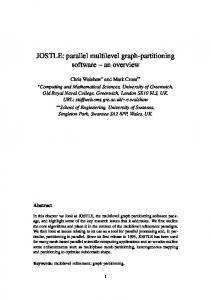
Figure 2.1: The NESTIMATOR neural estimator from [19] working together with a synthesis tool. The results of synthesis are compared with estimates and the neural network is adapted accordingly.
10
in [19] takes a more non-deterministic approach. The estimator in this paper is first “teached” to correlate characteristics of a behavioral design to synthesis results by providing it with hundreds of examples. The setup is depicted in Figure 2.1. The feed-forward neural network used in this paper consists of 4 layers of neurons. The hidden layers use non-linear sigmoid neurons and the output layer uses linear neurons. The input to the neural network are several metrics characterizing CDFGs: • Number of allowed time steps • Maximum allowed clock period • Average delay and area and variances of each FU type • Number of nodes using each FU type • Number of nodes • Average bit-width of nodes and variance (indicates node and interconnect area) • Average path length and variance (indicates interconnect area) • Average number of inputs/outputs and variance (indicates interconnect and controller area) • Average minimal and maximal lifetime of outputs and variances (indicates storage cost) • Complexity of the CDFG (indicates parallelism) An approach targeted specifically at partitioning algorithms is introduced in [18]. This paper describes how a preprocessed information data structure holding basic design information can be maintained between succesive iterations making it possible to get an updated estimate of the area during every new iteration of the partitioning algorithm in constant time. [30] demonstrates the usefulness of incremental estimation by integrating the technique into the COSYN algorithm. Another approach concerning estimation during the partitioning process is defined in [25]. Here the optimal cost of a given partitioning for the minimal execution time is calculated. The optimal cost is determined by adding the costs of single nodes while accounting for the sharing of resources. Resource sharing is represented by the sharing factor which is based on the similarity between nodes. Similarity may be defined in multiple ways, but must indicate to what level nodes can share hardware. In [23] the estimation is executed before the partitioning process and therefore tries to be independent of specific synthesis tools. Because of this, 11
the approach taken in this paper only takes into account the data paths. The estimates are used in a cost function in a partitioning algorithm and only need to be indicators of the actual area. This means that, although disregarding the control paths does result in a significant error, the metric can still be applied in partitioning. As part of the fine-grained and coarse-grained partitioning strategies targeted specifically at FPGAs in [28] the authors present an area estimation approach. The partitioning strategy utilizes an area estimation algorithm that is based on summation. However, this summation handles computation area and storage area separately. This way the different logic used for storage (flip-flops) and computation(LUTs) is more accurately represented in the estimate. Pattern type(s) Constant Linear Quadratic Bi-product
Multi-linear2
Node
Formula INPUT, OUTPUT Unsigned ADD and SUBTRACT (Un)signed integer MULTIPLICATION (Un)signed multiinput ADD and SUBTRACT multi-input AND or OR
y=C y = p0 + p1 n y = p0 + p1 (n − p2 )2 y = (m − p0 )(n − p1 ) + p2 y = p0 + (p1 ∗ x/2)(z/2 − 1)
Table 2.2: Bit-based area models of the main operators in LUTs, as mentioned in [17].(y=area(LUTs), n=bit-width, m=inputs, pi = experimentally determined constants)
In an effort to guide optimizations in an SA-C compiler [17] introduced an area estimation technique that captures the impact of compiler optimizations to the area of a design. The estimator executes between the optimization and synthesis phases. Because the estimator is targeted at a specific compiler, the estimator can use detailed characterizations of the nodes in the DFG, depicted in Table 2.2. The estimate is further refined by looking for common patterns of synthesis optimization, and adjusting the estimate accordingly. Instead of estimating the resource utilization of an entire design, some papers try to estimate the impact of specific aspects of a design. In [31], for example, we encounter a way to estimate the effect of loop unrolling on the area. The approach models pipelining and full- and partial unrolling of loops and this way accounts for an increase of the number operators and coarser 12
grain array indexing. The paper mentions that unrolling of outer loops, loop strip-mining, loop merging, and optimizing loop-unrolling side-effects should be investigated to make the estimation more accurate. A narrower approach focussing only on boolean functions is presented in [22]. It demonstrates the use of a complexity measure in estimating the area of high level descriptions. This complexity measure is based on the sizes and probabilities of prime implicants in the on-set of boolean functions and shows an exponential relation with the area needed to implement the functions. This relationship is the basis for the area estimation in this paper. Estimating area specifically from software oriented languages like C or Matlab has been covered in several papers. The researchers in [26] tried to base the area estimation on extracting relevant operations from the source code, matching modules from a library to the operations, and use timing information to find out where resources can be shared. The accuracy of this approach was somewhat disappointing, because • the authors of [26] did not use the impact of the control logic in the area estimation • the approach did not account for optimizations • the algorithm needs the C description to have a hierarchy close to the hierarchy of the final design. Using Matlab specifications as a starting point [29] uses simulation to obtain execution traces that drive the estimation process. The traces are used to build a DFG of the program. Together with an FPGA performance model that determines the characteristics of specific operations based on bit-width and clock speed, the DFG is used to estimate the area required by the Matlab code. The authors have chosen to use an area/latency grid to schedule the DFG before estimation. Using this approach they try to account for resource sharing and area constraints at the same time. As a part of the research around the MATCH Compiler [32] the authors of [20] present an area estimator to provide the compiler with information for automatic design space exploration. The estimation comprises counting all operations and registers and uses a simple heuristic formula (Equation (2.1)) to calculate the number of CLBs that is needed for a design. NCLBs = 1.15 ∗ max(Nf /2, Nr ) Nf : # of function generators Nr : # of registers
13
(2.1)
The algorithm uses a library to count the number of function generators used by the operations. To get more accurate estimates. the paper describes a type refinement pass, which determines the bit–widths needed for each variable and operation before estimation. The authors of [27] introduced an estimation technique where an entire trade-off curve is calculated. Their algorithm uses H-CDFGs, which are CDFGs with other CDFGs as nodes. From the bottom levels of the H-CDFG up, the CDFGs are scheduled and resources are allocated using different time constraint values. Calculation of the total number of required resources of multiple CDFGs is based on several heuristic and deterministic summation rules that account for resource sharing.
2.1.2
Speed
In order to get an approximation of the performance of a design, the research community has proposed many ways of estimating latency and speed–up. Performance measures like these can indicate if a design is within performance constraints and can drive hardware/software partitioning. An example of latency estimation can be found in [24] for example. Apart from estimating area, this paper also presents a way to calculate a lower bound on latency given certain resource constraints. The lower bound is based on the critical path latency and depending on the resource constraints is increased by the extra delay of every module on the critical path due to module constraints. In [25] the latency of a hybrid hardware/software system is estimated by determining the critical path of a Co-design graph as defined in the same paper. The Co-design graph is a task graph with annotated nodes and edges. For latency estimation the nodes are annotated with latency information and for edges the graph records whether they are software or hardware edges and whether they indicate a control or a data dependency. The critical path is then determined by finding the longest path in the task graph. As with area [27] tries to estimate entire trade-off curves for the latency of a design using different timing constraints. Again the H-CDFGs are traversed in a bottom-up fashion and the latency is calculated at every level by accounting for the allocated resources due to the timing constraints. The COSYN [30] and CRUSADE [36] co-synthesis algorithms estimate finish times of tasks with the longest path algorithm. Described in [30] the algorithm finds the longest path in a DAG taking in to respect both the execution and communication times of tasks and links respectively. The partitioning algorithms in [28] discussed earlier, also estimate latency by first determining the longest path. This preliminary value is then 14
Paper
Dynamic/ static
Level of Design
[33]
Static
[29]
Dynamic
Instructionlevel System
[20]
Static
System/ Behavioral
[24]
Static
Behavioral
[34]
Dynamic
Behavioral
[25]
Static
[35]
Static
Behavioral (during partitioning) Behavioral
[30]
Static
[36]
Static
[27]
Static
[28]
Static
[37]
[21]
Application Domain
Data structure
n/a
Node model
Granularity
Strategy
Complexity
Error
Intermediate code Communication (annotated) DFG Multimedia, VHDL AbMathematistract Syncal tax Tree Multimedia DFG
n/a
Application
Complexity
n/a
Bit-width based Bit-width based
Entire graph Entire Graph
Scheduling
O(simulation)+ 10% nonlinear linear 13%
Simple
entire graph
Scheduling
Multimedia, Cryptography, Compression, General Purpose n/a
n/a
n/a
Loops
Simulation
(annotated) DFG
Simple
entire graph
Scheduling
O(n2 log n)
n/a
Communication n/a
Bit-width based
Complexity
n/a
n/a
Behavioral (during partitioning) Behavioral (during partitioning) System/ Behavioral
n/a
Task graph
Simple
Functions (=Occam processes) Entire graph
Incremental
linear
n/a
Communication Task graph
Simple
Entire graph
Scheduling
linear
n/a
Multimedia
H-CDFG
Simple
Entire Graph
O(n log n)
n/a
Simple
Node ters
n/a
n/a
Hierarchical Loop Graphs
n/a
Loops
Simulation
O(simulation)+ n/a O(1)
Static
Behavioral
Multimedia, General Purpose Multimedia, Cryptography, General Purpose Multimedia, General Purpose
(C) DFG
Dynamic
Behavioral (during partitioning) Behavioral
Hierarchical, Allocation (bipartite matching) Scheduling
PACT HDL Abstract Syntax Tree
Simple
Entire Graph
Scheduling
nonlinear
Scheduling
clus-
O(nc2 ) n/a (c: time steps) O(simulation)+ n/a O(1)
Table 2.3: Different classifications of speed estimation found in several papers and indications of estimation error in those papers. For an explanation of the classifications, please refer to Section 2.4. refined by adding the latency of moving input and output values from and to memory, the latency of transferring data over partition boundaries, and the latency due to synchronization between tasks. Area estimation from Matlab code as presented in [29, 20] was already discussed in the previous section. These two papers also describe delay estimation techniques. In [29] the critical path is used as latency estimate. If area constraints introduce extra delays on the critical path, the latency estimate is changed accordingly. The authors of [20] take a more elaborate approach. They split the delay estimation between estimating the critical path delay and the interconnection delay. The delay of single tasks on the critical path are not retrieved from a normal library, but are calculated using generic delay formulas describing functional units and using fan–in and bit width as inputs. Libraries can become more compact this way. In general the paper models the delay 15
8%
n/a
of an operation with Equation (2.2). i=nf an−in
δ = a + bnf an−in +
X
ci mi
(2.2)
i=0
mi : bit-width of input i nf an−in : number of inputs a, b, ci : experimentally determined constants Using estimates for average interconnection length and physical FPGA wire lengths, the algorithm determines the average number of physical wires and programmable interconnect points and therefore the average interconnection delay. Instead of determining a value for the latency of a design, papers [34, 37] use a temporal profile of a software program to determine the maximum speed-up that can be obtained by moving certain parts of the program to hardware. The more a function, for example, contributes to the total execution time of a program, the larger the potential speed-up when it is moved to hardware. However, [34] mentions that based on the examined programs a) almost 100% of the candidates for hardware implementation contribute 1% or less to the total execution time and b) memory access time and memory access rate have a significant impact on the performance gain that can be achieved. [37], on the other hand, puts the former comment in perspective by pointing at the 90-10 rule, which states that 90% of the execution time is spent in 10% of the code. It goes on to examine the validity of this rule and concludes that many application do indeed exhibit this behavior. Finally the paper presents a simple formula to calculate the expected speed up of partial hardware implementation based on loop frequency. In an attempt to define a performance measure that makes it possible to compare hardware and software performance during Co-simulation, [35] describes using the CPI of OCCAM-II to indicate performance. The paper describes how to calculate the CPI for software-bound processes and how hardware-bound processes can be characterized by a so-called equivalent CPI. Both measures use a parameter that depends on the architecture, compiler, synthesis tool, and scheduling policy. These measures have to be determined for every new architecture that needs to be simulated. The hardware measure utilizes bit-based operator models to estimate timing characteristics. The models of the main operators is depicted in Table 2.4. The algorithm in [21] measures the speed-up of a design by counting the number of control steps that are present in the control nodes in a CDFG and the number of times they are executed. Then it applies different formulas for hardware and software to obtain the execution times of both implementation alternatives. Simply dividing these yields the speed-up factor. 16
Operation + +
Architecture Ripple carry CCLA(n/p2 ) p = BCLA dimension
* * / / /
Baugh Wooley Bisection Restoring (Dean) Non-Restoring (Guild) Non-Restoring with 2-level CLA and Carry-save (CappaHamacher) Non-Restoring with 1-level CLA and Carry-save (CappaHamacher)
/
f (δ, n) 2nδ if(n = 1)11δ else 11δ(10 + log p(1 + n(n/4 − 1))(n/4 + 1) if (n = 1)2δ else 4nδ if (n = 1)2δ else 4nδ (3n2 + 1)δ 3(n + 1)2 δ (11n + 12)δ
(9n + 10)δ
Table 2.4: Bit-based timing models of the main operators as mentioned in [35]. The µ–profiler as described in [33] uses the number of cycles gained by hardware implementation to drive the discovery and selection of custom instructions for ASIP designs. Both the decrease in computation cycles by moving a pattern in the intermediate code of an application to hardware and the frequency of that pattern contribute to the measure. The author admits this measure is crude, but argues it is useful for early discrimination between potential candidates for hardware implementation and patterns with insufficient prospect for speed gains. In the future this measure may be improved by accounting for ILP, pipelining, and other software optimizations. One such optimization, i.e. loop unrolling, is specifically studied in [31]. We already discussed how the authors of this paper estimate area in the previous section and speed–up is handled in the same way. Results, however, show a larger discrepancy between estimates and measurements for speed–up, than for area. The authors explain how this might be caused by e.g. unbalanced pipeline stages due to resource constraints or other loop optimization side-effects and mentions that the underlying model of the algorithm should facilitate more complex algorithms that do account for these effects.
17
2.1.3 Paper
[38]
Power Dynamic/ static
Level of Design
Application Domain
Data structure
Node model
Granularity
Strategy
Complexity
Error
Behavioral
Communication, CDFG, General state Purpose transition graph
Activitybased model
Entire Graph
Hierarchical
O(simulation)+ 11.8% nonlinear
[39] [30]
Static (dynamically determined input probabilities) n/a Static
System Behavioral
n/a n/a
n/a Task graph
n/a Simple
Complexity Hierarchical
n/a linear
n/a n/a
[27]
Static
System/Behavioral Multimedia
H-CDFG
Simple
n/a Entire Graph Entire Graph
Hierarchical, Allocation (bipartite matching)
O(n log n)
n/a
Table 2.5: Different classifications of power estimation found in several papers and indications of estimation error in those papers. For an explanation of the classifications, please refer to Section 2.4. In order to increase battery lifetime in mobile and embedded systems, reduce heat dissipation in high performance designs, etc. many researchers have sought to estimate the power usage during system design. In [40], for example, we find a taxonomy of several power estimation techniques at different levels. At the highest level the authors discern several design levels at which power can be estimated. For each level the authors further classified the estimation strategies as depicted in Table 2.6. The different levels in the taxonomy also correspond to the design process. At the early stages power intensive parts can be identified with system-level estimation. Later on when a behavioral description is available, instruction- and behavioral level estimation can help guide the partitioning process and optimization of software and hardware parts. Finally, before actual synthesis is performed, architectural estimation can help choose from different architectures. The system-level partitioning algorithm in the TOSCA co-design environment [41] uses several power evaluation metrics to drive system level partitioning. In order to choose the best design alternative several metrics indicative of good power performance for different types of operating modes are proposed in [39]. The different system characterizations are: • Fixed Throughput Mode These systems are characterized for power by the Power to Throughput Ratio, which is the same as energy per operation. This metric is applicable to e.g. DSP applications. • Maximum Throughput Mode In these systems power is characterized by the Energy to Throughput Ratio. Energy and throughput, in this case, mean maximum energy per operation and maximum throughput respectively. Microprocessorbased systems are an example of these systems. 18
Table 2.6: Taxonomy of power estimation techniques as presented in [40]. • Burst Throughput Mode Systems that only perform in bursts can be characterized by a modified Energy to Throughput Ratio. Energy in this case the energy during computation and the energy during idling per total number of operations. Systems with user-interaction are often in burst throughput mode. • Area-Constrained Systems Two metrics are proposed that can characterize Area-Constrained systems: The Power by Area Product, which allows to optimize for power, and the Energy by Area Product, which allows for optimization of area and power together. Many designs will have some degree of limitation for area. Apart from presenting these metrics the paper also argues that communication between hardware and software parts contributes significantly to the power consumption of the design. When off-chip busses are involved this contribution can be even higher. In order to estimate the power used by communication from the hardware, TOSCA calculates the bus switching activity using the bus width, required bandwidth, and the encoding scheme for data and addresses. An example of static power estimation at the behavioral level, as discussed in [40], is presented in [27], along with area and speed estimation techniques, discussed earlier. The paper estimates trade-off curves for power 19
Switched Capacitance Matrix The m-input n-bit module depicted on the left has a corresponding m × n matrix of switching activities for each bit. The module capacitance can then be estimated with Equation (2.3). Cmod =
m X n X
aij × cij
(2.3)
i=1 j=1
aij and cij are respectively the activity and a module-dependent constant for bit j of input i. The constant is determined by switchlevel simulation of the module and the activity represents the probability that the bit will change between successive states.
Figure 2.2: Module power model used in [38]. consumption against varying timing constraints. The power estimation differs from the area and time estimation by taking into account the execution frequencies of functional units and the clock frequency. The authors of [22] use the area prediction method discussed in the previous section together with estimates of the average node switching activity and gate capacitance. Problems with their approach are the need for additional estimators for switching activity and the restriction to single-output boolean functions. The contribution of control-flow circuits to the power consumption of a system is often assumed to be negligible. This may be a fair assumption for data-flow systems, but for control-flow intensive designs this aspect must be considered during power estimation. One such approach can be found in [38]. This particular approach utilizes both STGs annotated with branch probabilities and CDFGs. Using a generic model for modules all edge capacitances are calculated using the probability of each state and each transition. Special probabilities are calculated in the presence of loops. Furthermore, the paper describes how the capacitance of the controller itself is estimated with a simple formula based on the number of states in the controller. In the COSYN-LP algorithm [30] energy levels of tasks in a task graph are estimated by using execution and communication time as starting points. The energy level of a task is then estimated by adding the energy for all fan20
out edges and all preceding nodes to the tasks own energy level. This process starts from the bottom at the sink nodes and progresses upwards via the fan-in edges. If after partitioning multiple allocations have the same power level, an alternate estimation strategy is used, where different heuristics are used for processors, FPGAs and links.
2.2
Other metrics
In Section 2.1 we discussed various methods of estimating the more obvious aspects of hardware design. In the last decade, however, other aspects like memory usage, communication, and design complexity have also been researched as possible driving forces for system design. We will now briefly review some of these metrics and their uses.
2.2.1
Communication
Estimating the amount of communication is also present in some area, speed, and time estimation techniques (e.g. [24, 21, 20, 30, 39, 28]), and not without reason: communication requires interconnect circuitry, requires a fair amount of power, and introduces communication delays into the design. Therefore, accurate communication estimation can be a valuable asset to any system designer. A more focused effort to estimate the communication latency can be found in [23]. This paper specifically estimates the communication between hardware and software segments in a hybrid system. They assume a shared memory model is used for communication between hardware and software and also that communication with hardware only occurs with adjacent hardware modules. The latter is a fair assumption in case of data-intensive designs. Another paper on communication is [42]. In this paper we see how the amount of communication can be represented by the sum of all edge weights, or Total Edge Weight(TEW). As edge weights the paper uses the amount of data transfered along the edges (in bits).
2.2.2
Memory Usage
Few hardware-oriented memory usage estimation strategies have been proposed, but in e.g. [34], we can see that memory usage can have significant impact on the speed of a design. Furthermore, communication with the memory system and refreshing of volatile memory can impact power usage. And finally, memory modules, extra interconnect, and memory management
21
circuits require area. As with communication it seems clear that memory estimation can be very useful to a designer. While many software profilers measure or characterize memory usage [39, 43, 44, 45] and some hardware/software partitioning algorithms [28, 36] take into account memory aspects of a design, to the best knowledge of the author there has been little research into memory usage in hybrid architectures. One example of memory size estimation for hybrid architectures can be found in [46], where the size of individual data dependencies is estimated. The described algorithm focuses mainly on dependencies between loop iterations and requires single-assignment code, but it does give valuable information on memory size even in the early stages of design, when only a partially fixed execution ordering is present. The authors of [47] point out the difficulty of hardware synthesis of programs with pointers. Traditional context-insensitive pointer analysis does not suffice. To answer this problem the paper describes a context-sensitive method of analyzing pointers in a program based on symbolic transfer functions. These functions capture how a function influences the program state. The program state and the symbolic transfer functions are represented as boolean expressions. The pointer analysis scheme presented utilizes binary decision diagrams to speed up the analysis, making context-sensitive pointer analysis feasible. In [45] we find a study on reference locality in software programs resulting in some metrics that characterize data reference locality in a program. These metrics are based on hot data streams derived by bursty tracing [44]. Originally targeted at cache optimization on modern processors, this information may also help optimize local memory utilization in hybrid architectures or help decide whether a function can be efficiently implemented in hardware, because a function with an intensive and erratic memory access pattern might not benefit from hardware implementation at all.
2.3
Software metrics and comparability
In defining a candidate selection model for hybrid architectures not only hardware metrics are important, but also software metrics. In previous sections we have already discussed software measures that may also describe hardware aspects ([45]) or may indicate code most susceptible to optimizations ([37]), but software measures also make comparisons of hardware and software implementations possible. In [48], for example, we find software energy models that enable the authors to compare different hardware / software partitions. There are some problems with such comparisons, though: • Differences in precision The precision of a software/hardware measure might be less accurate 22
than its hardware/software equivalent. This means comparisons are only as good as the least accurate measure. • Differences in algorithms Different measures are often determined using different algorithms, which makes it unclear if they are comparable in a straightforward way. Look, for example, at cyclometric complexity; it’s not at all clear if software (C) and hardware (VHDL) cyclometric complexity are equivalent or comparable.
2.4
Classifying metrics
Having discussed different estimation strategies and metrics for several aspects of a design we now move on to classification. In the following few sections I will discuss different aspects of the presented metrics and estimation strategies, and explore possible classifications.
2.4.1
Dynamic vs. Static
One aspect of estimation strategies is whether they try to analyze a design statically, at compile-time, or dynamically, at run-time or during simulation. In the following we will refer to these as static estimation and dynamic estimation respectively. From the papers discussed so far it seems static estimation has been dominant in the field of hardware/software partitioning and hardware synthesis. We can explain this if we take into account the many iterations partitioning algorithms may go through. If every iteration performs a potentially expensive simulation, partitioning can take a long time. This suggests that static estimation techniques aim to be fast more than they aim to be accurate. Static estimation is also the dominant strategy in area estimation. Because area is almost always assumed to be fixed during run-time, this is only logical. When we look at hybrid architectures, however, the assumption that area is fixed during run-time does not have to apply. Future area estimation could take advantage of simulation to get dynamic area profiles. Power estimation is often based on area estimates or area estimation techniques and thus power estimation, too, is mostly based on static estimation. In [40], however, we do find some cases of dynamic techniques like dynamic behavioral activity-based estimation (Table 2.6). Power consumption, especially that of control-intensive designs, depends on the input of an algorithm as well as the implementation itself. Therefore dynamic estimation can be useful for reasoning about power in designs. The few dynamic estimation strategies discussed so far [34, 37, 29, 45, 40] all concentrate on speed and memory usage. These characteristics are often
23
dependent on the input and change during run-time. Still, hardware estimation mainly focusses on static estimation. If we look at software profiling and estimation, however, we find more dynamic techniques. It seems dynamic estimation techniques are more suitable for control-intensive designs, while static estimation is more suitable for data-intensive designs.
2.4.2
Level of design
Different estimation techniques require different levels of detail in a design and have various levels of accuracy. Therefore, it is useful to categorize estimation according to the design step it is targeted at. We have already seen a similar taxonomy for power estimation techniques in [40]. It is not the aim of this paper to present an exhaustive study of system design steps, therefore we will use a simplified model of system design as a tool for discussing estimation. We discriminate three levels of design: System level, Behavioral level, and RTL/Instruction level. As can be seen from the Figures 2.1, 2.3, and 2.5, the behavioral level is the predominant level in the reviewed papers. This is mainly because the papers were selected based on their relevance to high level synthesis. 1. System level In the early stages of design a lot of high level decisions have to be made in a relatively short time. In order to give the designer information on different design alternatives, fast system level estimation is necessary. While, in this phase accuracy is not very important yet, estimates should be indicative of actual values. On the system level components are not yet (fully) specified using behavioral descriptions, or are modeled by a mathematical model. Papers on the MATCH compiler for Matlab models, for example, are considered to be on the system level in this view. 2. Behavioral level Later on in the design process system components will be refined with specific functional descriptions. This is the phase where many hardware/software partitioning algorithms are applied. The added detail potentially provides more accuracy in the estimates. This makes it possible to check various constraints on the design with greater certainty. 3. RTL/Instruction level After partitioning and hardware specification accurate estimation is possible for the hardware parts of the system. On the software side final estimates can be made using instruction level estimation. Estimation on these levels is often slow, because of the large amount of detail. 24
2.4.3
Data structures
The speed and precision of estimation often depend on the data structures and the strategies that are used. Different data structures might capture different aspects of a system, or have different levels of efficiency. Traditionally, hardware synthesis has utilized data flow graphs as data structures and conversely many estimation techniques focus on these graphs. Software estimation techniques, however, are more control oriented and so use other representations like control data flow graphs and call graphs. Most literature on hardware/software estimation uses one or more of the following data structures: • DFG A Data Flow Graph (DFG) is a DAG where every node represents an operation and every edge represents a data dependency. Because there is no control information present in the DFG, the execution flow of the DFG is straight-forward and analysis is relatively easy. Many algorithms in hardware synthesis are based on these structures. The dependencies give information on which tasks can run in parallel. The absence of control information makes DFGs less suitable for representation of higher level functional specifications, like a C-program. A different term for DFG is Task Graph. These terms are often used interchangeably. Nevertheless, a DFG is often assumed to have finer grain nodes, like operations, while Task Graphs have coarser nodes, e.g. another DFG. • CFG In the traditional von-Neumann computing paradigm, an often used representation of programs during e.g.compilation or analysis is the Control Flow Graph (CFG). In this directed but cyclic graph, edges denote the transference of control from one node to the other, where nodes represent basic blocks, i.e. blocks without branches or jumps. While this graph can accurately represent the control constructs in higher level languages, its disadvantage is the single thread of control inherent to the control dependencies. This makes discovering parallelism using CFGs difficult. • (H)CDFG To account for both data and control dependencies in high level designs, the research community came up with the Control- and Data Flow Graph (CDFG). This graph is a data flow graph extended with control edges denoting control dependencies between nodes. Some papers utilize other representations of the control dependencies, e.g. in [49, 27] a Hierarchical CDFG or Hierarchical Sequence Graph is used, which captures control constructs as nodes in a DFG. A loop then becomes a node in a DFG, while the loop body is represented as a DFG 25
on a lower level. Because of the presence of loops and branches, the run-time flow through a CDFG is not known in advance and estimation becomes more difficult. High level synthesis tools often use these representations because VHDL, C, and other imperative languages make use of these control constructs. • STG Control Intensive designs often result in a non-trivial controller circuit. The impact of such a circuit on performance characteristics, like area and power, cannot be neglected anymore. Furthermore, the power consumption and speed of the data-path can vary significantly depending on the state of the controller. In [38] a State Transition Graph (STG) is used for modeling the controller in order to estimate the power consumption of the controller and the impact of the controller on data-path power consumption. Exact metrics are hard to determine, because of the significant data-dependencies inherent to control intensive designs. Therefore state transition probabilities are determined beforehand. This way the average characteristics can be determined. • Others Apart from the (C)DFG representations, some other data-structures exist that are less common in hardware estimation. In software estimation, for example, we find Call Graphs and Abstract Syntax Trees among others (AST), among others. However, these models, like CFGs, do not always directly represent data dependencies, which makes determining parallelism inaccurate.
2.4.4
Strategies
Different strategies have been proposed for different data structures and models, but some approaches are more alike then others. It can be useful to group similar estimation algorithms into categories and characterize them. This section proposes several such categories, but does not aim to be an exhaustive list, nor are the categories mutually exclusive. • Scheduling Mainly applied in speed estimation, scheduling in estimation mostly provides the timing for nodes in e.g. a DFG. After scheduling an indication of the latency of a circuit can be obtained by finding the longest path. Scheduling in estimation is borrowed from actual synthesis in order to obtain more accurate speed estimates. There are many types of scheduling algorithms, like list scheduling and force-directed scheduling. While scheduling often produces good estimates of the latency of a design, it can be time consuming (optimal scheduling is NP-complete). Note that scheduling is also used in several papers to 26
acquire area estimates. Indeed, when scheduling without any bounds on resources, the maximum number of used resources for each resource type define the minimum required area. • Allocation Another technique borrowed from synthesis is allocation. By actually allocating variables and operators to registers and functional units respectively, an indication of the number of resources is obtained. One such allocation strategy often found in estimation and synthesis is weighted-bipartite graph matching [50]. Matching algorithms are used in estimation to mimic resource allocation of data paths during synthesis. The idea behind this approach is to find a matching, i.e. a set of edges without common vertices, on a bipartite graph with one set of vertices representing variables (or operations), the other set of vertices representing registers (or functional units), and the edges representing possible mappings. An advantage of using synthesis-like allocation in estimation is that separate estimates for registers, functional units, and possibly interconnect can be obtained with most allocation schemes. • Weighted Sum/Hierarchical One powerful template used in many algorithms is the Hierarchical approach. In estimation this is used especially in hierarchical models. By estimating metrics on subgraphs of a CDFG, for example, the next level in the CDFG hierarchy can be estimated more quickly. A commonly used Hierarchical approach is the weighted sum approach. In this approach the system is first divided in atomic parts, i.e. components in a library. Then the weighted sum of the parts indicates the estimate of the system. Weights can represent many aspects of the component like I/O bit-width, slack, and criticality. This approach is mostly used in area and power estimation. • Neural When it is not obvious how the value of a proposed metric can be obtained, like hardware implementability, a neural network can be applied. Neural networks can be trained to recognize certain aspects of complex systems and is similar to linear regression. While this makes it possible to quantify hidden or complex aspects of a system, there are some drawbacks. First, defining a correct neural network, gathering a large enough training set, and training the network is time-consuming. Second, the trained network is not transparent, which makes it difficult at least to prove that results are correct. Furthermore, trained networks are specific to the data set used. For example, if a neural area predictor is trained on designs synthesized with tool A, then it may not be applicable to tool B.
27
• Correlation and Complexity Another way of estimating metric values is by correlating metrics like area, speed, etc. with other metrics that are easy to determine. For example, [22], correlates the area of boolean functions with the sizes of the minterms in the on-set of a boolean function represented by a complexity measure. Correlating different metrics does require extensive datasets, however. One class of measures that may be correlated to various metrics is the set of (software) complexity metrics. It seems plausible that (software) complexity is in some way related to area, speed, etc. • Simulation An obvious estimation strategy used in some partitioning strategies is simulation. Instead of synthesizing a design, which is slow and can use up resources, only simulation of a functional model is performed. This strategy can result in fairly accurate measurements, because the system is evaluated at run-time, but is much slower than other approaches. In a Hierarchical approach, simulation might be applied on small parts at lower levels of the system, to balance speed and accuracy. • Incremental Iterative hardware/software partitioning approaches often need to reevaluate different aspects of a system for each iteration. Some partitioning algorithms, therefore utilize an incremental estimation scheme. These algorithms assume that temporary partitionings only change very little between successive iterations and therefore adjusting the previous estimation instead of reestimating the measures can be beneficial.
2.4.5
Application Domains
Many estimation strategies discussed here have been targeted at specific application domains or have only been validated using a limited set of applications. In the Tables 2.1, 2.3, and 2.5 these application domains are specified. In my study of estimation I made the following inventory of application domains. • Multimedia The multimedia application domain comprises audio, video, images, 3d, etc. Common examples are MPEG2 encoding, image filtering, etc. In the field of Reconfigurable Computing much attention is given to this domain. One reason for this is the high performance requirements set by these applications. Because these applications often how a high degree of parallelism, these performance requirements can be efficiently
28
be met when using ASICs or FPGAs. Another reason is the continuing high demand for multimedia in mobile devices. • Mathematical Another domain that might potentially exhibit a high level of parallelism is the domain of mathematical problems. Examples of such problems are matrix multiplication, logical closure algorithm, finite element method, fractals, etc. • Cryptography, Compression, and Error correction With an increasing amount of private or classified information in digital form, security has become very important. Furthermore, the vast amounts of data transported over the Internet and stored on backup devices, require some form of compression and error correction. All three of these kinds of applications work on streams of data in more or less a serial manner. Many algorithms have been developed to tackle these problems, many of which do show a certain degree of parallelism. Examples are DES, Reijndael, MD5, Reed-Solomon, gzip, huffman, etc. • Communication Some papers validate their findings using descriptions of communication circuits. Examples of such circuits are an Ethernet controller, a digital receiver, or the ILC16 HDLC link controller. Papers that target such systems, however, are not proven to be applicable to c-level descriptions. • General Purpose Other application domains exist, but for this paper we group them in the domain of general purpose applications. This class therefore has many different levels of potential parallelism. Some applications in this class are an SQL server, bubble sort, binary search, specint, etc. Estimation that does not target a specific domain, makes them more usable in more general tool chains required for the acceptance of reconfigurable computing.
2.4.6
Use of libraries and component models
Many estimation algorithms make use of component libraries containing information on the estimated properties for single components. The use of such libraries can make estimation both faster and more portable. Speed is gained by working on a coarser grained model and portability is increased because the estimation algorithm can target, for example, other architectures by changing the library. Depending on the estimation technique, coarser and finer grained libraries are used. Several aspects are influenced by the grain of the library. 29
Coarser grained libraries hide more details of a design, making estimation faster. However, estimation using coarser grain libraries is less flexible and therefore less accurate. Furthermore, coarser grain libraries tend to be larger than finer grain libraries, because of the increased number of possible configurations for components. Components in libraries can have precalculated estimates for e.g. area, but some papers introduce component models based on bit-width, number of inputs, type of module, etc. One advantage of such models is the added flexibility in designing a system, e.g. one is not limited to a fixed bit-width. Another advantage is the reduction of the size of the library, e.g. two-operand, three-operand, etc. addition can be modeled by one equation. The drawbacks of using component models are the added computation required to calculate the final estimates and the need to define the required models. The latter, however, has to be performed only once during the creation of the library.
2.4.7
Granularity of Estimation
When estimating the value of metrics for certain parts of the design the question arises what those parts are, i.e. what are the elements estimates are determined for. This is relevant for choosing an appropriate estimation technique for a partitioning model. To illustrate this, compare a model partitioning loops when only function-level estimates are available. And in fact estimation granularity almost always corresponds to partitioning granularity. In the papers I have reviewed in this section several levels of granularity of estimation occur which I classify in the following groups. • Loop or basic block level Because loop parallelization is well understood, loops are often chosen as candidates for hardware implementation. In an effort to guide this selection process several estimation techniques have been developed that estimate metrics for loops. Sequential parts of code, or basic blocks, and functions can be identified as special kinds of loops in order to make the estimation process more general. In the papers reviewed here, this kind of estimation is mostly found in speed estimation. • Function or process level An obvious level of partitioning is the function level, because during design of a program or system different functionalities are already partitioned into functions. It would be logical to estimate on this level as well. Oddly, only two papers [18, 35] in this review acted on the function level. • Cluster level 30
Instead of using parts of an application defined in the program description, like functions and loops, clusters of nodes grouped together for other reasons can be the object of estimation. A cluster could be, for example, a segment in a multi-segmented partitioning. This level only appears in one paper reviewed here [28]. • Application or graph level For the most part the discussed papers estimate metrics for an entire application or system graph. Such estimates are not directly useful for the partitioning process, however, before estimation is applied the system graph could be divided into smaller parts.
2.4.8
Error in estimation
In order to utilize an estimation algorithm during design an idea of its precision is needed. However, some measures are not intended to be exact figures, but aim at being comparable. In [38] this comparability is denoted by the tracking index. Regrettably, other papers give no quantification of comparability. In fact most papers discussed here do not mention any quantitative error characteristics. Nonetheless, there are basically three measures characterizing error behavior that are important for use in a partitioning model: average error, worst-case error, and tracking index. An ideal estimate has a low average error, i.e. is very precise, has a worst-case error that is not significantly larger than the average error, i.e. is generally applicable, and has a good tracking index, i.e. is comparable. When defining a new partitioning model, these aspects should be considered.
2.5
Characterizing hardware synthesis and optimization
Some estimation approaches we discussed specifically accounted for synthesis optimizations. This can be useful, because optimizations can have large influence on the eventual values of e.g. area, speed, etc. Other papers implicitly account for optimization, e.g. a neural estimator, because the estimator is correlated to the synthesis results. A reason to explicitly calculate for the impact of optimization could be that application of optimizations can be unbalanced, i.e. only applied to specific parts of the design [31]. The optimization-aware estimation techniques discussed in this paper have mainly focused on loop optimizations, like loop strip-mining, loop unrolling, loop pipelining, etc. [17, 31, 38]. However, high level synthesis tools and compilers also use other optimizations, which are not yet accounted for in estimation techniques discussed in this paper. Among those are pointer 31
live analysis [51], procedure exlining [52], partial evaluation [53], etc. Accurate estimation tools should somehow account for such optimizations, however, not many such tools have been proposed in literature.
32
Chapter 3
Hardware/Software Partitioning In the previous section we have discussed several hardware estimation measures that can help discover and select candidates for hardware implementation. While estimation is an important part of Hardware/Software partitioning, the actual process of partitioning is at least as important. In the past partitioning was often performed by hand, but in more recently automatic partitioners have begun to appear. Many algorithms have been proposed over the years focusing on different aspects of a design. All partitioning algorithms try to optimize some measure under certain resource constraints, e.g. minimizing power consumption under speed and area constraints. A model for candidate selection for hardware implementation is in fact a partitioning model and therefore further investigation into partitioning algorithms can be useful in determining such a model. In this section we will discuss several partitioning strategies and how they connect with estimation and profiling.
3.1
Partitioning Algorithms
The Hardware/Software partitioning problem shows many similarities with graph partitioning. And indeed there are papers on hardware/software partitioning that apply algorithms from graph theory. Other algorithms come from evolutionary programming or statistical analysis. In the following we will discuss some of these algorithms.
3.1.1
Greedy
An early approach to the partitioning problem, presented in [55], used a greedy algorithm. Greedy algorithms use locally optimal decisions to approximate the globally optimal partitioning. In case of [55], the algorithm 33
starts with an all hardware partitioning and moves nodes that yield the largest decrease in communication first, until the constraints can no longer be satisfied. While this approach is relatively fast and may give acceptable solutions, it leaves quite some room for further improvement. This scheme of sorting all nodes according to some measure and then moving the topmost portion that still fulfils the constraints to hardware is used in many other Paper
Dynamic/ Static
Strategy
[54]
Static
Simulated Annealing Greedy
[55]
Static
[49]
Static
Greedy [55])
[56]
Static
Simulated Annealing
[57]
Static
Simulated Annealing
[58]
Static
GCLP
[59]
Static
Binary Constraint Search
[34]
Static
Dynamic Programming
[60]
Static
GCLP (MIBS)
[61]
Static
Evolutionary (Genetic)
[30]
Static
Clustering
[36]
Dynamic
Greedy, tering
[62]
Dynamic
Clustering
[28]
Static
Evolutionary (Genetic)
[63]
Dynamic
Evolutionary
[37]
Static
Greedy
[64]
Static
Dynamic Programming
[65]
Static
Simulated Annealing, Kernighan-Lin
(see
Clus-
Criteria
Model/ Data Structure
Granularity of Partitioning
Time Complexity
n/a
n/a
n/a
n/a
Minimal area, data-rate constraints Minimal area, data-rate constraints Minimal communication cost Hardware suitability (compare local phase [58]) GC objective function (e.g. Area combined with speed) Constraints of encapsulated partitioning algorithm Temporal size of loops / leaf functions See [58]
System Graph Model (like HCDFG) Hierarchical Sequence Graph
operations
linear
operations
n/a
Petri-nets, (annotated) CDFG
operations
(extended) Cx syntax graph
basic blocks
O(tn) t=temperature steps n/a
n/a
Tasks (instruction level subgraphs)
O(ne), e=edges
n/a
n/a
n/a
loops, leaf functions
O(part(S)) part(S) = encaps. part. alg. n/a
CDFG
Tasks
Minimal area, timing and concurrency constraints Minimal cost, minimal power, timing and power constraints Minimize area, timing constraints Area constraints maximize fitness (minimize area and interconnect) Maximum rank (Pareto ranking in power and price) Temporal size of loops / leaf functions Minimum latency, resource constraints Minimize latency, area constraints
CDFG
functional ments
Task Graph
task clusters
n/a
Task Graph
task clusters
n/a
CDFG
loop clusters
linear
DFG
fine:operations coarse:DFGs
n/a
Task Graph
Tasks
n/a
n/a
loops
n/a
DFG
Tasks
polynomial
Call graph
functions
n/a
ele-
O(n3 + n2 B), B=bins O(gp), g=generations, p=population
Table 3.1: Inventarization of several papers on hardware software partitioning with corresponding partitioning schemes, criteria, and data structures 34
function GreedyPart ( system : graph ) : graph // Initialize partition and cost partition := InitPartition ( system ) ; cost := Cost ( partition ) ; // partition each node for each node in system do partition’ := partition ; // move node in partition’ from / to HW swap ( node , partition’ ) ; if feasible ( partition’ ) then if Cost ( partition’ ) < cost then partition = partition’ ; cost = Cost ( partition’ ) ; end if end if end for return partition ; end function
Algorithm 3.1: Pseudo code of an example greedy algorithm for solving the partitioning problem.
partitioning schemes in literature. In [37], for example, the most frequently executed loops are migrated to hardware. The CRUSADE algorithm [36] allocates task clusters with the highest priority in hardware first.
3.1.2
Simulated Annealing
function SAPart ( system : graph ) : graph Temp := StartTemperat ur e ; Conf := Init Con fig ur a ti on ( system ) ; while ( cost changes ) OR ( Temp > FinalTemp ) do for a number of times do generate a new configuration Conf’ ; if accept ( Cost ( Conf’ ) , Cost ( Conf ) , Temp ) then Conf := Conf’ ; end for Temp := Temp ∗ R ed uct ion Fac tor ; end while end function function accept ( NewCost , OldCost , Temp ) CostChange := NewCost − OldCost ; if CostChange < 0 then // accept based on cost improvement accept := TRUE ; else // else accept randomly Y := exp(− CostChange / Temp ) ; R := random ( 0 , 1 ) ; accept := ( R < Y ) end function
Algorithm 3.2: Pseudo code of a generic simulated annealing algorithm for solving the partitioning problem as found in [56]. In order to remedy the flaw of greedy algorithms to stick in local optima, several hill-climbing algorithms have been proposed for graph partitioning. These algorithms can temporarily accept less optimal solutions, in order to find a (more) global optimum. One such hill-climbing scheme, Simulated 35
Annealing [54], that is often used in hardware software partitioning [57, 56], is based on techniques in statistical mechanics. The idea is to introduce a ”temperature” to the optimization process, which determines how often counter-productive moves from one part of the graph to another are allowed. This ”temperature” is lowered during the partitioning process, until the temperature is zero at which point a local optimum can be found. This partition is not only locally optimal, but also the optimal partition of several locally optimal partitions and is therefore closer to the global optimum. While simulated annealing generally finds better solutions than a simple greedy approach, it is also slower because the temperature has to drop to zero first.
3.1.3
Kernighan-Lin/Fiduccia-Mattheyses
function FMPart ( system : graph ) : graph partition = InitPartition ( system ) ; repeat for each node in partition unlock ( node ) ; gain = 0 ; while unlocked nodes remain node = Ma x G a i n U n l o c k e d N o d e ( partition ) ; swap ( node , partition ) ; gain = node . gain ; lock ( node ) ; for each node in partition update node . gain ; end while until gain best . fitness then best = child . fitness bestchild = child end if end while population = newpopulation ; generation = generation − 1 ; until ( generation = maxgens ) OR ( ABS ( best−previous ) < threshold ) return bestchild ; end function function chooseParents ( population ) (* This function is based on the roulette - wheel method , i . e . the fitness of each chromosome defines the chance it ’ s chosen . *) end function const n ; const crossChance ; function crossOver ( parents ) if flipCoin ( crossChance ) then choose n crossover sites randomly ; for each crossover site s temp := parent1 . partialcode [ s ] ; parent1 . partialcode [ s ] := parent2 . partialcode [ s ] ; parent2 . partialcode [ s ] := temp ; end for end function const mutateChance = 0 . 0 0 8 ; function mutate ( chromosome ) for each bit in chromosome if ( flipCoin ( mutateChance ) ) then invert ( bit ) ; end for end function
Algorithm 3.4: Pseudo code of the Genetic Algorithm for solving the partitioning problem as found in [61].
37
like graph partitioning, the so-called genetic algorithm is most suitable. In hardware/software partitioning genetic algorithms have been used in [61, 28, 63] among others. In a genetic algorithm possible solutions to a problem are treated as genomes that compete in an evolutionary setting. Intermediate solutions in one iteration (generation) of the algorithm compete and the best solutions go to the next generation. When a new generation starts changes (mutations) are introduced in the solutions and solutions can exchange parts of their ”genome” (crossover). In [61], for example, partitioning is modeled as a constraint satisfaction problem, which in turn is mapped to a genetic algorithm. The fitness of solutions is determined by the value of the constrained measures. This way fitter solutions are expected to better fulfil the constraints. While genetic algorithms can give good solutions to problems with many constraints and multi-dimensional cost functions, the strategy provides no test for optimality, requires carefully chosen parameters like mutation rate, crossover rate, etc., and can be very time consuming, i.e. many generations may be needed before a stable state is achieved.
3.1.5
Global Criticality/Local Phase Driven Algorithms
An extension to simple serial greedy partitioning is the global criticality/local phase driven algorithm [58]. Serial greedy algorithms can only optimize for one cost metric when deciding where to partition a node, GCLP on the other hand facilitates using multiple cost metrics. Which cost metric to use is determined by comparing global criticality, a measure of temporal criticality for each node, to a threshold value. This threshold is augmented by a local phase delta. Local phase is a classification measure that indicates the heterogeneity of a node. There are 3 local phase classes: Extremities, Repellers, and normal nodes. Extremities for an implementation are nodes that are inefficient for that implementation. Repellers of a certain implementation are nodes that are more efficiently implemented in another partition than other nodes with the same costs for the current partition. Normal nodes are nodes that are neither extremities nor repellers. The main advantage of GCLP is the improved accuracy over simple greedy algorithms while maintaining the speed of the partitioning process. In [60] a more elaborate scheme based on GCLP is presented. This paper combines GCLP and implementation-bin selection into an iterative algorithm called MIBS (Mapping and Implementation-Bin Selection). At the beginning of a MIBS iteration some nodes have been mapped (fixed nodes) and some nodes have not (free nodes). GCLP is applied to the free nodes accounting for the fixed nodes as well. From these temporarily partitioned free nodes one node (tagged node) is selected for implementation bin selection. When the implementation is determined the tagged node becomes a fixed node, signaling a new iteration. The implementation-bin selection 38
var U : unscheduled nodes ; var S : scheduled nodes ; (* ready nodes are nodes whose predecessors have all been scheduled *) var R : ready nodes ; function GCLPPart ( system : graph ) : graph co m pu t eE x tr e mi t ie s ( system ) ; computeRepellers ( system ) ; while not empty ( U ) C o m p u t e G l o b a l C r i t i c a l i t y ( system ) ; Determine R ; Compute effective exec . time texec (i) (* if i ∈ U : texec (i) = GC.t(HW,i) + (1 − GC)t(SW,i) else if i ∈ S: texec (i) = t(part,i) *) for each node in R compute LongestPath ( root , node ) ; pick node from R with Max ( longestPath ) ; if isExtremity ( node ) then delta = node.biasHW orSW ; else if isRepeller ( node ) then delta = node . repelValue ; else delta = 0 end if if node . gc >= . 5 + delta objective=speedo bjecti ve else objective=re sou rc e ob je c ti v e end if partition node so Min ( objective ) U = U − node ; S = S + node ; end while return system ; end function
Algorithm 3.5: Pseudo code of a GCLP algorithm for solving the partitioning problem, as found in [58]. Some functions have not been listed here for space reasons.
39
traverses all implementations for the tagged node from the fastest(L-bin) to the slowest (H-bin) and for each implementation-bin determines the fraction of free nodes that need to move to their L-bin in order to meet timing constraints. When the difference in the number of free nodes in their L-bin between two successive bins is maximal the second-last visited implementation is selected. The MIBS algorithm presents better results than GCLP, but is also a lot slower. On the other hand the paper claims that the quality of the results come close to integer linear programming (ILP) solutions, while being much faster.
3.1.6
Dynamic Programming
function DPPart ( system : graph ) : graph if h as M ul t ip l eO u tp u ts ( system ) then add dummy output node ; connect each ouput to dummy ; end if nodes = r e v e r s e T o p o l o g i c a l S o r t ( system ) ; while not empty ( nodes ) node = pop ( nodes ) ; merge ( node , system ) ; end while node = output node ; bestSolution = minimum latency solution for node ; for each node in bestSolution put node in node . partition ; end function function merge ( node , DAG ) predecessors = fan−in nodes of node for part in [ HW , SW ] do node . partition = part ; for each pred in predecessors do out : for each solution in pred . solutions do Delay = solution . delay + delaypred−>node ; for each other predecessor do (* choose solution that has smaller delay than Delay and minimum area . *) if no solution found then continue out ; other [ i ] = chosen solution ; end for if sum ( other [ ∗ ] . area ) > maxarea then continue out ; node . solutions . add ( combine ( other [ ∗ ] , node ) ) ; end for end for end for end function
Algorithm 3.6: Pseudo code of a Dynamic Programming algorithm for solving the partitioning problem, as found in [64]. When a problem has recursive characteristics and overlapping subproblems, dynamic programming can help find a solution. Several papers use dynamic programming in their partitioning [34, 64] strategies. For example, [64] describes how possible mappings of a node in a DAG are determined in a bottom-up fashion. Starting at the root node of the DAG every node builds a solution list with delay and resource information using its fan-in nodes. 40
Infeasible solutions are pruned from the list and if all fanout nodes of a node are processed the list can be pruned entirely. When multiple solutions exist in fan-in nodes, only the one with the minimal resources is selected. When all nodes have their possible solutions assigned, every node is assigned to hardware or software according to the fastest solution listed. When dynamic programming is applied correctly the algorithm will find exact solutions. Dynamic programming can be time-consuming for arbitrary graphs (NP-hard), but if DAGs are used the paper shows that this specific application of dynamic programming has a time complexity of O(n). Dynamic Programming does have a larger space complexity than a brute force approach.
3.1.7
Binary Constraint Search
function BCSPart ( system : graph , cons : constraints , PartAlg : function ) : graph begin low = 0 ; high = AllHardwareSi ze ; while low < high do mid = ( low + high + 1 ) / 2 ; ( H’ , S’)= PartAlg ( H , S , Cons , mid , Cost ( ) ) ; if Cost ( H’ , S’ , Cons , mid )=0 then high = mid − 1 ; ( H zero , S zero ) =(H’ , S’ ) ; else low = mid ; end if end while return ( H zero , S zero ) ; end function function PartAlg ( HW : set , SW : set , Cons : constraints , mid : area constraint , Cost : function ) begin (* This function can have different implementations , like GCLP , Greedy , etc . *) end function
Algorithm 3.7: Pseudo code of a Binary Constraint Search algorithm for solving the partitioning problem, as found in [59]. One problem in hardware/software partitioning are the often conflicting goals of minimizing one cost measure while satisfying others. For example, when minimizing area, performance constraints may be violated. The authors of [59] sought to solve this problem by splitting the problem in satisfying constraints and minimizing some cost measure by encapsulating a partitioning algorithm in a binary constraint search algorithm. In [59] the encapsulated algorithm optimizes for performance under a hardware size constraint that is determined by the encapsulating algorithm. The BCS algorithm then uses a cost metric defined as the total number of constraint
41
violations to search for the solution with zero cost that has the lowest hardware size constraint. This encapsulation approach can have various results depending on the encapsulated partitioning algorithm, but the complexity of the resulting partitioning algorithm is O(Cpart log n), where Cpart is the complexity of the encapsulated algorithm.
3.1.8
Clustering Algorithms
const maxsize ; var loophierarchy : graph ; function Cluster ( root : node ) : clusters clusters = empty ; if hasChildren ( root ) then for each child in children ( root ) do cluster = subtree ( child ) ; if cluster . size