The famous Singular Value Decomposition (SVD) is very efficient in the processing of multidimensional images, when efficient compression, and reduction of.
International Journal Multimedia and Image Processing (IJMIP), Volume 5, Issues 3/4, September/December 2015
Hierarchical Decomposition of 2D/3D Images, Based on SVD 2×2 Roumen Kountchev1, Roumiana Kountcheva2 1 TU-Sofia, 2T&K Engineering Bulgaria
Abstract The famous Singular Value Decomposition (SVD) is very efficient in the processing of multidimensional images, when efficient compression, and reduction of the features, used for objects recognition, are needed. The basic obstacle for the wide use of SVD is its high computational complexity. To solve the problem, here is offered the new approach for hierarchical image decomposition through SVD (2×2)-based algorithm. In this case, the multidimensional image is represented as a 3D tensor, divided into sub-tensors of size 2×2×2, called kernels. Each such kernel is then decomposed through Hierarchical SVD (HSVD), based on the SVD for a matrix of size 22. In the paper are given the HSVD algorithms for a 4×4 matrix, and for a tensor of size 4×4×4. The tensor decomposition is generalized for a tensor of size N×N×N, when N=2n. The computational complexity of HSVD is evaluated, and compared to that of the iterative SVD algorithm for 2D matrices, and 3D tensors. The basic advantages of the new approach for decomposition of multidimensional images are the low computational complexity and the tree-like structure, which permits the low-energy branches to be cut-off through threshold selection. The algorithm is suitable for parallel processing of multi-dimensional images through multiprocessor systems, where the basic cell processor executes the decomposition of the kernel tensor, of size 2×2×2.
1. Introduction The SVD is statistical decomposition for processing, coding and analysis of images, widely used in computer vision systems. This decomposition was an object of vast research, presented in many monographs [1,2] and papers [314]. The decomposition is optimal, because it concentrates significant part of the image energy in minimum number of components, and the restored image (after reduction of the low-energy components), has minimum mean square error. One of the basic problems, which limit the use of the “classic” SVD [1] to some degree, is related to its high computational complexity, which grows up together with the size of the image matrix. To overcome the problem, several new approaches are already offered. The first approach is based on the SVD calculation through iterative methods, which do not demand to define the characteristic polynomial of
Copyright © 2015, Infonomics Society
the matrix. In this case, the SVD is executed in two stages: in the first, each matrix is first transformed into triangular form with the QR decomposition [1], and then - into bidiagonal, through the Householder transforms. In the second stage, on the bidiagonal matrix is applied an iterative method, whose iterations stop when the needed accuracy is achieved. For this could be used the iterative method of Jacobi, where for the calculation of the SVD for the bidiagonal matrix is needed the execution of a sequence of orthogonal transforms with matrices, which differ from the unit matrix by the elements of the rotation matrix of size 2×2 only. The second approach is based on the relation between SVD and the Principal Component Analysis (PCA) [3]. It could be executed through neural networks [2] of the kind generalized Hebbian, or multilayer perceptron networks, which use iterative learning algorithms. The third approach is based on the algorithm, known as Sequential KL/SVD [4]. The basic idea here is as follows: the image matrix is divided into bocks of small size, and on each is applied SVD, based on the QR decomposition. At first, the SVD is calculated for the first block from the original image (the upper left, for example), and then iterative SVD calculation is executed for each of the remaining blocks by using the transform matrices, calculated for the first block (updating process). In the flow of the iterations process are deleted the SVD components, which correspond to very small eigen values. For the acceleration of the SVD calculation, several methods are already developed [6-8]. The first is based on the algorithm, called Randomized SVD [6], where accidentally is chosen some number of matrix rows (or columns). After scaling, they are used to build a small matrix, for which is calculated the SVD, which is later used as an approximation of the original matrix. In [7] is offered the algorithm QUIC-SVD, suitable for matrices of very large size. Through this algorithm, fast sample-based SVD approximation is achieved, with automatic relative error control. Another approach is based on the sampling mechanism, called the cosine tree, through which is achieved best-rank approximation. The experimental investigation of the QUIC-SVD in [8] presents better results than these, for the MATLAB SVD and the Tygert SVD. The so obtained 6-7 times acceleration compared to SVD depends on the pre-selected value of the parameter , which defines the upper limit of the approximation error, with probability (1-). Several SVD-based methods are developed, aimed at
286
International Journal Multimedia and Image Processing (IJMIP), Volume 5, Issues 3/4, September/December 2015
the enhancement of the image compression efficiency [9-12]. One of them, called Multiresolution SVD [9], comprises three steps: image transform, through 9/7 biorthogonal two-levels wavelets, decomposition of the SVD-transformed image, by using blocks of size 2×2 up to level six, and at last - the use of the algorithms SPIHT and gzip. In [10] is offered the hybrid KLT-SVD algorithm for efficient image compression. The method K-SVD [11] for facial image compression, is a generalization of the method K-means clusterization, and is used for iterative learning of overcomplete dictionaries for sparse coding. In correspondence with the combined compression algorithm, in [12] is proposed SVD-based sub-band decomposition and multi-resolution representation of digital color images. One new approach for hierarchical decomposition of matrix images, based on the multiple SVD application on blocks of size 22, is proposed in [13]. This decomposition with high computational efficiency, called Hierarchical SVD (НSVD), has tree-like structure of the kind binary tree [14].
2. Related Works In the last years, the interest to the processing of multidimensional images, represented as third-order tensors, was significantly increased. As a result, many scientific papers were published [15-24], related to the theory of numerical tensor calculus. In the paper of De Lathauwer [15] was introduced the multilinear generalization of the matrix SVD, called Higher-Order SVD (HOSVD), through which the matrix SVD is transformed so, that to be applied for tensors. The higher-order tensor is decomposed into blocks of smaller size, where the size is characterized by a set of mode-n ranks. In the survey [16] is given an overview of higher-order tensor decompositions and their applications. The basic methods for tensor decomposition are represented as higher-order extensions of the matrix SVD: CANDECOMP/PARAFAC (CP) decomposes a tensor as a sum of rank-one tensors, and the Tucker decomposition is a higher-order form of the Principal Component Analysis (PCA). Other approaches for tensor decomposition are also described, which come from the basic methods: INDSCAL, CANDELINC, DEDICOM, and PARATUCK2. In [17] are discussed the 2 basic algorithms for tensor decomposition (the Tucker/HOSVD and the CP decompositions), and also - the software, used for their implementation, including MATLAB toolboxes. For higher calculation efficiency of the higher order tensor decompositions, in [18-20] are offered several hierarchical approaches. In [18] is introduced the PARATREE tensor model with
Copyright © 2015, Infonomics Society
sequential unfolding SVD algorithm, for which the decomposition order (rank) can be adaptively adjusted. The low rank PARATREE approximation is used to reduce the data compression complexity. In [19] is developed the hierarchical SVD for tensors of order d > 2, and in [20] is presented the so-called tensor-train decomposition - a simple non-recursive form of the tensor decomposition in d dimensions, based on low-rank approximation of auxiliary unfolding matrices. In [21] are generalized the basic methods for tensor decomposition through basic Canonical Polyadic and Tucker models. There are also shown some applications of the tensor decompositions for the aims of the canonical signal correlation and separation, linear regression, feature extraction and classification, and big datasets analysis. In [22] is developed the adaptive data approximation technique based on a hierarchical tensor-based transformation. The experimental results indicate that the new technique can achieve higher compression ratios than the existing methods, including the wavelet transforms and the single level tensor approximation. In this paper is presented one new approach for decomposition of multidimensional images, through Hierarchical SVD (HSVD) algorithm, based on the radix-(2×2) SVD for a matrix of size 22. In Section 3 is given the HSVD algorithm for a square Ndimensional matrix for N=2n; in Section 4 is introduced the evaluation of the computational complexity of the algorithm, and in Section 5 - its representation through binary tree-like structure. In sections 6, 7 and 8 is described the HSVD algorithm for images, represented as tensors of size 222, 444 and N×N×N (N=2n).
3. Hierarchical 2D SVD for the matrix [X] of size NN The direct SVD for the image, represented by the matrix [X] of size NN, is defined by the relation [5]:
[X] [ U][][V]t ,
(1) [U][U1,U 2 ,..,U N ]
and the matrices [V ][V1,V2,.., VN ] are comprised by the left-singular vectors U s and the right-singular vectors Vs for where
s=1,2,..,N, respectively - the matrices [Y] [X][X]t and [Z] [X]t [X]; [] diag [1, 2,.., N ] - diagonal matrix, which consists of the singular values
s s of the two symmetrical matrices [ Y ] and [ Z] ( s - the eigen values of these matrices). From
Eq. (1) it follows, that for the description of the decomposition for a matrix of size NN, are needed
287
International Journal Multimedia and Image Processing (IJMIP), Volume 5, Issues 3/4, September/December 2015
N×(2N+1) parameters in total, i.e. in the general case the SVD is a decomposition of the kind “overcomplete”. In particular, the direct SVD of the matrix [X] of size 22 (N=2), noted here as SVD2×2, is described by the relation: a b u11 u 21 1 0 v11 v12 [X] c d u12 u 22 0 2 v 21 v 22
(2)
u u 1U1V1t 1U 2V2t 1 11 v11,v12 2 21 v 21,v 22 u12 u 22
Here a,b,c,d are the pixels of the image [X];
[C1 ] 1[L1 ], [C 2 ] 2 [L 2 ], [U][U1,U 2], [V] [V1, V2 ], [] diag [1 , 2 ]
[C1 ]1[L1 ], [C 2 ] 2 [L 2 ],
V2 [ v 21 , v 22 ]t
t
U t U 1t
A cosθ1 sinθ1 , A sinθ1 cosθ1
1 2A
(4)
(5)
[ A, A ]t ,
1
[- A, A ]t ,
(6)
2A 1 2A 1
[ A , A ] , t
[- A , A ]t ,
(7)
2A
a 2 c2 b 2 d 2 ; a 2 b 2 c 2 d 2 ; abcd, ac bd, (8)
V [V1 , V2 ]
A 2A A
a 2 b 2 c 2 d 2 ;
A 2 42 ; 1 (A)/2 ; 2 (A) /2. (9) ( ν 2 4η2 μ 2 4δ 2 0 ); U1 and U 2 are the eigenvectors of the matrix [Y] [X][X] t , for which: [Y]U s s U s for s=1,2; V1 and V2 are the eigenvectors of the matrix [Z] [X]t [X], for which: [Z]Vs s Vs for s=1,2;
(10)
U12 U 22
U11 U 21
A 2A A
1
1 1 , 1 1 , [L1 ]U1V1t , [L 2 ]U 2 V2t ,
V1 [ v11 , v12 ]t
0 t [] 1 [ U] [X][V], 0 2
1
a b t [X] [U][][V] 1[L1] 2 [L 2 ][C1 ][C 2 ]. (3) c d
U 2 [u 21 , u 22 ]t
The inverse SVD for the matrix [X] of size 22 (ISVD2×2) is defined as given below:
U 2
or
U1[u11, u12 ]t
[C1] and [C2] are the eigen images of the matrix [X].
V11 V12
V21 V22
A cosθ 2 A sinθ 2
sinθ 2 . cosθ 2
(11)
(12)
Here θ1 (1 / 2)arctg2 / and θ 2 (1 / 2)arctg2 / are the rotation angles in clockwise and counter clockwise direction of the coordinate system (i,j), where the matrix [X] is defined. In this case, the direct SVD of size 22 (SVD2×2) is represented through rotation matrices, which contain the angles 1 and 2, as follows:
cos 1 cos 2 cos 1 sin 2 a b c d 1 sin cos sin sin 1 2 1 2 sin 1 sin 2 sin 1 cos 2 2 . cos 1 cos 2 cos 1 sin 2 (13) The inverse SVD of size 22 (ISVD2×2) is defined by the relation (14):
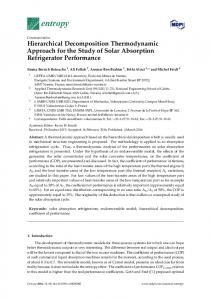
1 0 cos1 sin 1 a b cos2 sin 2 0 sin cos cos2 2 1 1 c d sin 2 The Figure 1 shows the algorithm, based on the trigonometric form (13) for calculation of matrices [C1] and [C2] by using the direct SVD of the matrix [X] of size 2×2. This algorithm is the basic building element - the kernel, used to create the HSVD algorithm. As it follows from Eq. (13), the number of needed parameters for its description is 4, i.e. - the SVD2×2 is not “over-complete”. The energy of the image [X] and each eigen image [C1], [C2], is respectively:
1 and 2 are the corresponding singular values of the symmetrical matrices [Y] and [Z];
Copyright © 2015, Infonomics Society
288
International Journal Multimedia and Image Processing (IJMIP), Volume 5, Issues 3/4, September/December 2015
2
2
E X x i2. j a 2 b 2 c 2 d 2 ,
(15)
i 1 j1 2
2
E C1 ci2, j (1) 12 i 1 j1 2
2
E C2 i 1 j1
A , 2 (16)
A ci2, j (1) 22 . 2
From the Perceval condition for energy preservation (E X E C1 E C2 ) and from Eqs. (15) and (16) it follows, that E C1 E C2 , i.e., the energy E X of the matrix [X] is concentrated mainly in the first SVD2×2 component. The concentration degree is defined by the relation:
E C1
E C1 E C2
12 12 22
1 [1 (A/ )]. 2
a [X ] c
a
(17)
b d
b
c
d
a c b d
ab cd
a b c d
ac bd
2 2
2
2
2
2
2
2
SVD 2×2 θ1 (1 /2)arctg 2 /
a2 b2 c2 d2
θ 2 (1 /2)arctg2 /
A 4 2
F1sin1
F2cos1
2 (A) / 2
F3 sin 2
F4cos 2
b1 d1 b3 d 3
a 2 c 2 a 4 c 4
b2 d 2 . (18) b4 d 4
On each sub-matrix [Xk(2)] of size 22 (k=1,2,3,4) is applied SVD2×2, in accordance with Eq. (3). As a result, it is decomposed into two components: [Xk (2)]1,k [L1,k (2)]2,k[L2,k (2)][C1,k (2)][C2,k (2)]
(19)
for k=1,2,3,4;
where 1,k (1,k A1,k ) / 2 , 2,k (2,k A 2,k ) / 2 , [L1,k (2)] U1,k V1t,k , [L 2,k (2)] U 2,k V2t,k . Using the matrices [C m ,k (2)] of size 22 for
P2 F2 F3
P3 F1F4 P4 F1F3
P P3 [C2] 2 4 P2 P1
P P [C1] 1 1 2 P3 P4
2 2 c111 1P1 c112 1P2 c121 1P3 c122 1P4 c11 2P3 c2212P2 c222 2P1 2P4 c12
c1 c1 [C1 ] 111 112 c21 c22
a 1 [X1(2)] [X 2 (2)] c1 [X(4)] [X 3(2)] [X 4 (2)] a 3 c3
2
1 (A) / 2
P1F2F4
Hence, the total energy of the matrix [X] is concentrated in the first SVD component only. The hierarchical n-level SVD (HSVD) for the image matrix [X(N)] of size 2n2n pixels (N=2n) is executed through multiple applying the SVD on the image sub-blocks (sub-matrices) of size 22, followed by rearrangement of the so calculated components. In particular, for the case, when the image matrix [X(4)] is of size 2222 (N=22=4), the number of the hierarchical levels of the HSVD is n=2. The flow graph, which represents the HSVD calculation, is shown in Figure 2. In the first level (r=1) of the HSVD, the matrix [X(4)] is divided into four sub-matrices of size 22, as shown in the left part of Fig. 3. Here the elements of the sub-matrices on which is applied the SVD2×2 in the first hierarchical level, are colored in same color (yellow, green, blue, and red). The elements of the sub-matrices are:
2 c2 c12 [C2 ] 11 2 2 c21 c22
Figure 1. The algorithm for Direct SVD of the matrix [X] of size 22 (SVD2×2)
In particular, for the case, when the matrix [X] is with equal values of the elements (a=b=c=d), from Eqs. (13), (15), (16) and (17) is obtained E X E C1 4a 2 , E C 2 0 and 1 .
Copyright © 2015, Infonomics Society
k=1,2,3,4 and m=1,2, are composed the matrices [C m (4)] of size 44: [C m,1(2)] [C m,2 (2)] [C m (4)] [C m,3(2)] [C m,4 (2)] c11(m,1) c12(m,1) c11(m,2) c (m,1) c14(m,1) c13(m,2) 13 c11(m,3) c12(m,3) c11(m,4) c13(m,3) c14(m,3) c13(m,4)
c12(m,2) (20) c14(m,2) c12(m,4) c14(m,4)
for m=1,2. Hence, the SVD decomposition of the matrix [X] in the first level is represented by two components: [X(4)] = [C1 (4)] + [C 2 (4)] ([C1,1(2)][C 2,1(2)]) ([C1,2(2)][C 2,2(2)]) ([C1,3(2)][C 2,3(2)]) ([C1,4(2)][C 2,4(2)])
(21)
In the second level (r=2) of HSVD, on each matrix [C m (4)] of size 44 is applied four times the SVD2×2. Unlike the transform in the previous level,
289
International Journal Multimedia and Image Processing (IJMIP), Volume 5, Issues 3/4, September/December 2015
in the second level the SVD2×2 is applied on the submatrices [Cm,k(2)] of size 22, whose elements are mutually interlaced and are defined in accordance with the scheme, given in the upper part of Fig. 2. The elements of the sub-matrices, on which is applied the SVD2×2 in the second hierarchical level are colored in same color (yellow, green, blue, and red). As it is seen from the Figure, the elements of the sub-matrices of size 2×2 in the second level are not neighbors, but placed one element away in
horizontal and vertical directions. In result, each matrix [C m (4)] is decomposed into two components: [Cm (4)] [Cm,1 (4)] [Cm,2 (4)] for m=1,2.
(22)
Then, the full decomposition of the matrix [X] is represented by the relation (23): 2
2
[X(4)][C1,1(4)][C1,2 (4)][C 2,1(4)][C 2,2 (4)][C m,s (4)] m 1s 1
Block SVD2x2 for level 2 11
ci (1,1) ci (1,2) c (2,1) ci (2,2) [Ci ] i ci (3,1) ci (3,2) i=1,2 ci (4,1) ci (4,2) 4x4
ci (1,3) c (2,3) i ci (3,3) c (4,3) i
ci (1,4) ci (2,4) ci (3,4) ci (4,4)
21
12
[Ci (1)] 31
22
[Ci (2)] 41
32
42
[C i ] 13
23
14
33
24
[Ci (4)]
[Ci(3)] 43
34
44
ci,s(1,1) ci.s(2,1) [Ci,s ] ci,s(3,1) i=1,2 s=1,2 ci,s(4,1) 4x4
ci,s(1,2) ci,s(2,2) ci,s(3,2) ci.s(4,2)
4x4
4x4
Level 1
Block SVD2x2 for level 1 11
12
21
[ X1 ] 13
22
23
24
32
41
42
34
43
[X ] [ X3 ] 33
x11 x [X] 21 x31 4x4 x 41
X(1,2)
c2(1,2) c1(1,2)
SVD 2x2
Rearrangement
C2(1,3)
c1(1,3)
[Ci,1] i=1,2
X(2,1)
c2(2,1) c1(2,1)
c2(3,1) c1(3,1)
X(2,2)
c2(2,2) c1(2,2)
c2(3,3) c1(3,3)
X(1,3)
c2(1,3) c1(1,3)
c2(1,2) c1(1,2)
X(1,4)
c2(1,4) c1(1,4)
c2(1,4) c1(1,4)
[C1,1]/[C1,2]/[C2,1]/[C2,2 ] C2,2(1,1) C2,1(1,1) C1,2(1,1) C1,1(1,1)
c2(1,1) c1(1,1)
SVD 2x2 SVD 2x2 SVD 2x2 [C(1)] SVD 2x2
[X 2 ] 14
31
c2(1,1) c1(1,1)
[X1] 2x2 SVD 2x2
Level 2
[ C 1 ]/[ C 2 ]
X(1,1)
ci,s(1,4) ci,s(2,4) ci,s(3,4) ci,s(4,4)
ci,s(1,3) c (2,3) i,s ci,s(3,3) c (4,3) i,s
C2,2(1,2) C2,1(1,2) C1,2(1,2) C1,1(1,2) C2,2(2,1) C2,1(2,1) C1,2(2,1) C1,1(2,1) C2,2(2,2) C2,1(2,2) C1,2(2,2) C1,1(2,2)
2x2
[Ci,s,1] i=1,2 s=1,2
[X 4 ]
x12 x 22 x32 x 42
x13 x 23 x33 x 43
44
x14 x 24 x34 x 44
[X2] 2x2
SVD 2x2
SVD 2x2
X(2,3)
c2(2,3) c1(2,3)
c2(3,2) c1(3,2)
c2(2,4) X(2,4)
c1(2,4)
c2(3,4) c1(3,4)
X(3,1)
c2(3,1) c1(3,1)
c2(2,1) c1(2,1)
c2(3,2) c1(3,2)
c2(2,3) c1(2,3)
X(3,2)
[X3] 2x2
SVD 2x2
SVD 2x2
[Ci,3] i=1,2 c2(4,1)
X(4,1)
c2(4,1) c1(4,1)
c1(4,1)
X(4,2)
c2(4,2) c1(4,2)
c2(4,3) c1(4,3)
X(3,3)
c2(3,3) c1(3,3)
c2(2,2) c1(2,2)
c2(3,4) c1(3,4)
c2(2,4) c1(2,4)
X(3,4)
SVD 2x2
[X4] 2x2 SVD 2x2
SVD 2x2 SVD 2x2 SVD 2x2 [C(1)] SVD 2x2
[Ci,2] i=1,2
[Ci,4] i=1,2
X(4,3)
c2(4,3) c1(4,3)
c2(4,2) c1(4,2)
X(4,4)
c2(4,4) c1(4,4)
c2(4,4) c1(4,4)
SVD 2x2 SVD 2x2 SVD 2x2 [C(1)] SVD 2x2
SVD 2x2 SVD 2x2 SVD 2x2 [C(1)] SVD 2x2
C2,2(1,3) C2,1(1,3) C1,2(1,3) C1,1(1,3) C2,2(1,4) C2,1(1,4) C1,2(1,4) C1,1(1,4) C2,2(2,3) C2,1(2,3) C1,2(2,3) C1,1(2,3) C2,2(2,4) C2,1(2,4) C1,2(2,4) C1,1(2,4)
C2,2(3,1) C1,1(3,1) C1,2(3,1) C1,1(3,1) C2,2(3,2) C2,1(3,2) C1,2(3,2) C1,1(3,2) C2,2(4,1) C2,1(4,1) C1,2(4,1) C1,1(4,1) C2,2(4,2) C2,1(4,2) C1,2(4,2) C1,1(4,2)
C2,2(3,3) C2,1(3,3) C1,2(3,3) C1,1(3,3) C2,2(3,4) C2,1(3,4) C1,2(3,4) C1,1(3,4) C2,2(4,3) C2,1(4,3) C1,2(4,3) C1,1(4,3)
2x2
[Ci,s,2] i=1,2 s=1,2
2x2
[Ci,s,3] i=1,2 s=1,2
2x2
[Ci,s,4] i=1,2 s=1,2
C2,2(4,4) C21(4,4) C1,2(4,4) C1,1(4,4)
Figure 2. Flow graph of the HSVD algorithm represented through the vector-radix (2×2) for a matrix of size 4×4
Hence, the decomposition for image of size 4×4 comprises four components. The matrix [X(8)] is of
Copyright © 2015, Infonomics Society
size 2323 (N=23=8 for n=3), and in this case the HSVD is executed through multiple calculation of
290
International Journal Multimedia and Image Processing (IJMIP), Volume 5, Issues 3/4, September/December 2015
the SVD2×2 on blocks of size 22, in all levels (the general number of the decomposition components is eight). In the first and second levels, the SVD2×2 is executed in accordance with the scheme, shown in Figure 1.
=2n-1×4n-1. The total number of SVD2×2 is correspondingly М=M(1+2+...+2n-1)=4n-1(2n-1)=22n-2(2n-1). Then the total number of the algebraic operations for HSVD of size 2n2n is:
In the third level, the SVD2×2 is mainly applied on sub-matrices of size 22. Their elements are defined in similar way, as shown on Fig. 1, but the elements of same color (i.e., which belong to same sub-matrix) are moved three elements away in horizontal and vertical directions. The so described HSVD algorithm could be generalized for the cases, when the image [X(2n)] is of size 2n2n pixels. Then the relation (23) becomes as shown below:
O HSVD (2 n 2 n )M O SVD (22)54 2 2 n -2 (2 n 1)
2
2
2
[X(2n )] .....[Cp1 ,p2 ,...pn (2n )] p1 1p 2 1
(24)
pn
The maximum number of the HSVD decomposition levels is n, the maximum number of the decomposition components (24) is 2n, and the distance in horizontal and vertical direction between the elements of the blocks of size 22 in the level r is correspondingly (2r-1-1) elements, for r =1,2,..,n.
4. Computational complexity of the Hierarchical 2D SVD 4.1. Computational complexity of SVD22
272 2 n -1(2 n 1).
(26)
4.3. Computational complexity of SVD of size 2n2n For the calculation of the matrices [Y(N)] and 2n 2 [Z(N)] of size NN for N=2n are needed m 2 n 1
multiplications and s 2 (2 1) additions in total. The global number of operations is: n
O Y, Z ( N)2 2n 2 2 n 1 (2 n 1)2 n 1 (3 2 n 1). (27) In accordance with [21], the number of operations O(N) for the iterative calculation of all N eigenvalues and the eigen N-component vectors of the matrix of size NN for N=2n with L iterations, is correspondingly:
O val ( N) (1/ 6)(N1)(8N 2 17 N42) (1/ 6)(2n 1)(22n 317 2n 42), (28)
The computational complexity could be defined by using the Eq. (3), and taking into account the operations multiplication and addition, needed for the preliminary calculation of the components , , , , , A , 1, 2, 1, 1, defined by the Eqs. (4)-(9). Then: - The number of the multiplications, needed for the calculation of Eq. (3) is m = 39; - The number of the additions, needed for the calculation of Eq. (3) is s =15. Then the total number of the algebraic operations executed with floating point for SVD of size 22 is:
O vec (N)N[2N(LNL1)-1]2n [2n 1(2n L L1)-1] (29) The number of the needed operations for calculation
of the eigen vectors U s and Vs in accordance with Eq. (29) should be doubled. From the analysis of Eq. (1) it follows that: - The number of needed multiplications for all 3n 1
components is: m 2 (2 2 ) 2 ; - The number of needed additions for all components n
2n
2n
is: s 2 1. Then the total number of needed operations for the calculation of Eq. (1) is: n
OSVD (2 2) m s 54. (25)
OD( N)23n 1 2n 12n (22n 11)12n (22n 11)1 (30)
4.2. Computational complexity of for HSVD of size 2n2n
Hence, the total number of algebraic operations, needed for the execution of SVD of size 2n2n is (31):
The computational complexity is defined on the basis of SVD2×2. In this case, the number М of the sub-matrices of size 22, which comprise the image of size 2n2n, is 2n-12n-1=4n-1, and the number of decomposition levels is n. - The SVD2×2 number in the first level is М1=М=4n-1; - The SVD2×2 number in the second level is М2=2×М=2×4n-1; - The SVD2×2 number in the level n is Мn=2n-1×M=
Copyright © 2015, Infonomics Society
O SVD(2n2 n ) O Y , Z (2 n )O val (2 n )2O vec (2 n )O D (2 n ) 2 2 n 1[2L(2 n 1) 2 n 15] (1 / 6)(2 2 n 3 17 2 n 42)1.
4.4. Relative computational complexity of the HSVD The relative computational complexity of the HSVD could be calculated on the basis of Eqs. (31) and (26), using the relation below:
291
International Journal Multimedia and Image Processing (IJMIP), Volume 5, Issues 3/4, September/December 2015
(n,L)
OSVD(2 n2 n )
Each tree branch has a corresponding eigen value
1 O HSVD(2 2 ) 812 2n (2 n 1) n
s,k , or resp. s,k s,k
n
32 n 1[2 n 2 (2 n L L1) 2 n 1(2 n 3)3] n (2 1)(2 2n 3 172 n 42)6 (32)
s,k (m) or resp. s,k (m) s,k (m) - for the level 2
For n=2,3,4,5 (i.e., for image blocks of size 44, 88, 1616 and 3232 pixels), the values of (n,L) for L=10 are given in Table 1. Table 1. Coefficient (n,L) of the relative reduction of the computational complexity of the HSVD towards the SVD as a function of n, for L=10
n (n,10)
2 5.94
3 4.21
4 3.67
5 3.44
For big values of n the relation (n,L) does not depend on n and trends towards:
(n, L) n 0.1 (3L1) (33) Hence, for big values of n, when the number of the iterations L 6, the relation (n, L) 1 , and the computational complexity of the HSVD is lower than that of the SVD. Practically, the value of L is significantly higher than 4. For big values of n the coefficient (n,10)=3.1 and the computational complexity of the HSVD is three times lower than that of the SVD.
5. Representation of the 2D HSVD algorithm through tree-like structure The tree-like structure of the HSVD algorithm of n=2 levels, shown in Figure 3, is built on the basis of Eq. (23), for image block of size 4×4. As it could be seen, this is a binary tree. For a block of size 8×8, this binary tree should be of 3 levels (n=3).
[X1] [X2]
[X]
[C1]
1,3 1,4
(44)
HSVD Level 1
1,1(1) 1,2(1) 1,1(2) 1,2(2) HSVD
2,1 2,2 (44)
2,3 2,4
[C2]
2,1(1) 2,2(1) 2,1(1) 2,2(1)
1,3(1) 1,4(1) 1,3(2) 1,4(2) Level 2 2,3(1) 2,4(1) 2,3(1) 2,4(1)
[C1,1] (44) [C1,2]
[C2,1] (44) [C2,2]
Figure 3. Binary tree, representing the HSVD algorithm for the image matrix [X] of size 44
Copyright © 2015, Infonomics Society
(m=1,2). The total number of the tree branches shown in Figure 4, is equal to six. It is possible some branches to be cut-off, if for them are satisfied the or conditions: s,k s,k (m) 0 s,k s,k s,k (m) s,k (m), i.e., when they are equal to 0, or are smaller than a small threshold s,k , resp. s,k (m). To cut off one НSVD
component [Ci] in a given level, it is necessary all values of i, which participate in this component, to be equal to zero, or very close to it. In result, the decomposition in the corresponding branch could be stopped before the last level n. From this follows, that the НSVD algorithm is adaptive in respect of the contents of each image block. In this sense, the algorithm НSVD is adaptive and could be easily adjusted to the requirements of each particular application.
6. Decomposition for tensor of size 222 The 3rd order tensor [T] with rank 2 and size 2×2×2, is noted here as [Т2×2×2], and is the kernel of the decomposition of the tensor [T] of size N×N×N (3rd order tensor with rank N, for N=2n). After unfolding the tensor [T2×2×2] in vertical direction, is obtained: a b e f unfold[T222 ] [X1] [X 2] c d g h (34) The HSVD algorithm for the tensor [T] of size 2×2×2, based on the SVD2×2, is shown on Fig. 4. In the first level of HSVD for the tensor [T2×2×2], on each matrix [X1] and [X2] is applied SVD2×2, and in result is got (35): a b e f [X1] [C11][C12], [X 2] [C 21][C 22] (35) c d g h
(44)
[X3] [X4]
1,1 1,2
for the level 1, and
The obtained matrices [Ci,j] of size 2×2 for i,j=1,2 should be rearranged in new couples in accordance with the decrease of their energy i2, j . After the rearrangement, the first couple of matrices [C11] and [C21], which have high energy, defines the tensor [T1(2×2×2)], and the second couple [C12] and [C22] which have lower energy - the tensor [T2(2×2×2)]. Then:
[T222 ] [T1( 222) ] [T2( 222) ]. (36) After unfolding both tensors in horizontal direction, is obtained:
292
International Journal Multimedia and Image Processing (IJMIP), Volume 5, Issues 3/4, September/December 2015
unfold [T1( 222) ] unfold [T2( 222) ]
In result of the execution of the two levels of HSVD2×2×2, the tensor [Т2×2×2] is represented as below:
(37) In the second level of HSVD, on each matrix [Xi,j] of size 2×2, in Eq. (37) is applied SVD2×2 and in result:
[T222][T1( 222) (1)][T1( 222)(2)][T2( 222)(1)][T2( 222)(2)]
[X11]
[X 21] [X12] [X 22]
2
2
[Ti ( 222) ( j)].
(40)
i 1 j1
[X11 ] [C111 ] [C112 ], [X 21 ] [C211 ] [C212 ],
Here the tensors [Ti(2×2×2)(j)] of size 2×2×2 are arranged in accordance with the decrease of the singular values I,j,k of the matrices [Ci,j,k]. The flow graph of the 2-level HSVD algorithm for the tensor [T] of size 2×2×2, is shown on Fig. 5. From Eq. (25) it follows, that the total number of the algebraic operations for HSVD with tensor [T2×2×2] is:
[X12 ] [C121 ] [C122 ], [X 22 ] [C221 ] [C222 ]. (38) The obtained matrices [Ci,j,k] of size 2×2 for i,j,k=1,2 are rearranged into 4 new couples with similar energy i2, j,k in order, defined by its decrease. Each of these
4 couples of matrices defines a corresponding tensor of size 2×2×2. After their unfolding is obtained (39):
OHSVD(222)=6OSVD(22)=654=324. (41)
inf old{[T1(222)(1)][T1(222) (2)][T2(222) (1)][T2(222) (2)]}
[C111]
[C211][C121] [C221][C112] [C212][C122] [C222].
e
HSVD2x2x2
f
[T222 ] SVD2x2 a
b
SVD2x2 g [X1]
[T222 ] [T1] [T2 ] [T1(1)] [T1(2)] [T2 (1)] [T2 (2)]
[X2] h
c
[X2] e f [C21] [C22] g h [X1] a b [C11] [C12] c d
d
Rearrengement 1 a b [X11] 11 12 c13 d1411
13
23
Level 1
SVD2x2 [C21]
[C11]
e f [X12] 15 16 g17 h1815
14
12
21
+
[T2 ]
Level 2
[C121] +
26
f e [X22] 25 26 g h 27 28
[C222]
[C212]
[C112]
[T1 (2)]
a b [X21] 21 22 c23 d24
Rearrengement 2
Rearrengement 2
[T1(1)]
28
SVD2x2
25
16
[C221]
22
27
18
[ T1 ]
SVD2x2
[C111]
[C22]
[C12]
17
[C211]
24
SVD2x2
+
[T2 (1)]
[C122] +
[T2(2)]
Figure 4. HSVD algorithm for the tensor [T] of size 2×2×2, based on the SVD2×2, and binary 2-level tree
Copyright © 2015, Infonomics Society
293
International Journal Multimedia and Image Processing (IJMIP), Volume 5, Issues 3/4, September/December 2015
[X11]
a b [X1 ] [C11] [C12 ], c d Level 1
a
b
Tensor
[X1]
[T222 ] e [X2] a b g
SVD SVD2x2 2x2 1
g
c21(2,1) c21(1,1) c21(2,2) c21(1,2)
[X11]
d
c12(2,2) c11(2,2)
[C212] [C211]
[C112] [C111]
[C21]
c12(2,1) c12(1,1)
c22(1,2) c21(1,2)
c12(2,2) c12(1,2)
f h
g
c22(2,1) c21(2,1)
c22(2,1) c22(1,1)
h
c22(2,2) c21(2,2)
c22(2,2) c22(1,2)
f [X2]
SVD SVD2x2 2x2 2
[X12]
[C121]
[C211] [C111]
C212(1,2) C211(1,2) C112(1,2) C111(1,2) C212(2,1) C211(2,1) C112(2,1) C111(2,1)
[C222]
c22(1,1) c21(1,1)
[C221] [C122 ] C222(1,1) [C121] C221(1,1)
[X22]
[C112]
C222(1,2) C221(1,2) C122(1,2) C121(1,2)
e f [X2] [C21] [C22]. g h
[ T2 ] [X22]
[X12] [C121] [C122], [X22] [C221] [C222].
C122(1,1) C212(1,1) C112(1,1) C222(1,2) C122(1,2) C212(1,2) C112(1,2) C222(2,1) C122(2,1) C212(2,1) C112(2,1) C222(2,2) C122(2,2) C212(2,2)
C222(2,1) C221(2,1) C122(2,1) C121(2,1) C222(2,2) C221(2,2) C122(2,2)
C112(2,2)
C121(2,2) [X12]
C221(1,1) C121(1,1) C211(1,1) C111(1,1) C221(1,2) C121(1,2) C211(1,2) C111(1,2) C221(2,1) C121(2,1) C211(2,1) C111(2,1) C221(2,2) C121(2,2) C211(2,2) C111(2,2)
[C222] [C122] [C212] C222(1,1)
C122(1,1) C121(1,1)
SVD 2x2 SVD 2x2 SVD 2x2 SVD 2x2 [C(1)] 5/6
[ T12 ]
[ T11 ]
C212(2,2) C211(2,2) C112(2,2) C111(2,2)
[C22 ]
[C121]
Rearrangement 2 [C221]
C212(1,1) C211(1,1) C112(1,1) C111(1,1)
SVD 2x2 SVD 2x2 SVD 2x2 SVD 2x2 [C(1)] 3/4
[C221]
[C211] [C111]
[X21] [C211] [C212],
[X21]
[X1 ] [X 2 ] d
c11(2,2) c11(1,2)
h
unfold [T222 ]
e
c12(1,2) c11(1,2)
c
e
b
c11(2,1) c11(1,1)
c12(2,1) c11(2,1)
[X11] [C111] [C112],
Level 2
c12(1,1) c11(1,1)
f
c [X1] d
a c
[X21]
Rearrangement 1
[C12 ]
[C11]
[ T1 ]
[C212] [C112]
[ T21 ]
[C222] [C122]
[T22 ]
Figure 5. The flow graph of the 2-level HSVD for the tensor [T] of size 2×2×2, based on the SVD2×2
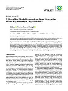
7. The 3D HSVD algorithm for image of size 444 In this case, the tensor [Т444] (for N=4) is divided into 8 sub-tensors [T2×2×2], as shown on Fig. 5. The pixels, which belong to one kernel, are colored in same color: yellow, red, green, blue, white, purple, light blue, and orange. The HSVD444 algorithm is executed in two levels. In the first level of
HSVD444, on each kernel [T2×2×2(i)], where i=1,2,..,8, from the tensor [Т444], is applied the HSVD222 algorithm, shown on Fig. 6. As a result, each kernel is represented as a sum of four components: [T222 (i)][Ti,1 (1)][Ti,1 (2)][Ti,2 (1)][Ti,2 (2)] (42)
for i=1,2,..,8. The decomposition of all kernels leads to the representation of the tensor [Т444] as a sum of four components as well:
Tensor 4 4×4×4 Tensor 3 4×4×4
[T444 ] Tensor 2 4×4×4
2
(43)
i 1 j1
Tensor 1 4×4×4
Sub-tensor (kernel) 2×2×2
Figure 6. Division of tensors [Тi(4×4×4)(j)] into the kernels [Tj(2×2×2)(i)] in the second HSVD444 level, where the HSVD222 is applied on each group of pixels of same color (32 in total)
Copyright © 2015, Infonomics Society
2
[Ti(444) ( j)] .
Each of the four tensors [Тi(4×4×4)(j)] consists of eight kernels [Ti,k(2×2×2)(j)] for i=1,2, k=1,2, j=1,2, and hence the total number of kernels is 32. The tensors [Тi(4×4×4)(j)] in Eq. (43) are rearranged in accordance with the energy decrease of the kernels [Ti,k(2×2×2)(j)], which build them. In the second level of HSVD444, each of the four tensors [Тi(4×4×4)(j)] from Eq. (42), is divided into 8 sub-tensors (kernels) [Ti,k(2×2×2)(j)] for i=1,2, j=1,2 and k=1,2 in the way, defined by the spatial set of pixels of same color, shown on Fig. 6. The color of the pixels for each kernel corresponds to that of the first level of the HSVD444 algorithm: yellow, red, green, blue, white, purple, light blue, and orange.
294
International Journal Multimedia and Image Processing (IJMIP), Volume 5, Issues 3/4, September/December 2015
On each kernel is applied again the two-level НSVD2×2×2 in accordance with Figure 4. After the execution of the second decomposition level, the tensor [Т444] is represented as a sum of 16 components: 4
(44)
i 1 j1
The so obtained 16 tensors [Тi(4×4×4)(j)] are arranged in accordance with the decreasing values of the singular values (energies) of the kernels, [Ti,k(2×2×2)(j)], which compose them, for i=1,2, j=1,2 and k=1,2. In case that the HSVD444 is represented through the calculation graph from Fig. 5, the total number of decomposition levels is four. The corresponding binary tree structure of 16 leaves is shown in Figure 7. As it could be seen from Figures 5, 6 and 7, in the first level of HSVD444 the decomposition HSVD222 is applied eight times, and in the second level - 32 times.
Truncated 3D HSVD
Tensor 4×4×4
Rejected component
Rearrangement Retained component
Level 1
Rearrangement Level 1 of 3D HSVD
Level 2
Rearrangement
Level 3
Rearrangement 1
2
3
Level 2 of 3D HSVD
is represented as a sum of N2=22n eigen tensors: [T2 n 2 n 2 n ]
4
[Ti(444) ( j)] .
[T444 ]
(2×2) HSVDN×N×N algorithm, the tensor [T2n 2n 2n ]
4
5
6
7
Tensor approximation
8
9
10
11
12
13
14
15
16
Level 4
Figure 7. Structure of the calculation graph for HSVD444: full binary tree of 4 levels and 16 leaves
Then, taking into account Eq. (41), for the total number of algebraic operations for HSVD444 of the tensor [T4×4×4], is obtained (45):
O HSVD (222222) 8(1 4) OHSVD (222) 40 324. As an example (Fig.7) the decomposition elements (tensors of size 444), which could be reduced through threshold selection (if this condition is satisfied for the second component in the first level of HSVD444), are colored in blue.
8. 3D HSVD for tensor-represented image of size N×N×N
2n 2n
[Ti(2 2 2 ) ( j)]. n
n
n
(46)
i 1 j 1
The eigen tensors [Ti ( 2 n 2 n 2 n ) ( j)] of size 2n×2n×2n for i, j, k = 1,2,..,2n are arranged in accordance with the decreasing values of the kernels energies [Ti,k(2×2×2)(j)], which build them. The computational complexity of the algorithm for decomposition of the tensor [T2n 2n 2n ] could be defined, taking into account that for the execution of HSVD 2 n 2 n 2 n are needed n levels, where the HSVD222 is applied on each level. Then, from Eqs. (41) and (45) follows: n 1
O HSVD (2 n2 n2 n ) 4 n 2 8(1 4i )O HSVD(222) (8 / 3)(4 1)4 n
n 2
i 1 2n
324 54(2 - 1)22n.
(47)
In the relation above, 54 represents the number of algebraic operations for SVD22, which is applied ( N 2 - 1)N 2 times on the tensor [TN×N×N]. The SVD22 is the basic operation of the decomposition, which is executed repeatedly, the new algorithm is called radix-(2×2) HSVD. In accordance to Grasedyck [27], the complexity to compute hierarchical SVD for HTucker tensors of rank 2n, mode size 2n and order 3, is О(3×23n+3×24n). The comparison of the computational complexity of O(24n) and the HSVD 2 n2 n2 n shows the advantage of the last one. The
relative
computational
complexity
of
HSVD 2 n 2 n 2 n for a 3D image is: (n)
O HTucker (2 n2 n 2 n ) 3(23n 2 4n ) 3(12 n )3 (48) O HSVD (2 n 2 n 2 n ) 2 4n
In case that the number of decomposition components from Eq. (46) is limited through threshold selection of the low-energy components, the computational complexity could be additionally reduced, which follows from Eq. (47). Besides, the mean square approximation error of the tensor [TN×N×N], got in result of the components reduction, is minimum. This follows from the fact, that each kernel is defined through HSVD222 on the basis of the "classic" SVD22, which minimizes the mean square approximation error.
9. Conclusions The decomposition of the tensor [Т444] in correspondence with Eq. (44) could be generalized for the case, when the tensor [TN×N×N] is of size N×N×N for N=2n. As a result of the use of the radix-
Copyright © 2015, Infonomics Society
In respect of the famous H-Tucker decomposition, the presented 3DHSVD algorithm is quasi-optimal. The basic difference from the Tucker algorithm is, that each decomposition component for
295
International Journal Multimedia and Image Processing (IJMIP), Volume 5, Issues 3/4, September/December 2015
a tensor of size N×N×N is represented as an outer product of 3 mutually orthogonal N-dimensional vectors, while for the 3DHSVD the component is defined by the kernels of size 2×2×2, contained by it. The basic advantages of the new decomposition for multi-dimensional images are the low computational complexity and the tree-like structure, which permits cutting-off the low-energy branches through threshold selection. This makes the algorithm suitable for parallel processing with multi-processor systems, where the basic processor executes the kernel decomposition algorithm for a tensor of size 2×2×2. The 3DHSVD algorithm opens new possibilities for fast image processing in various application areas, such as: image filtration, segmentation, merging, digital watermarking, extraction reduced number of features for pattern recognition, etc.
[11] Aharon, M., Elad, M., Bruckstein, A. (2006). The KSVD: an algorithm for designing of overcomplete dictionaries for sparse representation, IEEE Trans. on Signal Processing, 54, pp. 4311-4322. [12] Singh, S., Kumar, S. (2011). SVD Based Sub-band Decomposition and Multiresolution Representation of Digital Colour Images, Pertanika J. of Science & Technology, 19 (2), pp. 229-235. [13] Kountchev, R., Kountcheva, R. (2015). Hierarchical SVD for Halftone Images. The 7th International Conference on Information Technology Big Data, Al Zayatoonah University, Amman, Jordan, May 12-15, pp. 50-58. [14] Kountchev, R., Kountcheva, R. (2015). Hierarchical SVD-based Image Decomposition with Tree Structure, Intern. J. of Reasoning-Based Intelligent Systems, 7(1/2),pp.114-129.
References
[15] De Lathauwer, L. (2008). Decompositions of a higher-order tensor in block terms - Part I and II, SIAM J. Matrix Anal. Appl., Vol. 30, pp. 1022-1066.
[1] Fieguth, P. (2011). Statistical image processing and multidimensional modeling, Springer.
[16] Kolda, T., Bader, B. (2009). Tensor decompositions and applications, SIAM Review, 51(3), pp. 455-500.
[2] Diamantaras, K., Kung, S. (1996). Principal Component Neural Networks, Wiley, New York.
[17] Bergqvist, G., Larsson, E. (2010). The Higher-Order SVD: Theory and an Application, IEEE Signal Processing Magazine, 27(3), pp. 151-154.
[3] Orfanidis, S. (2007). SVD, PCA, KLT, CCA, and All That, Rutgers University Electrical & Computer Engineering Department, Optimum Signal Processing, pp. 1-77.
[18] Salmi, J., Richter, A., Koivunen, V. (2009). Sequential Unfolding SVD for Tensors with Applications in Array Signal Processing, IEEE Trans, on Signal Processing, 57 (12), pp. 4719-4733.
[4] Levy, A., Lindenbaum, M. (2000). Sequential Karhunen-Loeve Basis Extraction and its Application to Images, IEEE Trans. on Image Processing, Vol. 9, No. 8, pp. 1371-1374.
[19] Grasedyck, L. (2010). Hierarchical SVD of Tensors, SIAM J, on Matrix Analysis and Applications, 31(4), pp. 2029-2054.
[5] Sadek, R. (2012). SVD Based Image Processing Applications: State of The Art, Intern. J. of Advanced Computer Science and Applications, 3(7), pp. 26-34.
[20] Oseledets, I. (2011). Tensor-train decomposition, SIAM Journal on Scientic Computing, 33(5), pp. 22952317.
[6] Drinea, E., Randomized SVD Proc. of the 8th Manolopoulos, S. 278-288.
Drineas P., Huggins, P. (2001). A Algorithm for Image Processing Appl., Panhellenic Conf. on Informatics, Y. Evripidou (Eds), Nicosia, Cyprus, pp.
[21] Cichocki, A., Mandic, D., Phan, A-H., Caiafa, C., G. Zhou, Zhao, Q., De Lathauwer, L. (2015). Tensor Decompositions for Signal Processing Applications, IEEE Signal Processing Magazine, 32(2), pp. 145-163.
[7] Holmes, M., Gray, A., Isbell, C. (2008). QUIC-SVD: Fast SVD using Cosine trees, Proc. of NIPS, pp. 673-680.
[22] Wu, Q., Xia, T., Yu, Y. (2007). Hierarchical Tensor Approximation of Multidimensional Images, IEEE Intern. Conf. on Image Processing (ICIP’07), San Antonio, TX, Vol. 6, pp. IV-49, IV-52.
[8] Foster, B., Mahadevan, S., Wang, R. (2012). A GPUbased Approximate SVD Algorithm, 9th Intern. Conf. on Parallel Processing and Applied Mathematics, 2011, LNCS, Vol. 7203, pp. 569-578. [9] Yoshikawa, M., Gong, Y., Ashino, R., Vaillancourt, R. (2005). Case study on SVD multiresolution analysis, CRM-3179, pp. 1-18. [10] Waldemar, P., Ramstad, T. (1997). Hybrid KLT-SVD image compression, IEEE Intern. Conf. on Acoustics, Speech, and Signal Processing, IEEE Comput. Soc. Press, Los Alamitos, pp. 2713-2716.
Copyright © 2015, Infonomics Society
296