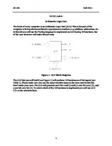
arithmetic logic unit , four bit shifter and carry save in multiplier circuits. The advantage of this type of ALU is to construct functional unit all around the input lines ...
Dr. E.N.Ganesh / (IJCSE) International Journal on Computer Science and Engineering Vol. 02, No. 05, 2010, 1824-1829
Implementation and simulation of arithmetic logic unit, shifter and Multiplier in Quantum cellular automata technology. Dr.E.N.Ganesh Professor / ECE Dept Rajalakshmi Engineering College, Thandalam, Chennai
Quantum cellular automata (QCA) is a new technology in the nanometer scale and has been considered as one of the alternative to CMOS technology. QCA have a large potential in the development of circuits with high space density and low heat dissipation and allow the development of faster computers with lower power consumption. This paper discusses the design and construction of simple two bit arithmetic logic unit , four bit shifter and carry save in multiplier circuits. The advantage of this type of ALU is to construct functional unit all around the input lines and thereby reducing circuit complexity. Four bit shifter are constructed using serial AND and OR QCA circuits. QCA multiplier designed and constructed here has advantage of carry save in by delaying one clock cycle and no of bits can also be increased by adding the full adder stages. These circuits are the building block of nanoprocessors and provide us to understand the nanodevices of the future.
1. Introduction The Quantum cellular automata (QCA) has been one of the promising nanotechnology and proposed as an alternative to CMOS technology. The analysis and simulation of the QCA circuits has many challenges. QCA circuit simulation involves larger computational complexity. Quantum dots are nanostructures created from standard semi conductive materials. These structures are modeled as quantum wells. They exhibit energy effects even at distances several hundred times larger than the material system lattice constant. A dot can be visualized as well. Once electrons are trapped inside the dot, it requires higher energy for electron to escape. Quantum dot cellular automata is an Novel technology that attempts to create general computational functionality at the nanoscale by controlling the position of single electrons [1][2][8]. The fundamental unit of QCA is QCA cell created with four quantum Dots positioned at the vertices of a square.[1] [8]. The electrons are quantum mechanical particles, they are able to tunnel between the dots in a cell. The electrons in the cell that are placed adjacent to each other will interact; as a result the polarization of one cell will be directly affected by the polarization of its neighboring cells. Fig 1 below shows quantum cells with electrons occupying opposite vertices.
1(a)
1(b)
Fig 1 shows QCA cells with four quantum dots.1 (a) P = +1 (Binary 1) 1(b) P = -1 (Binary0) [1][2][4][8]
This interaction forces between the neighboring cells able to synchronize their polarization. Therefore an array of QCA cells acts as wire and is able to transmit information from one end to another [5][6]. Thus the information is coded in terms of polarization of cell. Polarization of each cell depends on polarization of its neighboring cells. To perform logic computing, we require universally a complete logic set. We need a set of Boolean logic gates that can perform AND, OR, NOT and FANIN and FAN OUT [3] Operations. The combination of these is considered as universal because any general Boolean function can be implemented with the combination of these logic primitives. The fundamental method for computing is majority gate or majority voter method [1] [4]. Suppose three inputs are given to QCA circuit, then the output of the QCA structure is tabulated in table 1. Table 1 Majority voting scheme [4] [5]
INPUT
000 001 010 011 100 101 110 111
OUTPUT MAJORITY VOTING 0 0 0 1 0 1 1 1
The majority gate produces an output that reflects the majority of the inputs. The majority function
ISSN : 0975-3397
1824
Dr. E.N.Ganesh / (IJCSE) International Journal on Computer Science and Engineering Vol. 02, No. 05, 2010, 1824-1829 is a part of a larger group of functions called threshold functions. Threshold functions works according to inputs that reaches certain threshold before output is asserted. The majority function is most fundamental logic gate in QCA circuits. In order to create an AND gate we simply fix one of the majority gate input to 0 (P = -1). To create OR gate we fix one of inputs to 1 P = +1. The inverter or NOT gate is also simple to implement using QCA. If we place two cells at 45 degrees with respect to each other such that they interact inversely.
A
B
Control
Y
Input
Fig 2.Majority AND gate [6] [11] Control input is -1. The output of majority AND gate reflects the majority of the inputs. Suppose input A =1, B = 1, Control input 0(1), the output is equal to 1.
A
Control Input
B
Y
Fig 3 Majority OR gate [6][11][12]
Figure 2 and 3 shows the majority AND and OR gate structure. Control input to AND gate is -1 and for OR gate is +1.
Figure 4 shows clocking scheme of QCA circuits [4][5]
ISSN : 0975-3397
II. QCA CLOCKING Clocking is the requirement for synchronization of information flow in QCA circuits. It requires a clock not only to synchronize and control information flow but clock actually provides power to run the circuit [9] [10] [11]. The cells are not powered from any other external source apart from the clock. These clocks have been proposed to control the potential barriers between the dots. When the clock signal is high the potential barriers between the dots are low and electrons effectively spread out in the cell and no net polarization exists. As the clock signal is switched low, the potential barriers between the dots are raised high and the electrons are localized such that a polarization is developed based on the interaction of their neighbors [7][12].In short when clock is high cell is unlatched and when clock is low cell is latched. In order to pump information down a circuit in a controllable manner four clocking zones are available as shown in Figure 4. Each of clocking signal lagging in phase by 90 degrees with respect to one before. In this way, the cells are latched in series and propagate information in the same direction. So clocking is essential for QCA circuits. Here we have designed arithmetic logic unit, QCA shifter and QCA carry save multiplier using QCA designer tool [6] [14]. The design parameters are given in table2. There are two types of simulation engine used to simulate QCA circuits, bistable and coherence vector simulation. We have used coherence vector simulation to simulate QCA circuits. The coherence vector simulation is based on a density matrix approach. It can model dissipative effects as well as perform a time-dependent simulation of the design as shown in [6]. As with the other simulation engines, it assumes that each cell is a simple two-state system. For this two-state system the Hamiltonian equation can be used to study QCA circuits. Table 2 Design parameters to simulate QCA circuits using QCADesigner tool.
S.NO PARAMETERS SIMULATION 1 No of samples taken
FOR VALUE 12,800
2
Method for simulation
3
Radius of effect
Bi-stable approximation 65 nm
4
Relative permittivity
12.9
5
Clock High
9.8 x 10⁻²³
6
Clock Low
3.8 x 10⁻²²
7
Clock amplitude factor
2
8
Layer separation
11.5nm
9
Maximum separation per 100 sample Temperature at which 7K simulation performed
10
1825
Dr. E.N.Ganesh / (IJCSE) International Journal on Computer Science and Engineering Vol. 02, No. 05, 2010, 1824-1829 III. Quantum Cellular Automata Arithmetic logic unit
constructing the functional circuits on both side of the input line. This reduces error occurrence due to the interference of near by cell. A. Logical equations
Y = a + b - OR
(1)
Y = m (a, b, +1) – QCA OR
(2)
Y = (a*b)
- AND
(3)
Y = m (a, b,-1) Y = (a*b)’
QCA AND - NAND
(4) (5)
Y = m (a’, b’,-1) - QCA NAND Y = (a + b)’
(6)
- NOR
Y = m (a’, b’, +1) - QCA NOR Y=a+1
(7) (8)
- Increment
(9)
Y=a
at clock 0 (Second cycle of clock zones) (10) Y = a* b’+ a’*b - Sum (11)
Figure 5 Quantum Cellular Automata Arithmetic and Logic circuit
QCA Arithmetic logic unit is constructed using QCA designer tool as shown in figure 5. Four clocking zones are used to propagate information from input to output. Inputs a and b are available at clock 0, adder and subtractor are constructed to the left side of the input lines and other functions are constructed at the right side. Outputs sum, difference, carry and borrow are available at clock 3, similarly increment, decrement, inversion, logic outputs are also available at clock 3. Clock 1 and 2 is used to carry information to the majority gate. Two bit adder and subtractor is evaluated using the equation by majority logic method as shown by the set of equations from 1 to 18 and as per the equations the outputs for QCA ALU are evaluated. The advantage of input QCA is the availability of inverted inputs along with the input lines, so it is easy to compute for any Boolean and arithmetic expressions. QCA ALU is designed according to design parameters given in table 2 . No of cells used for simulation is 494, area for construction 0.92 micrometer2, and time for simulation is 19 seconds (nanoseconds – Since it is nanotechnology it is assumed in simulation as 1 second = 1 nanosecond). The advantage of this construction is
Y = m( m(a,b’,-1), m(a’,b,-1),+1) - QCA Sum
(12)
Y = (a*b)
- Carry
(13)
Y = m (a, b,-1)
- QCA Carry
(14)
Y = a b’+ a’*b- Borrow
(15)
Y = m (m (a, b’,-1), m (a’, b,-1), +1) - QCA Borrow
(16)
Y = a’*b – Difference
(17)
Y = m (a’, b,-1) - QCA Difference (18)
Simulated waveforms are shown in figure 6. Hence two bit QCA ALU performs same as that of digital ALU, QCA ALU plays important role in designing QCA CPU and microprocessor.
functional circuits can be built on either side of the input lines. Since the availability of both the input and its inversion are available simultaneously, flexible manner of
ISSN : 0975-3397
1826
Dr. E.N.Ganesh / (IJCSE) International Journal on Computer Science and Engineering Vol. 02, No. 05, 2010, 1824-1829
Figure 6 Simulated waveform of QCA ALU
IV. Quantum Cellular Automata Shifter QCA shifter is constructed using OR and AND serial bit arrays. OR serial bit array is made up of OR majority gate in serial mode and AND serial bit array is made up of AND majority gate in serial mode. Serial AND and OR gates are used to construct four bit QCA shifter. Figure 7 shows QCA serial OR array and figure 8 shows Four bit QCA shifter. The output of OR bit serial array has OR logic of inputs (a0,a1,a2,a3) and controlled input( +1). The advantage of this design i.e construction of shifter is by serial OR and AND array QCA cells.
Figure 7 Quantum cellular automata AND serial Array
Figure 8 Four bit Quantum cellular automata serial shifter
QCA Shifter has four inputs in0 to in3. Clocking zones are allotted for QCA wire in order to carry the
ISSN : 0975-3397
1827
Dr. E.N.Ganesh / (IJCSE) International Journal on Computer Science and Engineering Vol. 02, No. 05, 2010, 1824-1829 information. At clock 0 input in0 is available, clock 1 is allotted for in1, in2 is available at clock 2 and in3 is at clock 3. Select line is used to select the horizontal (output) line by evaluating majority logic with input and controlled input (1) as shown in figure 8. If control input is high for horizontal (out 3) line and select line is low, in0 is selected and routed to out3 by majority logic, similarly other output lines are selected and inputs are shifted accordingly. Figure 9 shows the simulated waveform of QCA shifter. Clock zones allotted in sequence for horizontal output lines and vertical input lines. Outputs Out0, out1,out2 and out3 are available at clock 0 simultaneously, QCA shifter acts as parallel in parallel out shift register. QCA shifter is designed according to table 2 , and simulation engine used here is coherence vector engine, no of cells used for simulation is 260, area used for construction is 0.5 X 0.4 micro meter2, time required for simuilation is 18 seconds (nanoseconds).
Figure 9 simulated waveform of Quantum Cellular Automata shifter
ISSN : 0975-3397
V. Quantum Cellular Automata Multiplier
Figure 10 Multiplication in Four bit QCA multiplier
We have constructed here four bit QCA multiplier, Four bit multiplication can be performed as in figure 10. QCA implementation of this multiplication is done using bit serial adders (full adders) as in [2]. The bit-serial adder is similar to the full adder except that the carry-in and carryout are connected internally with a one clock delay. Using these adders, 4 bit carry save multiplier designs are implemented. Multipliers for larger word sizes can be implemented easily by adding additional bit slices in this design. With QCADesigner the circuit functionality is verified. The following parameters are used for for coherence vector simulation, cell size = 20nm, number of samples = 102400, convergence tolerance = 0.00001, radius of effect. = 41nm, relative permittivity = 12.9, clock high = 9.8e- 22 J, clock low = 3.8e-23 J, clock amplitude factor = 2, layer separation = 11.5nm, maximum iterations per sample = 10000. 4 bit multiplier simulation results are provided with the input and output waveforms as shown in Figure 12. First and last input/output pairs are highlighted. For an N bit case, multiplier inputs are an N + 1 bit number (1 bit serial input and N bit parallel inputs) and output is a 1 bit number (serial output) ignoring a constant carry-in. The serial input and output use the order from LSB to MSB and parallel inputs are repeated whenever a new serial input is available (N cycles). For the initialization of the multiplier, N +1 zero bits at each cycle are provided for the period of N clock cycles and padding N +1 zero bits at each cycle are also provided between the input sets for the Period of N clock cycles. Completion time for one N bit multiplication takes 2N cycles. The no of cells used to construct multiplier is 507 cells, and area required to construct is 1 X 0.61 micro meter2, time for simulation in bistable approximation is 48 sec (nanoseconds). The multiplier design presented here has advantage of carry save in and propagated to the next serial adder circuit, which can be utilized to add no of bits (Adders) serially. Thus we have constructed and simulated simple QCA multiplier which is building block of nano – processor
1828
Dr. E.N.Ganesh / (IJCSE) International Journal on Computer Science and Engineering Vol. 02, No. 05, 2010, 1824-1829
Figure 11 Four bit QCA multiplier
[2] K.Walus, Wei Wang and Julliaen et al, “Quantum Cellular Automata adders” in Proc IEEE Nanotechnology conf, vol 3 page461463December 2004. [3] K.Walus, Schulaf and Julliaen et al, “High level Exploration of Quantum Dot Automata” in Proc IEEE Nanotechnology conf, vol 2,page 30- 33 2004 [4] K.Walus, Schulaf and Julliaen et al, “Circuit design based on majority gates for application with Quantum dot cellular automata” in Proc IEEE Nanotechnology conf, vol 4,page 1350- 1354, 2004. [5] K.Walus, Dimitrov and Julliaen et al, “Computer Architecture structure for Quantum Cellular Automata”in Proc IEEE Nanotechnology conf, vol 3,page 1435 – 1439 2003 [6] K.Walus, Dysart and Julliaen et al, “QCQ Designer A Rapid design and simulation tool for quantuim dot cellular automata” in IEEE transactions on Nanotechnology conf, vol 3,No – 2 June 2004. [7] K.Walus, Dysart and Julliaen et al, “Split current Quantum dot cellular automata modeling and simulation ” in IEEE transactions on Nanotechnology conf, vol 3 March 2004. [8] A. Vetteth et al., “Quantum dot cellular automata carry-look-ahead adder and barrel shifter,” in Proc. IEEE Emerging Telecommunications Tech-nologies Conf., 2002. [9] C. Lent and P. Tougaw, “A device architecture for computing with quantum dots,” in Proceeding of the IEEE, vol. 85-4, pp. 541–557, April 1997. [10]. Orlov, R. Kummamuru, R. Ramasubramaniam, C. Lent, G. Bernstein, and G. nider, “Clocked quantum-dot cellular automata shift register,” Surface Science, vol. 532, pp. 1193–1198, 2003. [11] C. Lent, B. Isaksen, and M. Lieberman, “Molecular quantum-dot cellular automata,” Journal of American Chemical Society, vol. 125, pp. 1056–1063 -2003. [12] J. Timler and C. Lent, “Maxwell’s demon and quantum-dot cellular automata,” Journal of Applied Physics, vol. 94, pp. 1050–1060, July 2003. [13] J.Timler and C.Lent “Quantum Computing with Quantum-dot Cellular Automata using Coherence Vector Formalism “ IEEE nano conference 1998 pp 4361 – 67. [14] www.qcadesigner.ca / qcatutorials.
Figure 12 Simulated waveform of Quantum cellular Automata Carry save Multiplier
VI. Conclusion We have designed and constructed Quantum cellular automata circuits like arithmetic logic unit, shifter and multiplier. It can be verified that these circuits are similar in functioning digital logic circuits and can be one of the alternative to CMOS technology. Two bit arithmetic logic unit is designed in a flexible manner such that functional circuits can be constructed on either side of the input lines, thereby reducing the polarization errors due to neighboring QCA cells. QCA shifters are designed using QCA serial arrays and four bit QCA shifter waveforms are shown. QCA shifter acts as Parallel in and parallel out shift register. Finally QCA carry save in Multiplier is constructed and verified using QCAdesinger tool. These circuits are used to construct nano-processor with high speed and low power dissipation. Reference [1].K.Walus, Wei Wang and Julliaen et al, “Majority logic reduction for Quantum Cellular Automata” in Proc IEEE Nanotechnology conf, vol 3 December 2004.
ISSN : 0975-3397
1829