3rd International Symposium on Electrical Engineering and Energy Converters
September 24-25, 2009, Suceava
Indirect Vector Control of an Induction Motor with Fuzzy-Logic based Speed Controller Iulian BIROU*, Virgil MAIER**, Sorin PAVEL**, Calin RUSU* *Department of Electrical Drives and Robots Technical University of Cluj-Napoca C. Daicoviciu Str. 15, RO-400020 Cluj-Napoca
[email protected] **Department of Industrial Power Systems Technical University of Cluj-Napoca C. Daicoviciu Str. 15, RO-400020 Cluj-Napoca
Abstract— The aim of this paper is to present a new speed control structure for induction motors (IM) by using fuzzylogic based speed controllers. A fuzzy controller is designed to achieve fast dynamic response and robustness for low and high speeds. Different types of membership functions of the linguistic variables and output/input characteristics are analyzed. A simple, but robust structure enables a wide range speed control of the driving system. The rotor flux field oriented control (FOC) is realized by using a flux observer based on the IM model with nonlinear parameters. The control is extended to operate also in the field weakening region with an optimal rotor flux regulation. The control structure was implemented on a computer system, based on a fixed point digital signal processor (DSP). To verify the performances of the proposed driving system, simulated and experimental results are presented. Index Terms— DSP-based computing system, field oriented control, fuzzy speed control, indirect vector control of induction machine.
I.
INTRODUCTION
In most of industrial drive control applications, the standard method to control induction squirrel cage motors is based on the field-oriented principle in order to achieve the best dynamic behavior [1], [2]. In the indirect vector control method, the synthesis of unit vectors does not depend on the machine terminal conditions and therefore distortion problems do not exist [3]. This allows designing a simple and more robust control structure. The disadvantage consist in the need of integrate the flux rotating frequency, to obtain the flux position. Therefore initial flux position has to be considered. Fuzzy-logic based speed controllers improve the robustness and reduce the on-line computation time of the controlled structures [4]. The off-line designing and tuning process of the controller is more complex and requires more experience and simulations than for PI or adaptive speed controllers. The requirements of a performant digital control application are a flexible control structure, reduced hardware configuration and a good dynamic behavior of the controlled process. The last two aspects can be realized by finding a compromise between the reducing of the control cycle times and the increasing of controller complexity. For industrial applications the hardware costs are also important.
That’s why a fixed-point processor based hardware can solve the problem with a good performance/cost ratio. II.
INDIRECT VECTOR CONTROL OF THE INDUCTION MOTOR
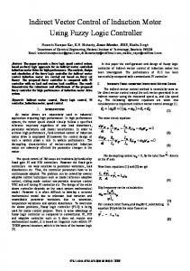
The field-orientation principle was used to control the induction motor drive system. Fig. 1 shows the structure of the indirect vector controlled IM, fed by an adaptive current controlled PWM voltage fed converter [5]. The field orientation was made according to the rotor flux vector. The magnitude of the rotor flux is obtained using a flux observer, but the frequency of the rotor field is neither computed nor estimated; it is imposed depending on the load torque value i.e. the slip frequency, and then integrated to obtain the imposed rotor flux position (angle λr). For speeds over the nominal value a field-weakening block is used to obtain the imposed rotor flux value. An optimal flux regulator in the field-weakening region is used to enable sufficient dynamic capability for acceleration processes [6]. The flux observer is based on the model of the induction machine. Considering the rotor-voltage equation of the squirrel cage machine in a reference frame fixed to the rotor flux:
ur = Rr ir +
d Ψr dt
+ j(ω λr − ω )Ψr = 0 ,
(1)
where ω=dθ/dt is the rotor angular speed and ωλr=dλr/dt gives the rotor-flux angular speed in fixed coordinate system (θ and λr are expressed in electrical degree). Having the expression of the rotor current: L 1 Ψr − is , 1 + σr ir = Lm Lm
(2)
relation (1) becomes: d Ψr dt
+
1 L Ψr + jω sl Ψr = m is , τr τr
(3)
with τr=Lr/Rr the rotor time constant and ωsl=ωλr-ω the slip velocity.
149
n*r
Ψr*
∆Ψr
+
_ Ψr
+
∆nr
Fuzzy speed controller
_
i*sqλr
Flux controller
isa
i*sd
i*sdλr = i*mr
iA* [D(-λr)] i*sq
Flux observer
isb FT
PWM converter
isc
λ∗r
/
RrLm/Lr
ω∗sl
ω∗λr +
+
IM ω
Trans. Load
nr
30/πzp
Fig. 1 Block-diagram of a speed control system with induction machine The flux estimator is described by the nonlinear differential equation where the magnetizing inductance Lm and the rotor time constant τr are dynamically depending on the magnetizing current, i.e.:
Lm = Lm ( im ) . τ r = τ r ( im )
(4)
Based on this equation the dynamical values of Lm and τr are computed off-line using the measured magnetizing curve of the induction machine and are stored in look-up tables being used by the flux estimation subroutine. The two control loops give the imposed values of the magnetizing stator current component i*sdλr and torque producing component i*sqλr. The set value of the slip velocity ω*sl is obtained from (3) by splitting it into dλr-qλr components, and is related to the torque producing stator current component by equation:
ω *sl =
Lm 1 * isqλr . τ r Ψr
(5)
Adding the measured rotor velocity, the rotor flux position can be computed for each sampling step. Both control loops and the rotor flux position are digital computed and software implemented. III.
DESIGN OF A FUZZY LOGIC BASED SPEED CONTROLLER
Experience shows that using fuzzy logic based controllers appears to be very useful when the processes are to complex for analysis by conventional quantitative
∆nr = e
DE
∆e
+ _
K∆e
FUZ
∆t e
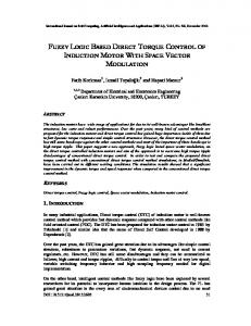
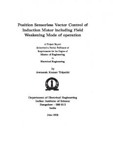
techniques or when the input information is described qualitatively, inexactly or with uncertainty [4]. In complex nonlinear systems, like robot axis driven by induction motors, this characteristic are often met. That’s why a fuzzy logic based controller was designed and implemented for the active current loop. The block diagram of the fuzzy controller is presented in Fig. 2. It uses three linguistic variables, two imputs, e0 and ∆eo and one output u0. To represent fuzzy data, triangular fuzzy number were used. So, the imput variables are the speed error ∆n and the change of the speed error and the output is the imposed active component of the stator current, i∗sqλr. The input variables are computed at each sampling step. The designing algorithm of a fuzzy-logic based controller is presented in Fig. 3. The fuzzy rules this paper is concerned with, are based of seven linguistic values presented in Fig. 4 and of which triangular fuzzy numbers corresponds. Control rules can be deduced in various ways [6], [8]. There have been designed based on experts experiments and knowledge [7]. For the fuzzy membership functions of the linguistic variables E, DE and U, presented in Fig. 2, by using "IF-THEN" control rules and using for the comand U the center of gravity defuzzyfication method, the output/error u=f(e) (Fig.5.a) and output/ error-variation u=f(∆e) (Fig.5.b) characteristics are presented. The u=f(e,∆e) characteristics are presented in Fig. 6. The optimal inference rules and the final parameters of the fuzzyfication block were obtained with the help of software designing and simulation tools for fuzzy-logic, like Fuzzy-Shell and ANSIM [9].
E Ke
FUZ
+
FUZZY CONTROL RULES
KIu +
U
∆t
DEF Ku
Fig. 2 Block diagram of the fuzzy-logic based speed controller
150
+
u=i*sqλr
+
3rd International Symposium on Electrical Engineering and Energy Converters
September 24-25, 2009, Suceava µE
System description
NB
NM
NS
ZE
PS
PM
Input/output variables
PB
E -1
0
1
Domain of definition µ DE
Membership functions
NB
NM
NS
ZE
PS
PM PB
Fuzzy rule base DE -1
0
1
Fuzzy operators and defuzzyfication method µU
Simulation
No
NB
Performance criteria?
NM
NS ZE PS
PM
PB
U -1
0
1
Yes
Fig. 4 Fuzzy membership functions (fuzzy numbers) of the linguistic variables E, DE and U
Fig. 3 Designing algorithm of a fuzzy controller The block of the fuzzy control rules has been implemented by means of a look-up table. The content of the look-up table is off-line computed and so, the demand for on-line computation made on the digital system is considerably relaxed. Hence, a very short computation time of this fuzzy-speed controller. For defuzzyfication, the center-of gravity method was used, applied to the lingvistic variable U. The real value obtained "u" represents the imposed active component of the stator current (i*sqλr in Fig. 1). The gain coefficients Ke and K∆e have to scale the real variables e and ∆e so that the fuzzy variables E and DE are defined in the domain [-1, 1]. The output gain Ku and integral coefficient KIu applied to the defuzzyfied control value generate the imposed active component of stator current.
IV.
HARDWARE AND SOFTWARE SYSTEM
The complete schematics of the used hardware are shown in Fig. 7. The main parts are the computing system, the three phases PWM based converter, the tested induction motor, a DC motor used as load and the current and speed sensors. The computing system is a Motorola MC68000 processor based motion control board. A fixed-point processor was used because of the performance/cost ratio. The control board has to receive the inputs from the process (the angular velocity), to perform the field-oriented based strategy and to transfer the output commands (the three imposed phase currents) to the converter.
u
u
e
0
∆e
0
0
0
a.) Command/speed error
b.) Command/speed error variation
Fig. 5 Output/input characteristics of the fuzzy controller
151
u
e
load torque was simulated by using a 10 kW DC machine. The IM motor parameters are presented in Table I. The field-oriented control algorithm with fuzzy speed controller was implemented on the drive system presented in Fig. 1. The structure was simulated using the ANSIM simulation software [10]. Fig. 8-11 present simulated results, for a speed step of 2000 rpm, using the fuzzy-logic based controller. The imposed speed is over the rated one, so the machine works in the flux-weakening region (to see in Fig. 11 on the flux producing stator current component isdλr). TABLE I. PARAMETERS OF THE INDUCTION MACHINE Parameter
0
Value
Output power
PN = 6,5 kW
Stator voltage (line)
0
Us= 322 V
Stator current
∆e
Fig. 6 Diagram u=f(e,∆e) of the fuzzy PID controller
Is = 19 A
Rotor speed
nr = 1500 rpm
Maximal speed
To achieve efficient software, a combination of high-level language, which should optimize in real-time applications the memory space requirements of RAM and ROM with assembly language, which optimize the run-time, and the hardware features of the CPU core must be used. The monitor program and the input/output management software is written in the 68000 assembly language and the control software for the two feedback control loops is written in C language. The look-up tables of the fuzzy controller and the dynamical parameters of the induction machine are off-line computed and mapped in the memory. V.
SIMULATED AND EXPERIMENTAL RESULTS
The experimental system is composed of a SIEMENS three-phase cage rotor induction machine having the commercial 1PH5107-4CF4-Z type and an AEG converter from the MINIVERTER 10/500 family. The
nmax = 8000 rpm
Torque
MN = 41,4 Nm
Motor inertia
J0 = 0,024 kgm2
Stator resistance (at 20 C°)
Rs = 0,359 Ω
Rotor resistance (at 20 C°)
Rr = 0,289 Ω
Stator reactance (at 50 Hz)
Xs = 15,701 Ω
Rotor reactance (at 50 Hz)
Xr = 15,406 Ω
Mutual reactance (at MN)
XmN = 14,7 Ω
Mutual reactance (at M0)
Xm0 = 14,3 Ω
At 0.55 sec. a load torque step of 35 Nm is imposed. The machine response can be seen in the stator frequency evolution in Fig. 9 and in the torque producing stator current component isqλr in Fig. 10. The experimental results have been obtained by implementing the control algorithms on the DSP computer system presented in figure 7. For a rated speed step, the dynamic behavior of speed and stator current is presented in Fig. 10 for the fuzzy speed controller.
CONTROL BOARD RAM
ROM D/A (12)
MC 68000 VT 100 Terminal
Serial I/O
D/A
i*sd i*sq
PWM converter
2/3 state variable
(8)
IM MC 68901
74 LS 2000
Trans.
Load Fig. 7 Block diagram of the motion control board with MC68000
152
3rd International Symposium on Electrical Engineering and Energy Converters
September 24-25, 2009, Suceava
Simulated results of the induction motor with fuzzy-logic speed controller for a 2000 rpm speed and a 35 Nm torque step.
Stator frequency fs (Hz)
Rotor speed nr (rpm)
Fig. 8 Speed response
Active stator current isqλr (A)
Fig. 9 Stator current frequency
Reactive stator current isdλr (A)
Fig. 10 Torque-producing component of the stator current
Fig. 11 Reactive component of stator current
Experimental results of the induction motor with fuzzy-logic speed controller for a 1500 rpm speed step.
Fig. 12 Active component of the stator current (1) and speed (2) at a imposed value of 1500 rpm, by using a fuzzy speed controller
153
ACKNOWLEDGMENT VI.
CONCLUSION
The test results demonstrate that the drive system with the indirect vector controlled induction motor and fuzzy speed controller has good dynamic behavior in a high range of speed (from -6000 rpm to 6000 rpm). The control software has a shorter running time and the system seems to be more robust than with a PI speed controller, but the optimal designing of the controller is more difficult. By using a fixed-point processor based configuration we have a relative great computing speed and a good performance/cost ratio. We can conclude, the advantages and disadvantages of the designed and implemented control structure are:
• •
•
154
robustness of control; short computing and response time, but needs increased designing efforts to obtain an optimal controller; lower control precision than with linear controllers, but good enough for many industrial applications.
The authors would like to acknowledge the Alexander von Humboldt Foundation - Germany for their support. REFERENCES [1] Leonhard W., Control of Electrical Drives, Springer-Verlag, Berlin, 1985. [2] Kelemen A., Imecs M., Vector Control of Induction Machine Drives, Vol. 1, OMIKK Publisher, Budapest, 1991. [3] Bose B. K., Power Electronics and AC Drives. Prentice Hall, Englewood Cliffs, New Jersey, 1986. [4] Pedrycz W., Fuzzy Control and Fuzzy System. John Wiley & Sons, Chichester, New York, 1989. [5] Kunz U., Regelung elektrischer Antriebe. Vorlesungsskript, Univ. of Siegen, Germany, 1992. [6] Wiesner R. S., "Optimal rotor flux regulation for fast-accelerating induction machines in the field-weakening region", IEEE Transactions on Industry Applications, Vol.34, No.5, pp. 1081-1087, 1998. [7] Birou I., Imecs M., "Speed control of induction motor drive with fuzzylogic controller, based on a DSP computing system", Proceedings of the International Symposium on Power Electronics, Electrical Drives, Automation and Motion SPEEDAM'2000, Ischia, Italy, pp. A1.19 – A1.24, 2000. [8] Wang L., Adaptive Fuzzy Systems and Control. Design and Stability Analysis. Prentice Hall, Englewood Cliffs, New Jersey, 1994. [9] Tilli T., Fuzzy-Shell für Windows. Version 1.2, Franzis-Verlag, Munchen, 1993. [10] * * * ANSIM Simulation Software, Department of Electrical Drives and Control, University of Erlangen-Nurnberg, 1989.