JPEG2000–based Compressed Multiresolution Model for Real-time Largescale Terrain Visualization Egor Yusov*, Vadim Turlapov**, *Intel Corporation & Nizhny Novgorod State University **Nizhny Novgorod State University, Nizhny Novgorod, Russia
[email protected],
[email protected]
Abstract
regions are. An overview of different terrain rendering approaches is given in the following section.
This paper presents an effective compressed multiresolution model for interactive large-scale terrain rendering. In contrast to previous approaches, our model enables construction of adaptive terrain triangulation that takes into account local surface features and, at the same time, supports compact representation of the elevation data. The model enables fast extraction of the certain terrain area height field approximation with the specified resolution from the compressed form that is essential for real-time viewdependent rendering. The core structure of the proposed approach is the quadtree. Each quadtree node represents the square patch that approximates some terrain region with the specific accuracy. Each patch is assigned a compact data that is sufficient to incrementally refine its triangulation and height field and obtain the next-finer approximation. Progressive representation of the elevation data uses the JPEG2000 image coder to compress the quantized differences between the values predicted from the coarser approximation and the exact elevations. The algorithm enables constructing compressed representation with the controlled maximum or root-mean-square world space error. This imposes the strict bound on the screen-space error when rendering the simplified model. Due to the high granularity of the LOD selection, the algorithm is not CPU-consuming and fully exploits the power of modern graphics hardware. The algorithm was tested on different data sets; the experiments proved its effectiveness.
Another problem related to the massive terrain dataset handling is that the size of the height field can easily exceed memory capacity. The usual way to cope with this problem is to store all data on the disk and upload the desired regions as necessary. However, such approach requires a lot of disk space and complicated out-ofcore memory management algorithms. The alternative way is to keep the elevation data in a compressed form. In this case all data can be stored in RAM and necessary regions can be extracted at run time.
Keywords: interactive terrain visualization, multiresolution representation, data compression, quadtree, wavelet transform, JPEG2000.
1. INTRODUCTION Real-time large-scale terrain visualization is a complex and challenging task and it is an important component in a number of practical applications. These applications include virtual environments, computer games, flight or drive simulators, geographical information systems, landscape editors and other. The terrain surface is most commonly defined by the height field, which is a set of elevations measured in the nodes of a regular grid. For the large terrain area such height field may contain billions of elevation samples and even the highest-end graphics platforms are not able to render the complete terrain model at interactive frame rates. To effectively render large terrains, a number of dynamic multiresolution models have been developed during the last years. The proposed algorithms adapt the terrain tessellation based on local surface roughness and view parameters to dramatically reduce the model complexity without significant loss of visual accuracy. In these algorithms planar and distant terrain areas are assigned larger triangles than sharp and close to camera
Though a lot of works on constructing adaptive terrain geometry exist, just a few publications are devoted to effective elevation data management. In this article we present an efficient terrain data compression algorithm that is naturally incorporated in our previous adaptive terrain simplification and rendering approach [21]. In the base method, the geometry of the whole multiresolution hierarchy is encoded into compact progressive form. This paper presents an extension of the base multiresolution model that progressively encodes the elevation data as well and significantly reduces memory requirements.
2. RELATED WORK A number of different large-scale terrain rendering approaches have been proposed during the last years. The majority of works concentrate on the problems of constructing adaptive terrain triangulation that takes into account local surface roughness and camera view parameters. Some of such algorithms generate irregular triangulations. For example, two approaches based on the principal of 2D-Delaunay triangulation are presented in [1] and [2]. Other approaches that allow arbitrary connectivity are presented in [3] and [4]. Other algorithms use hierarchical data structures. A good survey of different hierarchical terrain simplification approaches is presented by R. Pajarola in [5]. The first algorithm that produces continuous LOD triangulation is presented by P.Lindstrom et al. in [6]. The algorithm is based on the vertices quadtree. The ROAM (Real-Time Optimally Adapting Meshes) algorithm presented by M.Duchaineau et al. in [7] is conceptually very close to the method described in [6] and uses triangle bintree hierarchy. The ideas proposed in [6] and [7] were further developed in [8], [9], [10]. The next step in evolution of terrain rendering algorithms was made when the power of graphics processors increased significantly comparing to that of CPUs. Simplification granularity shifted from single vertices and triangles to more complex primitives (triangle clusters, batches, aggregates etc.)
The first method that effectively utilizes power of graphics processors is called RUSTiC (ROAM Using Surface Triangle Clusters) and is presented by A. Pomeranz in [11]. In [11] it is proposed to replace single triangles from the bintree hierarchy of the ROAM algorithm from [7] with more complex elements called clusters. Each cluster is a small triangulated mesh. This idea was further developed by J. Levenberg in [12], where it was proposed to cache such small meshes (which in [12] are called aggregate triangles) in the fast video memory to assure the most effective rendering by the graphics card. Extensions of quadtree-based algorithms, that use square patch as a base element for the adaptive mesh construction, are presented in [13] and [14]. The main idea proposed in [11] and [12] was further improved by P. Cignoni et al in [15]. In [15] it was proposed to replace single triangle from the bintree hierarchy of the ROAM algorithm with small TINs (triangulated irregular networks) called batches. In [16] this algorithm was extended to successfully render the planet-sized terrains in real time. Noteworthy that in approaches presented in [15] and [16], the whole hierarchy requires a lot of disk space and constant disk access at run time. A radically new terrain rendering approach was proposed by F. Losasso and H. Hoppe in 2004 in [17]. The method is called geometry clipmaps. It treats the terrain as a set of nested regular grids centered about the camera position and completely ignores the local adaptability. The authors prove this decision by the fact that the performance of graphics processors has reached such a high level that the task of constructing adaptive triangulation is no longer important. And the main problem is to adaptively feed the graphics pipeline. In [18], a GPU-based implementation of the geometry clipmaps framework is presented. The implementation is enabled by the shader model 3.0 and vertex textures.
ing method presented in [21]. The brief description of the base algorithm is given in the following section.
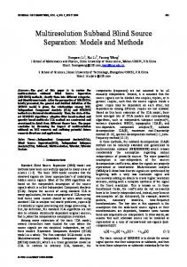
3.2 The Base Approach 3.2.1 Multiresolution representation of the source elevation data The proposed method consists of two phases: the preprocess stage and the run-time stage. At the preprocess stage, the algorithm constructs initial multiresolution representation of the source elevation data. During this process the source height field of the size N × M vertices is filtered into multi-layer pyramid, a mipmaplike structure (Figure 1.a), which is similar to the structure used in the geometry clipmaps framework [17]. For the convenience, the sizes N and M are set to power of two. Each layer of the pyramid approximates the source data with diminishing accuracy and has two times lower resolution in each grid dimension than the underlying level does. To coarsen each layer and construct the next coarser approximation, we use order 4 Neville interpolating filter [22], see [21] for more details. The same filter is also used in the C-BDAM approach [19]. The pyramid can also be interpreted as a vertices quadtree where each vertex in the coarse level has four children in the finer level (Figure 1.b).
level 0 (root) vertex level 1 vertices level 2 vertices
Among publications listed above, the terrain compression algorithms are considered in [17], [18] and [19]. The method proposed in [19] extends the previous author work presented in [15] and [16]. The method is called C-BDAM (Compressed Batched Dynamic Adaptive Meshes) and uses wavelet transform to compress the terrain data. The geometry clipmaps framework [17] adapts the image compression algorithm presented in [20] to compress the elevation data.
Figure 1: Multiresolution representation of the source data. Vertices in each pyramid level are identified by the triple index (i, j, k), where k ∈ {0,1,..., Dhf − 1} denotes the resolution level and
3. ALGOPRITHM DESCRIPTION
the height field quadtree). Level 0 is the coarsest approximation represented by the single root vertex; level Dhf − 1 is the original
3.1 Motivation
height field and provides the finest representation.
As we mentioned in Section 2, a lot of works on adaptive terrain simplification [12-16] as well as successful terrain compression approaches [17, 19] exist. However, none of works combines adaptive triangulation with the data compression in one multiresolution model. The methods presented in [12-16] propose effective adaptive terrain tessellation algorithms, but they do not use compressed representation. On the other hand, the C-BDAM approach [19] exploits terrain compression, but in this method each triangle patch from the hierarchy has the same regular triangulation. Any local surface roughness increases tessellation density of the whole patch. As the result, a too redundant adaptive triangulation is generated. The geometry clipmaps approach [17, 18] utilizes compressed representation, but it ignores local terrain features at all: the triangulation depends solely on camera position.
3.2.2 The meta quadtree
We propose the multiresolution model that enables constructing adaptive terrain triangulation and supports compact compressed representation of the elevation data. The algorithm described in this article extends the adaptive terrain simplification and render-
(a)
(b)
i, j ∈ {0,1,...,2k − 1} denote the vertex position in the layer’s grid. Dhf denotes the number of levels in the pyramid (or the depth of
In our approach, as in the algorithms described in [11-16], the LOD selection is performed on a per-block basis to reduce CPU load and fully exploit the power of modern graphics processors. The core structure of the algorithm is the quadtree; each quadtree node represents the patch that covers the square terrain region. To distinguish this structure with the vertices quadtree mentioned in the previous section, we call it meta quadtree. Nodes that lie in the finer resolution levels cover smaller terrain regions with the higher accuracy, while nodes in the coarser levels cover larger area with the lower resolution. Each quadtree node covers the same area as its four immediate children, but child nodes provide more accurate approximation. Each patch in the meta quadtree specifies a multiresolution representation of the local terrain area that it covers. This multiresolution representation encompasses some subset of vertices from the whole multiresolution pyramid and forms a sub-pyramid (Fig-
ure 2.a). It can also be interpreted as a sub-quadtree (Figure 2.b). Each such sub-pyramid has a fixed number of levels, which is denoted by D p . The number of levels in the meta quadtree Dm , in the patch sub-pyramid D p and, in the whole multiresolution representation Dhf ,
are
bound
by
the
following
rela-
tion: Dm = Dhf − D p + 1 . The sub-pyramid of the patch that lies in the meta quadtree level q and has horizontal order m, and vertical order n encompasses the following set of layers: {Lkm ,n ,q , k = 0,1...D p − 1} , where Lkm ,n ,q is
the k-th level of the patch sub-pyramid and comprises of the following vertices: Lkm ,n , q = {hi , j , k + q } where
(1)
i ∈ {n ⋅ 2 − 2, ..., ( n + 1) ⋅ 2 + 2}
(2)
j ∈ {m ⋅ 2 − 2, ..., ( m + 1) ⋅ 2 + 2}
(3)
k
k
k
k
Note that each pyramid layer is extended by 2 additional vertices behind each patch boundary to seamlessly stitch neighbor patches and correctly perform texture and normal mapping, see [21].
Camera
Figure 3: Example of an adaptive terrain approximation with the square patches. The base algorithm presented in [21] stores compact progressive data for each meta quadtree node, which enables reconstructing adaptive triangulation of its children. In this paper we extend the progressive representation with the data necessary to reconstruct child elevation data as well.
Our terrain compression algorithm is based on the JPEG2000 image coding scheme. JPEG2000 has been chosen because it proved itself to be one of the best image compression algorithms available for the moment. It outperforms the previous DCT-based JPEG compression in terms of image quality and compression ratios [23], besides it does not suffer from blocking artifacts typical for the JPEG-based compression at high compression ratios. Furthermore, the JPEG2000 standard offers efficient lossless compression scheme. Below provide the basic information about the JPEG2000 standard.
3.3 The JPEG2000 Image Coding Standard The flow diagram of the encoder is presented in Figure 4. Below we briefly describe each stage of the encoding process. More detailed information about JPEG2000 can be found in [24], [25]. (a)
(b)
Figure 2: Multiresolution representation of the terrain area covered by some patch and its relationship to the whole multiresolution representation of the source elevation data: a) sub-pyramid and b) sub-quadtree. It follows from (1) that the finest level k = D p − 1 of the mul-
tiresolution representation associated with the patch, which lies in meta level q, consists of vertices from the level q + D p − 1 of the whole multiresolution representation. This level contains maximum elevation information that is available for the patch. Multiresolution representation of the area covered by the patch enables constructing adaptive triangulation that takes into account local surface features. Flat areas can be approximated by the vertices from the coarser levels while sharp features must be represented by the vertices from the fine levels to preserve accuracy. The adaptive triangulation construction algorithm is thoroughly discussed in [21]. Each quadtree node is assigned a geometric world-space approximation error, which is calculated at the preprocess stage. At the run-time stage, the screen-space error estimation is calculated for each quadtree block using camera view parameters. Basing on these values, the algorithm selects the desired patches that approximate the surface with the user-specified tolerance (Figure 3).
Figure 4: JPEG2000 encoding diagram. At the pre-processing stage, the original image is pre-processed so that the discrete wavelet transform (DWT) can be properly performed. This step consists of three sub-stages: 1) tiling, which is partitioning the source image into rectangular and nonoverlapping tiles of equal size; 2) level offset, which ensures that the input sample data has a nominal dynamic range centered about zero and 3) irreversible color transform (ICT), which converts the input RGB data into the YCrCb format. Discrete Wavelet Transform (DWT) is used to decompose each image tile into its low and high subbands. The DWT [22] is performed many times, so that the resulting coarser representation obtained by applying low-subband filtering for rows and columns (LL-subband) is further decomposed by the DWT.
At the quantization stage, the wavelet coefficients are quantized using a uniform quantizer with the dead zone. At the embedded image coding stage, the subbands of each tile are partitioned into small code blocks of equal size (e.g. 64x64 or 32x32 samples), which are encoded independently using a context-based adaptive binary arithmetic coder. Rate control is the process by which the code-stream is altered so that a target bit rate can be reached. At
the final bit-stream organization stage, the compressed bit streams of each compressed block are organized into the final compressed image data composed of packets. The JPEG2000 decoder works symmetrically to the encoder. The wavelet coefficients contained in the packets of the bit-stream are dequantized, processed using inverse DWT, and then the reverseICT is performed.
h7, 0
h7 ,7 * h11 ,0
h6,0 h10* ,0 h9*, 0 * h5,0 h8,0
h7*, 0
3.4 Terrain Compression Algorithm As it was mentioned earlier, the lowest level of the patch subpyramid contains maximum elevation information that is available for that patch. This level is represented by the grid heaving D −1 D −1 ( 2 p + 4) × ( 2 p + 4) vertices (see (1)-(3) when k = D p − 1 ).
h4,0 h6*,0
We denote this grid by H Coarse (indices i and j are shifted, and the third index is omitted for convenience):
h3*, 0
H
Coarse
= {hij | i, j ∈ {0,1,...2
D p −1
+ 2,2
D p −1
All levels of the child patch sub-pyramids excepting the finest levels can be obtained by copying vertices from the parent patch pyramid (vertices from the level k of the parent patch constitute the level k-1 of the children). The main challenge is to reconstruct the finest levels that actually contain additional information. The finest levels of four child patches together cover the same area as H Coarse but provide higher resolution. We denote this set by H Fine : H Fine = {hij* | i, j ∈ {0,1,...2
Dp
+ 2,2
Coarse
Dp
h5*, 0
h3,0 h4*,0
h2, 0 h2*,0
+ 3}
If the elevation information contained in the patch sub-pyramid is insufficient to approximate the terrain surface with the desired accuracy (the screen-space error exceeds the threshold), the patch needs to be refined. In this case, the patch is replaced with its four immediate children, which contain more information about the surface and can provide the desired approximation. To accomplish this task, it is necessary to reconstruct the multiresolution representations associated with the child patches. The child triangulations can be obtained as described in [21]. Here we describe a method to reconstruct the child elevation data.
+ 3} Fine
Note that vertices from H and H lie in different levels of the whole multiresolution representation. Figure 5 shows relationship between the finest levels of the multiresolution representations associated with the parent patch and its children. The finest resolution grid of the multiresolution representation D −1 D −1 associated with a patch contains ( 2 p + 4) × ( 2 p + 4) = 8 × 8 vertices. (In practice, patch quadtree has much more levels. For example, when D p = 9 , the grid contains 260 × 260 vertices and memory overhead caused by 2 additional vertices is less than 3%). Double line in Figure 5 bounds the area covered by the patch and its four children. Vertices from the finest level of the parent patch sub-pyramid ( H Coarse ) are denoted by crosses and are labeled by hi , j ; vertices from the finest levels of the child subpyramids, which constitute H Fine , is denoted by circles and are labeled by hi*, j . Dotted line defines vertices that constitute the finest resolution grid of each child patch sub-pyramid. Note that they overlap.
* h11 ,11
h1*, 0
h1, 0 h0,0
h0*, 0 h0*,1 h0*, 2 h0*,3 h0*, 4 h0*,5 h0*,6 h0*,7
h0,1
h0, 2
h0,3
h0, 4
h0*,8 h0*,9
h0*,10 h0*,11
h0,5
h0,6
h0,7
Figure 5: Relationship between the finest levels of the child patch sub-pyramids and the finest level of the parent patch sub-pyramid. In the example shown in Figure 5, the number of levels in the patch sub-pyramid (or in the patch sub-quadtree) is 3: D p = 3 .
The first step of the compressed representation construction process is predicting values in H Fine . The prediction is performed by linear interpolation of values stored in H Coarse onto the samples in H Fine . The linear interpolation is chosen because it can be effectively performed by every modern graphics processor (for example, the Sample() function in the HLSL performs this ~ task, see Section 4). We denote this predicted set as H Fine : ~ ~ D D H Fine = {hij* | i, j ∈ {0,1,...2 p + 2,2 p + 3}
At the next step, the algorithm constructs difference layer that ~ contains discrepancies between the predicted values from H Fine Fine and the exact values from H . We denote the difference layer as D: ~ D −1 D −1 D = {d ij = hij* − hij* | i, j ∈ {0,1,...2 p + 2,2 p + 3} The exact values hij* come from the corresponding layer of the whole multiresolution pyramid. At the next step, the minimum and maximum values in the D are identified:
d min = min d ij , d max = max d ij And the 32-bit floating point difference layer D is quantized to 8bit integer according to the following rule: dˆij = [( d ij − d min ) /( d max − d min ) ⋅ 255] The resulting quantized difference layer is denoted by Dˆ . At the next step, it is compressed using the JPEG2000 coding algorithm described in Section 3.3 and compressed bit stream is stored in the database as well as d min and d max values. Note that since difference values constitute a monochrome image, the ICT is not performed. At this step, the main loss of data takes place. The ap-
proximation accuracy is controlled by adjusting compression ratio as described in Section 3.4.1. To eliminate error accumulation, we reconstruct the finest resolution levels of the child patches after compressing the data. Since compression scheme is lossy, the resulting reconstructed set differs from the original exact set H Fine . We denote the reconstructed set by H
Fine
. To calculate H
Fine
, we decompress the bit
stream and obtain the reconstructed quantized difference layer D . We then de-quantize this layer using d min and d max values, and Fine ~ add the layer to the predicted grid H Fine . The resulting set H is the one that will be obtained at the run-time stage. Processed coarser level
Reconstructed grid H
Predicted grid ~ H Fine
Bilinear interpolation
Coarse
this algorithm, the H Fine set is quantized and is compressed as is without any prediction from the coarser level patch. The 32-bit floating values from H Fine are quantized to n-bit integer values and then compressed using the JPEG2000 image coding algorithm. The comparison of this algorithm with the progressive compression scheme is presented in Section 5.
3.4.1 Controlling compression process and compression criteria While a lot of criteria bound the approximation error of the reconstructed signal with the approximation error in wavelet space in L2 sense, there is no one that bounds the distortion in L∞ sense [28]. However, the L2 (or root-mean-square) error is not always satisfactory when dealing with the terrain compression. For example, the geometry clipmaps approach [17, 18] is not able to provide the guaranteed maximum absolute world space error. To solve this problem, we adaptively adjust the compression ration to satisfy the desired criterion (maximum absolute or root-meansquare error in the world space). The diagram of the adaptive compression algorithm is presented in Figure 7.
Calculating difference layer
Exact grid
H Fine Calculating minimum and maximum values d min and d max , quantizing difference layer
Difference layer D
d min , d max Quantized difference layer Dˆ
d min
d max
Decompressing, de-quantizing difference layer
Compressing difference layer with JPEG2000 image coder
Compressed bit stream
Data base
Reconstructed ~ difference layer D
Reconstructing grid H using H
Coarse
Fine
Figure 7: Finding optimal compression ratio flowchart. After compressing the patch data, we reconstruct data and check the criterion. If the criterion is not satisfied, we adjust the compression parameter. This scheme enables finding the best approximation parameter for each terrain patch.
Reconstructed grid
~ and D
H
Fine
Compressing the next level using
H
Fine
4. IMPLEMENTATION DETAILS
as input
Figure 6: Progressive coding algorithm flowchart. Terrain data compression is performed top-down using recursive quad tree traversal algorithm. The algorithm starts from the root node that provides the coarsest approximation. The finest resolution level of the coarsest patch sub-pyramid is stored as is without Fine
compression. To eliminate error accumulation, the H set obtained at each step of the compression process serves as the input for the next step (at the next step, it is treated as the H Coarse set). The compression algorithm flowchart is presented in Figure 6. To demonstrate advantages of progressive compression scheme, we also implemented the direct terrain compression algorithm. In
The proposed terrain data compression algorithm has been integrated with the adaptive terrain simplification method presented in [21]. The test system is written in C++ in Microsoft Visual Studio .NET environment on the base of Microsoft DirectX10 and Shader model 4.0. In our current implementation, the extraction of difference data from the compressed bit-stream is performed on the CPU. To hide processing time and stabilize the system performance, the algorithm extrapolates the camera trajectory and anticipates its future position to extract the desired elevation data ahead of time. Furthermore, to minimize Direct3D resource creation overhead, the resource cache is used. The resources are not
released when they are no longer needed, but placed in the cache and re-used when they are needed again. The JPEG2000 codec in our system is implemented using the Intel Integrated Performance Primitives library. This library implements different media processing algorithms using SIMD instruction set (SSE, SSE2, and SSE3) to achieve high performance. While difference data is extracted from the compressed bit-stream on the CPU, the residuals can be added on the GPU in a pixel shader. In this case, predicted values can be obtained by sampling the texture with the bilinear filtration. To get the difference data, it is enough to read an 8-bit difference texture, since the hardware automatically scales the [0..255] range to the [0..1] diapason. The only thing we have to do is to scale the obtained value to the desired range [ d min , d max ] and to add it to the predicted coarse value. Normal maps in our system are generated on the GPU at the refinement stage and do not require additional storage. The GPU also performs geomorph to hide LOD switches (see [21]), and performs surface texturing.
5. RESULTS 5.1 Compression
The compressed multiresolution representation of the first data set was constructed using the patch size of 256x256 vertices ( D p = 9 ). In the first experiment, the data was compressed with the maximum world space error of 1 meter that is 3% of the height field spacing. Table 1 shows the compression ratios, maximum absolute difference and root-mean square differences between the original data set and the reconstructed data set in meters. The last column shows the peak signal-to-noise ratio (PSNR). Quant depth
Progressive
Quant depth
Compress. Max abs. ratio diff.
rms diff.
PSNR
Yes
8
14.32
2.9995
0.4245
80.2 DB
No
12
10.85
2.9993
0.4422
79.9 DB
Table 2: Compressing the Puget Sound data set with 3 meters maximum world space error. In case of immediate encoding, the quantization depth should be much higher than that of the progressive encoding to keep the desired quality. In this case progressive encoding brings 1.3x compression gain.
In the next experiment, the data set was compressed with the 3.0 meters maximum rms error, the patch size was 128x128 vertices. The results are presented in Table 3. Progressive
Quant depth
Compress. Max abs. ratio diff.
rms diff.
PSNR
Yes
8
104.34
46.57
2.76
64 DB
No
12
74.1
49.49
2.68
64.26 DB
Table 3: Compressing the Puget Sound data set using 3 meters rms world space error. Comparison with other algorithms is rather difficult, because we do not have the same data set. For example, in [19], authors used a height filed with 10 meter spacing. With one meter rms error threshold they reported 57x compression ratio.
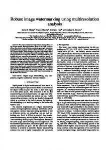
Figure 8: Puget Sound and Grand Canyon data sets rendered with our system. We have experimented with two different data sets to test our compression scheme. The first one is the Puget Sound and the second one is the Grand Canyon data set (see Figure 8). Both are 8192x8192 32-bit floating point girds at 30 meters spacing. The original data occupies 256 MB of disk space.
Progressive
In the next experiment, the data set was compressed with the guaranteed maximum world space error of 3.0 meters. The compression results are presented in Table 2.
Compress. Max abs. ratio diff.
rms diff.
PSNR
Yes
8
7.2
0.9993
0.1809
87.7 DB
No
12
5.69
0.9948
0.1655
88.4 DB
Table 1: Compressing the Puget Sound data set with 1 meter maximum world space error. As Table 1 shows, using progressive encoding algorithm improves compression ratio for this data set by a factor of 1.26.
In the next experiment, the quantized difference data was compressed using lossless encoding path that is supported by the JPEG2000 standard. The patch size is 256x256 vertices. Table 4 shows that the data set was reconstructed with the rms error of only 13 cm that is only 0.4 % of the height field spacing. Note that the error is caused by the loss of data at the quantization of difference data from 32-bit float to 8-bit integer. Progressive Yes
Quant depth 8
Compress. Max abs. ratio diff. 5.73
0.55
rms diff.
PSNR
0.13
90.5 DB
Table 4: Compressing the Puget Sound data set with lossless difference data compression. The Grand Canyon data set was compressed using three different criteria. In all experiments, the progressive encoding was used, the patch size was 256x256 vertices, and residuals quantization depth was 8 bit. The results are presented in Table 5. Criterion
Compress. Max abs. ratio diff.
rms diff.
PSNR 77.42 DB
Max abs error 3.0
12.3
2.9998
0.4635
Max rms error 3.0
69.05
58.29
2.7366
62 DB
No res. compr.
6.44
1.2936
0.2613
82.4 DB
Table 5: Compressing the Grand Canyon data set using different criteria. Table 5 shows that with compression ratio more than 69x, the data are compressed with 62 DB PSNR. In the residuals lossless compression mode, the data compressed with 6.44x ratio and differs from the original one with only 26 cm rms error.
5.2 Performance
Maximum Performance
We compared the performance of our algorithm with the performance of our implementation of the geometry clipmaps approach [17, 18]. The test platform was equipped with the Intel Pentium D 3.0 GHz processor, 2 GB RAM and GeForce 8800 GTS graphics card with 640 MB of video memory. In all experiments, the camera was moving along the predefined path. In geometry clipmaps approach, we used uncompressed terrain representation, so our implementation should work faster than the original one. Our original data set having size 256 MB was compressed to 19 MB. In both algorithms, the terrain was rendered using the same visual settings. The terrain was rendered into the 1024x768 window. In both systems, we implemented an atmospheric light scattering algorithm presented in [26], [27]. The comparison of the algorithms performance is presented in Figure 9 and Figure 10. In the first run of our algorithm, we used the screen space threshold of 4 pixels that provides quality equal to that of the geometry clipmaps approach with the clipmaps n=255 and the window size of 1024x768 pixels. The second run was performed with the screen space error of 2 pixels that provides much higher quality than the geometry clipmaps. Figures 9 and 10 show that our algorithm provides higher frame rates and rendering performance even with higher image quality. FPS
900 800 700 600 500 400 300
1100 1000 900 800 700 600 500 400 300 200 100 0 0.5
4
7.5
11
14.5
18
21.5
25
28.5
32
35.5
39
42.5
46
49.5 53
56.5 60
Time (seconds)
FPS
M∆/s
K∆/frame
Figure 11: Maximum rendering performance of our algorithm. Figure 11 shows that the average rendering performance of our system is 220 millions triangles per second (M∆/s), while peak performance is 262 M∆/s. The average scene complexity was 586,000 triangles. The average frame rendering rate was 407 fps, and it never dropped below 250 fps. Figure 11 shows that our algorithm does not CPU-bound and very effectively exploits power of modern graphics processors.
6. CONCLUSION AND FUTURE WORK We described an effective multiresolution model for interactive terrain rendering. The model encodes adaptive surface approximation at different levels of details and supports an efficient data compression. Our model enables constructing adaptive triangulation with the variable resolution that is minimally redundant, while other approaches that uses compressed terrain representation resort to regular triangulations or ignore local terrain feature.
200 100 0 0.5
4
7.5
11
14.5
18
21.5
25
28.5
32
35.5
39
42.5
46
49.5
53
56.5
60
Time (seconds)
Geometry Clipmaps
Our Method, 4 Pixels
Our Method, 2 Pixels
Figure 9: Comparison of the frame rates of the geometry clipmaps approach and our algorithm. M∆/sec
180 160 140 120 100 80 60 40 20 0 0.5
4
7.5
11
14.5
18
21.5
25
28.5
32
35.5
39
42.5
46
49.5
53
56.5
60
Time (seconds)
Geometry Clipmaps
Our Method, 4 Pixels
Our Method, 2 Pixels
Figure 10: Comparison of the rendering efficiency of the geometry clipmaps approach and our algorithm measured in million triangles processed per second. The reason for our algorithm to outperform the geometry clipmaps approach [17, 18] is that our algorithm caches the data in the video memory while geometry clipmaps permanently transfers data from the host to the GPU, which hinders performance.
To test maximum performance of our algorithm and explore effectiveness of GPU utilization, we rendered the scene with minimal GPU load. The scene was rendered without light scattering atmospheric effects, and simple height-based surface shading was used. The results are presented in Figure 11.
Our compression scheme is based on the JPEG2000 image compression standard that proved to be the one of the best image compression algorithms available for the moment. Our compressed representation greatly reduces the size of the elevation data so it can reside completely in system memory thereby avoiding the complexity of out-of-core memory management. The construction process allows direct controlling of the approximation accuracy using rms or maximum absolute world space error criterion, which is essential for terrain rendering. The model is well-optimized for the current graphics hardware and allows very efficient utilization of the GPU rendering performance. Our experiments showed that it outperforms such recent approach, as geometry clipmaps [17, 18] in terms of rendering frame rates and triangle processing performance. Our algorithm is not CPU bound and due to the efficient asynchronous implementation, it demonstrates a high rendering performance that is far enough for interactive terrain visualization systems. In our current implementation, the extraction of compressed residuals from the compressed bit-stream is performed on the CPU. The advances of the current graphics hardware enable executing complicated programs on the GPU. For example, the GPU-based implementation of wavelet transform is presented in [29]. One possible direction of our future work is to implement the decompression step entirely on the GPU to greatly decrease the CPU load. The other way of improvement is to procedurally generate the fine terrain details by using some sort of noise as the difference data rather than extracting it from the compressed form.
7. REFERENCES
Meshes for Terrain Rendering. Computer Graphics Forum, Volume 25(2006), Number 3
[1] Andreas Voigtmann, Ludger Becker, and Klaus Hinrichs. Hierarchical surface representations using constrained delaunay triangulations. In Thomas C. Waugh and Richard G. Healey, editors, Proc. 6th Int. Symposium on Spatial Data Handling, volume 2 of Advances in GIS Research, pages 848-867. Taylor & Francis, London, 1994.
[20] Malvar, Henrique. 2000. “Fast Progressive Image Coding without Wavelets.” In Data Compression Conference (DCC ’00), pp. 243–252.
[2] Cignoni, P., Puppo, E., Scopigno, R. Representation and visualization of terrain surfaces at variable resolution. The Visual Computer 13(5), 199-217, 1997. [3] De Floriani, L, Magillo, P. and Puppo, E. 1997. Building and traversing a surface at variable resolution. IEEE Visualization 1997, 103-110. [4] Hugues Hoppe. Smooth view-dependent level-of-detail control and its application to terrain rendering. In Proc. Visualization 98, pages 3542. IEEE, Computer Society Press, Los Alamitos, California, 1998. [5] Renato Pajarola. Overview of quadtree-based terrain triangulation and visualization. Technical Report UCI-ICS-02-01, I&C Science, University of California Irvine, 2002. [6] P. Lindstrom, D. Koller, W. Ribarsky, L. F. Hodges, N. Faust, and G. A. Turner. Real-time, continuous level of detail rendering of height fields. In Proc. SIGGRAPH 96, pages 109-118. ACM SIGGRAPH, 1996. [7] M. Duchaineau, M. Wolinsky, D. E. Sigeti, M. C. Miller, C. Aldrich, and M. B. Mineev-Weinstein. Roaming terrain: Real-time optimally adapting meshes. In Proceedings Visualization 97, pages 81-88. IEEE, Computer Society Press, Los Alamitos, California, 1997. [8] Renato Pajarola. Large scale terrain visualization using the restricted quadtree triangulation. In Proceedings Visualization 98, pages 1926 and 515. IEEE Computer Society Press, 1998. [9] Thomas Gerstner. Multiresolution visualization and compression of global topographic data. Technical Report 29, Institut für Angewandte Mathematik, Universität Bonn, 1999. to appear in Geoinformatica. [10] Renato Pajarola, Marc Antonijuan, Roberto Lario. QuadTIN: Quadtree based Triangulated Irregular Networks. In Proceedings IEEE Visualization 2002, pages 395-402. IEEE Computer Society Press, 2002 [11] Pomeranz A. A. ROAM Using Surface Triangle Clusters (RUSTiC). Master's thesis, University of California at Davis, June 2000. [12] Joshua Levenberg Fast View-Dependent Level-of-Detail Rendering Using Cached Geometry. In Proceedings IEEE Visualization'02 (Oct 2002), IEEE, pp. 259-266. [13] Roberto Lario, Renato Pajarola, Francisco Tirado 2003 HyperBlockQuadTIN: Hyper-Block Quadtree based Triangulated Irregular Networks. IASTED International Conference on Visualization, Imaging and Image Processing (VIIP 2003), pp. 733-738. [14] Schneider J, Westermann R 2006 GPU-Friendly High-Quality Terrain Rendering. Journal of WSCG ISSN 1213-6972, Vol.14, 2006, Plzen, Czech Republic [15] P. Cignoni, F. Ganovelli, E. Gobbetti, F. Marton, F. Ponchio, R. Scopigno 2003 BDAM - Batched Dynamic Adaptive Meshes for High Performance Terrain Visualization. Computer Graphics Forum, Volume 22(Sept. 2003), Number 3, pages 505-514. [16] P. Cignoni, F. Ganovelli, E. Gobbetti, F. Marton, F. Ponchio, R. Scopigno 2003 Planet-Sized Batched Dynamic Adaptive Meshes (PBDAM). In IEEE Visualization (2003), pp. 147-154. [17] Frank Losasso, Hugues Hoppe Geometry Clipmaps: Terrain Rendering Using Nested Regular Grids. ACM Transactions on Graphics (Proceedings of SIGGRAPH 2004) 23(3), pp. 769-776. [18] Arul Asirvatham, Hugues Hoppe Terrain Rendering Using GPUBased Geometry Clipmaps. GPU Gems 2. Addison-Wesley, 2005, ch. Terrain Rendering Using GPU-Based Geometry Clipmaps, pp. 27-46. http://research.microsoft.com/~hoppe/. [19] E. Gobbetti, F. Marton, P. Cignoni, M. Di Benedetto, and F. Ganovelli 2006 C-BDAM - Compressed Batched Dynamic Adaptive
[21] Egor Yusov, Vadim Turlapov GPU-optimized efficient quad-tree based progressive multiresolution model for interactive large scale terrain rendering. In Proc. GraphiCon’2007, pp. 53-60, Moscow, June 23-27, 2007 [22] Kovacevic J., Sweldens W.: Wavelet families of increasing order in arbitrary dimensions. IEEE Transactions on Image Processing 9, 3 (2000), 480-496. [23] Farzad Ebrahimi, Matthieu Chamik, Stefan Winkler, JPEG vs. JPEG2000: An objective comparison of image encoding quality, Proc. SPIE Applications of Digital Image Processing, vol. 5558, pp. 300-308, Denver, CO, August 2-6, 2004 [24] M. D. Adams, The JPEG-2000 Still Image Compression Standard, Tech. Rep. N2412, ISO/IEC JTC 1/SC 29/WG 1, September 2001. [25] Gray, Karen L. The JPEG2000 Standard, Paper, Technische Universitat Munchen Lehrstuhl fur Kommunikationsnetze. Munchen, Feb. 18, 2003. [PDF] [26] Preetham A.J, P. Shirley, and B. Smits. A Practical Analytic Model for Day-light. Siggraph proceedings 1999. The paper is available at: http://www.cs.utah.edu/vissim/papers/sunsky). [27] Hoffman N., and A.J.Preetham. Rendering Outdoor Light Scattering in Real Time. The paper is available at: http://www.ati.com/developer/dx9/ATI-LightScattering.pdf, 2002 [28] Yea S., Pearlman W.A. A wavelet-based two-stage near-lossless coder. In Proc. ICIP (2004), pp/ 2503-2506, 2004 [29] Tien-Tsin Wong and Chi-Sing Leung Shader Implementation of Discrete Wavelet Transform Shader X4 Advanced rendering techniques, Charles River Media, ch. Shader Implementation of Discrete Wavelet Transform pp29-37, 2006
About the author Egor Yusov is a graphics software engineer at Intel Corporation. He is also a Ph.D. student at the Nizhny Novgorod State University, Department of Computational Mathematics and Cybernetics. His contact emails are
[email protected] and
[email protected]. Vadim Turlapov is a professor at the Nizhny Novgorod State University, Department of Computational Mathematics and Cybernetics. His contact email is
[email protected].