1. LECTURE 10. Summary Loss Free. Pulse Width Modulated Converters and.
Introduction to Losses. I. Summary DC-DC PWM Converter. A. Single Inductor ...
1
LECTURE 10 Summary Loss Free Pulse Width Modulated Converters and Introduction to Losses I.
Summary DC-DC PWM Converter A.Single Inductor Converters With Only Source Resistance losses
II. Two inductor Converters A. General B. CUK Converter DC Transfer Function Analysis: M(D) III. Static and Dynamic Switching Loss Effects in PWM Converters A. General Switch Issues B. Static Converter Losses C. Power Loss Switching at fsw Due to Finite SwitchTimes 1. General Considerations 2. Easy Switch Analysis : Transistor Off and Diode on 3. Complex Switch Analysis: Transistor on and Diode Off a. With Diode Stored Charge b. Inductor Current Switching
2
I. Summary - PWM single inductor converters A. Eight circuit topologies and DC transfer functions M(D) where M(D) ≡ Vo/Vg = f(D). Its crucial to emphasize that we assume LOSS LESS CIRCUITS BELOW.
3
All Vo/Vg = M(D) above were obtained using D+D’=1 or the continuous conduction mode approximation. I I a. Charge balance on Cout: on D + off D' = 0 C C V (on) V (off ) b. Volt-sec balance on L: L D+ L D' = 0 L L Power Conservation Given that for steady state conditions Vo = M(D)Vg, one must realize that simple power conservation arguments then demand: Ig = M(D)Io Clearly, pin =pout
4
In a lossless converter, since Pin = Pout: Io
Ig
+
+ Vg
+ -
M(D)Io
M(D)Vg
-
Vo -
Where the symbol
is a dependent source, either V or I
By analogy with the familiar ac transformer we can represent this as an effective DC transformer as shown below with a turns ratio of M(D). The model development flow is then: (a) actual converter, (b) DC transformer, and (c) simplified DC circuits can then be made using transformer rules. 1
+ Vg -
M(D)
Io
Lossless DC Transformer +
Effective turns ratio Vo
1:M(D)
-
Next we will simply add a source impedance to the DC source to the converter and see how this effects V(out) by employing transformer rules.
5
(a)
R1 +
+ V1
Vg
Switching dc-dc converter
Vo
-
R
-
D (b)
R1
V1
1:M(D) +
+
Vg
Vo
-
-
R
M2(D)R1 (c)
+ M(D)V1
Vo
R
Example of use of the dc transformer model: (a) original circuit; (b) substitution of switching converter dc transformer model; (c) simplification by referring all elements to secondary side.
Including source impedance R1 we get: R Vout = M(D)V1 ← Voltage Divider R + M2 (D)R1 ⇒ For big values of M(D) be careful of innocent R1 as it may surprisingly effect the DC output. This occurs, for example, in a converter for a flash camera that goes from 1.5 V to 1500 V. That is M=1000 magnifies even small Rsource
6
M(D) lossless itself will change only when we include lossy L and C inside the converter itself. See section III below. C. RMS Values for Converter Waveforms 1. Square and Ramp Waveforms i waveforms Typical Transistor Waveform i
Irms =
1 T 2 Is dt ∫ 0 Ts s
I
Irms = I D DTs
D'Ts
t
Typical Diode Waveform i 2I
Irms = 115 . I D
I DTs
D'Ts t
The two above are among the simplest cases. Recall that in the big three circuits we have even more complex AC wave forms as those shown below from Lecture 4. We repeat only one BOOST circuit waveforms from lecture 4 below but the point is made that each waveform has a unique RMS value that Irms is a function of the duty cycle D. On the next pages we also review the converter topologies as well as the current flows in each switch position so that the full waveform is developed. It is left to the student to match waveforms to RMS calculations using Appendix 1 of Erickson.
7
II. Summary of 2 inductor, 2 capacitor PWM converters A. Overview Clearly converter topologies exist with two L’s and two C’s. We will restrict ourselves to those two L/two C topologies with only two active switches. The extra L and C allow for better filtering of V(fsw) as well as better protection from KVL and KIL violations. Analysis of the circuits for the DC
8
transfer function follows the same principles. All provide Vout from 0 to nVg.
Note: Of the above, only Cuk has negative Vout w.r.t. Vg and Vout varies from 0 to M(D)Vg for all of the double L/C converters.
B. Lossless Cuk converter M(D) analysis
9
This is a series cascade of a boost converter driving a buck circuit as shown below. Polarity reversal occurs between input and output. Cuk is the inventor of this 1970’s circuit. Note: 1. V1 is the voltage across C1. 2. Upper series switches are redundant.
+
V1
V1
V1
Boost converter supplying a buck converter
The top series pair of switches is redundant and are employed as shown below: Polarities below are for analysis only • Use Volt-sec balance on L1 and L2 • Use charge balance on C1 and C2. iL
C1
L1
v1
1
i2
-
+ Vg
L2
+ 2
C2
v2
R
Ideal Switch Circuit
-
iL
C1
L1
v1 Q1
i2
-
+ Vg
L2
+ D1
C2
v2
R -
Transistor/ Diode Switch Implementation
Actual Cuk: Vo = -Vg ⇒ we will find Vo = -f(D)Vg
10
Case 1:
D when Transistor on and diode off has one circuit topology
iL
C1
L1
L2
v1
Vg
D: SW position 1
i2 +
C1
C2
v2
R
+
-
Q1 on & D1 off
In: Energy stored in L1 via IL = I1 Out: Transfer energy from C1 to C2 via I2 Case 2:
D’when transistor off and diode on has a second, separate circuit topology
iL
L1
iC1
L2 +
+ v1
C1
Vg
vL2
D’: SW position 2
i2 -
+
iC2 C2
v2
R
-
-
Q1 off & D1 on
In: Energy stored in C1 via IL Out: Transfer energy from L1 to C2 via I2 DC analysis conditions Inductor volt-sec waveforms Capacitor I-sec waveforms vL1(t)
Vg
I1
iC1(t)
DTs D'Ts Vg - V 1
DVg + D’(Vg - V1) = 0
t
DTs
D'Ts t
I2
DI2 + D’I1 = 0
11
-V2
vL2(t)
iC2(t) I2 - V2/R (=0)
DTs
D'Ts
DTs
t
D'Ts
t
V1 - V 2
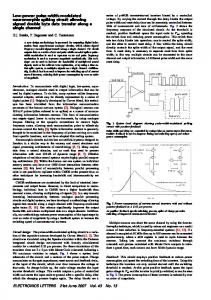
D(-V1 - V2) + D’(-V2) = 0 I2 - V2/R = 0 V D − D Yields 2 = − = Vg D' 1 − D D V D M(D) = 2 = − 0.25 0.5 0.75 1 Vg 1− D M(D)
-1 -2 -3 -4 -5
⇒ Inverting Vo from assumed polarity
Again initial polarities I2, V2 are assumed for analysis only. Same with I1 and V1 Knowing vL1, vL2 vs. time gives iL1, iL2 (steps) (ramps) i1(t)
iL1:
∆i1
I1 Vg/L1 (V -V )/L g 1 1
Follows assumed vL step waveforms
t DTs
D'Ts
t
iL2: -V2/L2 I1 i2(t)
∆i2 (-V1-V2)/L2
12
∆iL1 ≡
∆iL =
Vg 2L1
DTs or L1 ≡
V1 + V2 2L 2
VgDTs 2∆iL1
, so specify
∆ iL
to get L.
V + V2 DTs or L 2 = 1 2∆iL 2
From DC solutions: V1 = Vg/D’and V2 = Vg(-D/D’) L 2 (spec) =
1 D − ) D' D' DT s 2∆iL 2
Vg (
Vo V − D = − 2 spec sets D ≡ Vg Vg 1− D L 2 (spec) =
VgDTs 2∆iL2
Knowing ic1, ic2 vs. time gives vc1, vc2. (steps)
(ramps)
Since I2 ≡ vo/R is only DC then ∆ ic2 is non-pulsating, if we also neglect prior ∆ iL2 then ∆ vc2 = 0. This is not true! Actually we cannot do this. ∆iL2
∆vC2
From Lecture 4, ∆v c =
Classic Double Pole Low Pass Filter
∆iL 2 Ts ∆iL2 Ts and C(spec) = 8C 2 ∆v c 2 8 C 2
13
Use the I1 waveforms and integrate: v1(t) ∆v1
V1 I2/C1
I1/C1
I 1 ∆vc1 = 2 DTs 2 C1
t DTs
D'Ts
Now from DC analysis: V − D − D Vg I2 = 2 and V2 = Vg ⇒ I2 = R D' D' R ∆v c1 =
VgD 2 Ts 2D' RC1
, so C1(spec) =
VgD 2 Ts 2∆v c1RC1
III. Static and Dynamic Switch Loss in Real Converters A. General Switch Issues Clearly voltage drops across the energy storage inductor,VL, differ in lossless vs. lossy converters. ). The equivalent series resistance of inductors and capacitors add losses. In lossy converters efficiency is then a function of load current ,IL, while in lossless converters it is not . Also, su and sd of di/dt in the inductor for lossless converters will not be equal to that of lossy converters. Hence, M(D) changes from the lossless case and becomes M(d,losses) Switch devices also introduce losses. Thus, for example a diode alone adds both VD(on) + IonRD and this changes VL as well as sd slope.
14
Consider both DC and RMS currents and their static effects but neglecting dynamic switching losses:.. 1. Static or Non-switching power losses: Reactive elements: • Capacitors
• Inductors on cores
In practice parasitic R, L, and C components arising often make up half the circuit model components though they do not appear on the bill of lading. Resistance effects include: • RL of the inductor windings including skin effects. • Ron of the double-pole, double-throw switch devices from device characteristics such as Ron of the transistor or Ron of the diode. 1 • ESR of all capacitors = Rw + 2 w R leak C 2 •ESR effects for L These may appear in input or output circuits depending on converter topology and cause loss of power efficiency, η, from the ideal case where they are neglected. •Switch Device effects For example Von and Ron of semiconductor devices. See Chapter 5 of Erickson’s text • MOSFET’s • IGBT’s • diodes • GTO (Gate turn-off Thyristor) • MCT (MOS-Controlled Thyristor) Below we show the Von three switches:for MOSFET(highest value, for the IGBT, and for the BJT(lowest value).
15
Pin
Lossy Converter
η= Pout
Po Pin − Ploss = ; Pin Pin
typically 85 < η < 95% Both resistive and device losses contribute to loss of efficiency. In summary,wire resistance: IL2RL and IRMS ≠ IAV device losses due to Von of the diode and Ron(transistor) a. Diode Von is fixed at ≈2V and PD(sw) = IDVon (usually Ron of a diode is negligible) b. Transistor Ron(I) or fixed and Ptr = I2trRon (usually Von of a diode is negligible) On the next page we show the two extreme switch conditions: cutoff and saturation.
16
C. Finite Switching Losses at fsw 1. General Considerations Switching loss is not easily obtained only from a device data sheet and circuit conditions. First, lets recall that static state loss is to a first approximation zero. We also state that for now we will neglect switch drive losses. That is don’t forget that we have to drive the switch and this takes energy. The typical switch waveforms including gate drive are shown on the next page. In the ideal zero switching time case there is no loss due to transistor switching as we switch between two zero loss states. TR on: Va = 0, Ia = max, Ptr = 0 TR off: Va = max, Ia = 0; Ptr = 0
17
These Id and Vds waveforms will allow us to calculate switch loss for each switching cycle. The cycle includes two parts as each switch alternates on and off alternatively. We neglect switch driver losses for now.
18
Simple Two Switch Buck Type PWM Converter We will go through the switching sequence for the two cases below to recall the differences in each sequence. 1. Overview of the Two Switch Sequences Solid State Implementation
Ideal Buck Switch 1 Vg
ia
2 D
Case 1: SW1 ON
va
iL
Vg D'
Transistor driven by control to be on for “D” period.
Vg applied for period D to left side of L Diode off by reverse current flow and no active control is used to shut the diode off. The circuit shuts it off. Ptr = iava = ? Ideally if on Va = 0, if off Ia = 0. So Ptr = 0 for the on/off states. However, during transitions between on/off we briefly go through Ptr ≠ 0 states. Next lecture we account for VonIon = Pon(loss for Tr).
What is missing in turning a diode off?? We will see that there are additional currents in the transistor when the diode is turned off due to storage charge. This will make the current waveforms
19
change from the ideal linear slopes we will first employ to one’s closer to real waveforms.
Case 2: SW2 ON Left side of L is grounded for D’Ts
Transistor is driven off by control after on time DTs. Diode switches on by current flow in the output circuit required Diode is on for D’Ts period
We assume that there will be no or little storage charge in the transistor when it is shut off. PD = iDvD = ? Ideally if on, VD = 0, if off ID = 0. So PD = 0 for the on/off states. During switching transitions? In 2 lecture 12-13 we fully account for VonIon + Ion Ron = Pon(loss for D). 2. Easy Switch Transition: Transistor Off and Diode on Due to finite switching time from transistor on to transistor off we get a brief interval of time each switching cycle where both ia and va are big. Consider for a first approximation a linear transition between the two static states. This is seen in ideal ia vs. time and va vs. time plots that ramp linearly. This is linear rather than instantaneous switching time introduces losses. This linear case for switch loss is given on the next page.
20
Below we calculate energy lost to switching/commutation for both Tr on to Tr off and for Tr off or Tr on. Each transition has unique loss associated with it. We first look at Tr on to off. Here there is no diode stored charge to consider. transistor waveforms
vA(t)
In real case during switching:
Vg
iL
iA(t)
IL = constant 0
t
diode waveforms iL
iB(t) 0
t -Vg
vB(t)
pA(t)=vAiA
VgiL
t = t0 → t2, (switching time is finite)
area Woff
0 t0
t1
t2
t
Wa (on/off) is the energy dissipated in transistor switching, calculated by integrating I*v over the switching interval t0 → t2. The switch operates at fsw so the total switching loss is Ptotal = fswWA1 (on/off) WA1 (on/off) is the energy for going from TR on to TR off.
21
Piecewise linear switching allows a simple V-I area calculations for Pa and VI∆t at calculations for WA, switching energy per on/off switching event. During the brief (t2 -t0) switching interval. We can quantify this. Given the transistor turn-on and turn-off curves as linear commutation shown below: tturn-on = trise
ic(t) Transistor turn-on
vce(t)
time tturn-off = tfall
ic(t) vce(t)
Transistor turn-off time
Transistor Vce and Ic vs time
For HW#2: All students find the total energy lost during both turn-on and turn-off to be: W(total) = (VoffIon[ton + toff]) / 6 VoffIon is the maximum power handling Pmax at fs rates capability of the switch. Therefore, P(switch) = Pmax[ton + toff] / 6Tsw. For example, low switching loss at 100 kHz requires: [ton + toff] / Ts < 100 ns / 10 µs = 10-2 or 1%.
22
3. Complex Switch Transitions with Stored charge on diode and Inductor Current Waveforms We will have to account for the fact that when the diode shuts off it dumps a big non-negligible stored charge. Also the circuit L will not allow VA(transistor) and iL(inductor) to change simultaneously as we will see below. In either case during switching we have current flow through devices with finite voltages across devices. Thus, during the finite switching time power is dissipated in both the diode and the transistor. Various parasitic and circuit elements also store charge or current that may be causing additional switching loss. For example, transformer leakage inductance, wiring inductance and device capacitance’s all store energy. a. Diode Stored Charge Consider now only the clamp diode of the buck topology which requires a high breakdown voltage, Vbk: High Vbk ⇒ p-n--n+ and p-i-n devices. Diode Tradeoffs: High Vbk ⇔ Low stored charge/Low Ron. The extra n- or I buffer junctions cause stored charge in the device during the on cycle. This charge must be removed to shut off the diode. High stored charge contributes to the low on resistance of the diode but this current may pass through the transistor causing power loss or high peak transistor currents. Next consider transistor switching loss.
23
Consider next the distinct case when switching occurs from TR off to TR on. The diode goes from on to off in the same interval. Below we show why this loss in the Buck circuit is unique because we do not have linear switching trajectories. Usually the active transistor can switch much faster than the passive diode. ⇒ Diode reverse recovery and stored charge causes more switching loss because the peak transient diode current is way above linear transition values. Pa(with diode) >> Pa(TR alone and no diode) vaia ≡ Ptr = Pa (off/on) Peak diode current boosts Pa (off/on) >> Pa (on/off) due to stored diode charge Again, Ptotal (on/off) = fswWA (off/on) WA2 (off/on) is the energy for going from TR off to TR on
For high commutation frequency, fsw, transient switching loss can exceed the normal static on/off DC losses . We will not
24
fully deal with these switched commutation losses until later lectures . We just set the stage here.
b. Inductor Waveform Effects The inductor characteristics cause iL to maintain its value even as the transistor turns off and va approaches Vg. In the plot below switching starts at to and ends at t2; in between voltages and currents are finite at the same time causing power loss during the finite switch time. For HW #2 For a rectangular switch commutation as shown below cause by circuit constraints of inductive loads when a diode clamps negative excursions.
I On
Off V We obtain transistor switching as shown on the next page for clamped inductive switching.
25
V, I
vce(t) i c(t) time Turn on Turn off Transistor commutation in a buck converter with ideal diode.
Show that the total energy lost during switching is: W(total) = (VoffIon[ton + toff]) / 2 Another problem but only for graduate students. HW#2 Finally, for HW#2 compare quantitatively linear, rectangular and other switching trajectories as shown below to derive a general relationship. I
rectangular commutation
other commutations
linear
V
W(total) = (VoffIon[ton + toff]) / a a in the linear case is 6 but decreases as we saw to 2 in the rectangular switch commutation. Estimate a for the case of diode storage charge.
26
For HW#2 Due in 1 week: 1. Answer Questions asked throughout lectures 3-4. 2. ERICKSON Chapter 3 Problems 6 and 7. Finally for Extra Credit but not required The non-ideal diode behavior causes the following measured waveforms and switch trajectories for a real buck converter. First turn-off in a real Buck:
Explain what is occurring due to a non-ideal diode. Next turn-on in a real Buck:
Explain in detail why the waveform and trajectory curves are different from turn-off. Is this better or worse for losses?