in a Cricket Sensor Network. Ha-ryong Song and Vladimir Shin. School of Information and Mechatronics. Gwangju Institute of Science and Technology (GIST).
2010 Fifth International Conference on Systems and Networks Communications
Localization Using Multisensor Fusion of IMM Fixed Lag Smoother in a Cricket Sensor Network Ha-ryong Song and Vladimir Shin School of Information and Mechatronics Gwangju Institute of Science and Technology (GIST) Cheomdan-gwagiro, Buk-Gu, Gwangju, South Korea { hrsong, vishin }@gist.ac.kr environments, location-aware applications based on various sensors have been studied, resulting in the development of a range of algorithms and systems attempting to provide accurate localization information [3]. To this end, a broad class of indoor localization systems relies on received signal strength (RSS), though it is generally considered impractical as it requires accurate indoor models and extensive calibration, and its location estimates are often inaccurate and unstable [4]. Microsoft’s RADAR [5] is an indoor RFbased localization and tracking system that measures the RSS indicator of several access points in a WLAN infrastructure, with overlapping regions of access point coverage. Experimental results show that RADAR is able to provide location accuracy within several meters, similar to another RF-based localization system, SpotON [6]. Several other methods that implement RSS, time of arrival (ToA), and time difference of arrival (TDoA) based localization systems are compared in [3], and to enhance localization performance, various algorithms have been studied in parallel [7-9]. On the other hand, examples of non-RF based localization systems include Active Bat [10], which is based on ultrasonic pulses, and Active Badge [11], which is based on infrared signals, though both systems have issues with scalability; in particular, the Bat system computes distance estimates to the mobile using time-of-flight of the ultrasonic signal. The aim of this paper is to enhance the indoor localization accuracy of a moving target using wireless sensor nodes that act as beacons. This indoor localization system has numerous potential applications in real time situations, including human and robotic tracking, in addition to location-enhanced sensor networks. Here, we consider wireless sensor networks having two basic components: sensors and a fusion center. The sensors sense and measure signals that provide information about an event or events of interest. The fusion center then combines the received information to obtain estimates about the observed signals. In our case, the object of interest is a single target moving through a field of sensors that measure distance, and the objective is the online estimation of the object’s trajectory and velocity. For this task, we apply a Cricket system [12] that uses beacon nodes mounted at known positions, which periodically transmit beacon signals comprised of RF and ultrasonic signals. A moving target having a listener node
Abstract - We propose an approach for estimating the location of target moving over a time delayed sensor field via a distributed interacting multiple model fixed-lag smoother in conjunction with multiple pseudo measurements obtained using a trilateration positioning algorithm. Proposed pseudo measurements that indirectly measure the target position are defined using the results of trilateration positioning method; in a Cricket sensor network, as single nodes only can measure the distance to the target, the nodes need to form groups of three to be able to perform trilateration. Also, since the trilateration method ignores distance-measurement errors, adequate error covariance information is estimated for pseudo measurement model using a self-tuning method. Each distinct group makes local pseudo measurements with a time delay and fused using matrix weight fusion. Based on these algorithms, localization performance enhancement of a moving target is achieved. Keywords - fixed lag smoother; interacting multiple model; localization; pseudo measurement; fusion
I.
INTRODUCTION
Localization plays an important role in the application of robotics, signal processing, and sensor networks. It assists robots in understanding where they are located at particular time intervals, enabling robots to plan paths and perform tasks such as target localization and tracking in image processing and biomedical engineering. Researches pertaining to indoor and outdoor localization techniques using various methods are widespread. For outdoor localization, inertial navigation systems (INS) are common in both military and civil applications [1]; based on simple Newtonian principles, gyroscopes, accelerometers and magnetic sensors are used to localize moving targets by compensating for each other. In spite of this compensation, however, INS accumulates error over a period of time, which needs to be corrected. To periodically correct this error, global positioning system (GPS) aided localization systems that operate well outdoors have been developed, based on Kalman filter tracking methods [2]. However, outdoor localization systems usually fail during localization in indoor applications due to the inherent characteristics of the indoor environment and the inability of GPS satellites to penetrate walls. Hence, designing a system to obtain location and spatial information in an indoor environment is a challenging task. Because GPS cannot work well in indoor 978-0-7695-4145-7/10 $26.00 © 2010 IEEE DOI 10.1109/ICSNC.2010.26
130
performs TDoA-based distance range calculations between the RF and ultrasound signals, which are transmitted at the same time from the beacon nodes, and trilateration is then applied to calculate location; this location coordinate is used as a time delayed pseudo measurement. For more than four sensor nodes, a multilateration is often used in localization calculations [12] but this method is inefficient especially for a large number of sensor nodes. Due to this inefficiency, a spacious sensor network cannot be covered. Therefore, this paper proposes a distributed calculation method based on distributed interacting multiple model (IMM) smoother [13] fusion with time delayed pseudo measurements in order to enhance the accuracy of localization estimates. The noise statistics of both the system and pseudo measurement model are estimated via a self-tuning method [14]. This paper is organized as follows. In Section II we first provide a system overview, including both the system components and architecture. In Section III, we describe a localization algorithm based on a multisensory data fusion algorithm using IMM smoother and matrix weighted pseudo measurement fusion, which is the main idea of this paper; in Section IV we present the experimental setup and analysis of our experimental results. Finally, our conclusions are summarized in Section V. II.
The discrete state variable x k consists of the x- and y-axis positions and their velocities, i.e., x k = [Px Vx Py Vy ]T , and Δt is the sampling rate. We assume that w1,k is a zero-mean
Gaussian white noise with covariance Q1,w . Also, in order to describe more complex moving patterns such as turn left or right, the following coordinate turn model is used [15]: Mode 2 : x k +1 = F2 x k + Gw 2,k , sin(ωΔt) ⎡ ⎢1 ω ⎢ cos ωΔt ⎢0 where F2 = ⎢ 1 − cos(ωΔt) ⎢0 ω ⎢ ⎢0 ωΔt) sin( ⎣
0 − 0 1 1
1 − cos(ωΔt) ⎤ ⎥ ω ⎥ − sin(ωΔt) ⎥ . sin(ωΔt) ⎥ ⎥ ω ⎥ cos(ωΔt) ⎥⎦
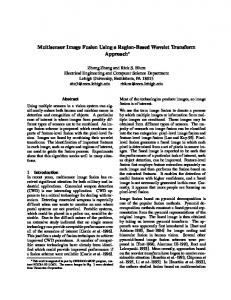
The angular velocity ω is a known constant turn rate within the sampling interval Δt , and for convenience we assume that w 2,k is a zero-mean Gaussian white noise with covariance Q2,w . B. System architecture From a structural point of view, a Cricket localization system can generally be divided into two approaches: active or passive architecture. The active mobile architecture has an active transmitter on the robot and periodically broadcasts messages over a wireless channel. Receivers deployed in known position then listen for the broadcast message and calculate the distance to the robot; the passive mobile architecture inverts the transmitter and receiver roles. Although the passive mobile architecture has advantages such as scalability, ability to maintain user location privacy, and ease of deployment, this research employs an active architecture in order to improve tracking performance [16]. As depicted in Fig. 2, the mobile node acts as an active transmitter to broadcast its distance information and beacon nodes then calculate distances from the active transmitter to the beacon. The raw data acquired are subsequently transferred to a base station prior to sensor grouping (SG), trilateration, and pseudo measurement generation being executed in the base station. Using multiple models from (1)
SYSTEM OVERVIEW
A. System components and robot dynamic model In this section, we look into the hardware components that form the basis of our system. The system consists of Cricket sensor nodes having Bluetooth communication capability, a moving robot, and a PC as the fusion center. As described in Section I, the Cricket nodes have RF and ultrasound transceivers and use the TDoA technique for distance calculations. Typically, passive Cricket nodes communicate with the base station through wired serial communication, but this is very impractical in a sensor network. Hence, we use Bluetooth communication for the passive node and attach an active node to the mobile robot to localize the robot as a mobile node. The mobile robot is a dual-drive robot equipped with an Atmel AVR 128 processor, IR sensors for obstacle avoidance, and photo couplers for line tracing. Fig. 1 illustrates both the active transmitter mounted on the mobile robot and passive sensor nodes. To model a maneuvering mobile robot in a 2-D Cartesian coordinate system the state includes the velocity, position, and turn rate as the trajectory moves along a curve. For the first model, a constant velocity model that describes the mobile robot movement is given by a nearly constant velocity: Mode1: x k +1 = F1x k + Gw1,k , ⎡1 Δt ⎢ 0 1 where F1 = ⎢ ⎢0 0 ⎢ ⎣⎢0 0
⎡ Δt 2 / 2 0 0⎤ 0 ⎤ ⎢ ⎥ ⎥ 0 0⎥ 0 ⎥ ⎢ Δt , G=⎢ ⎥. 1 Δt ⎥ 0 Δt 2 / 2 ⎥ ⎢ ⎥ 1 0 ⎦⎥ ⎢⎣ 0 Δt ⎥⎦
(1-b)
(1-a)
Fig. 1 Cricket active transmitter on the mobile robot
131
(1) ˆ (1) x L,k − d|k , PL,k − d
(12) PL,k −d
(2) ˆ (2) x L,k − d|k , PL,k − d
N) ( N) ˆ (L,k x − d|k , PL,k − d
Fig. 2. System structure block diagram.
and the obtained pseudo measurement equation, noise statistic estimates are calculated. Since the complex calculation (i.e., trilateration) of pseudo measurement, there could be small step sensing time delays. To deal with this situation IMM fixed-lag smoother is used with pre-defined information and the performance of these results is thereby enhanced by fusing the local IMM smoother estimates. III.
2(By,1 − B y,0 ) ⎤ ⎡ 2(Bx,1 − Bx,0 ) ⎢ ⎥ 2(B y,2 − B y,0 ) ⎥ r tr ⎡ Pxtr ⎤ ⎢ 2(Px,2 − Px,0 ) A=⎢ ⎥ , P = ⎢ tr ⎥ , L L ⎢⎣ Py ⎥⎦ ⎢ ⎥ ⎢ 2(Bx,m −1 − Bx,0 ) 2(By,m −1 − B y,0 ) ⎥ ⎣ ⎦ ⎡ ⎤ B2x,1 − B2x,0 + B2y,1 − B2y,0 − λ 2 (tˆ12 − ˆt 02 ) ⎢ ⎥ r ⎢ B2x,2 − B2x,0 + B2y,2 − B2y,0 − λ 2 (tˆ 22 − ˆt 02 ) ⎥ b=⎢ ⎥ , m ≥ 3. ⎢ ⎥ M ⎢ 2 2 2 2 2 ˆ2 2 ⎥ ˆ ⎢⎣ Bx,m −1 − Bx,0 + B y,m −1 − B y,0 − λ (t m −1 − t 0 ) ⎥⎦
LOCALIZATION ALGORITHM
A. Trilateration method Trilateration is a method used for determining the x, yand z-axis location of an object based on simultaneous range measurements from three stations located at known sites. This is a common operation not only in robot localization [17], but also in kinematics [18] and aeronautics [19]. For instance, if we let λ be the sound speed of a cricket node, di be the actual distance to each beacon Bi at known
If there are three beacons (i.e., m = 3), there are exactly two equations and two unknowns and A becomes a square matrix. If the determinant of A is non-zero, then (3) can be r solved to determine a unique value for P tr = [Pxtr , Pytr ]T ; for m >3 the method mentioned above (multilateration) is required. B. Sensor grouping and pseudo measurement As a moving target has practically unlimited mobility compared to nodes in the sensor network, it is reasonable to assume that the target can reach all nodes in the network with high probability. For this reason, all nodes must be able to measure the distance to the target. Since a single node can only measure the distance to the target, the nodes need to form groups of three to be able to perform trilateration. Then, one node from each group collects distance measurements from the other two and computes the position of the moving target. Hence, if there are L passive nodes we can make several groups through combinations L C3 for the trilateration calculation. In this case, however, one node can be frequently correlated with the other nodes and this correlation can lead to a degradation of the localization accuracy. For this reason, we restrict the formation of trilateration groups in a sensor network that one target has to at most four trilaterations; Fig. 3 illustrates sample trilateration groups as colored triangles.
coordinates ( Bx,i , By,i , Bz,i ) and ˆti be the measured time-offlight to beacons Bi , then the following distance equation holds: (Pxtr − Bx,i )2 + (Pytr − B y,i )2 + (Pztr − Bz,i ) 2 = d i 2 = (λˆt i ) 2 .
(2)
Note that if all beacons are installed in the same x-y plane, the z coordinate representing the beacon height can be eliminated in the distance equation, and the following linear equation is defined for the unknown target location r P tr = (Pxtr , Pytr )T : r r AP tr = b,
(3) r
(4)
r
where the matrix A and vectors P and b are given by
132
system from a series of incomplete and noisy measurements. The estimate of the current state is computed based on the estimated state from the previous time step and the current measurement, but in the case of a large maneuvering index [15] and inherent sensor delay, an IMM fixed lag smoother [13] is preferred over a standard Kalman filter. Fixed lag smoother obtains an estimate of the state at time (k-d) given measurements up to and including k, where the time index k continually changes as obtaining new measurement, but the lag N is a constant. Therefore, a fixed lag smoother can be used as online estimator of d times delayed measurement. Hence, here to enhance the localization accuracy a fixed lag IMM smoother is employed to estimate the smoothed state from pseudo measurements depicted by the dynamic equations (1) and (5) so that our system is dedicated to localization of maneuvering target and signal processing of inherent delays on pseudo measurement. The IMM smoother algorithm consists of four steps: initialization, interaction, combination and initialization for the augmented system [13].
Fig. 3. Sample trilateration groups in a sensor network.
Using the trilateration algorithm described in the previous sub-section and the sensor grouping, a pseudo measurement (N) T set Yk = [y (1) k ,L, y k ] of the position of the moving target can be written as (i) y (i) k = Hx k + v k ,
(5)
D. Multisensory data fusion algorithm We now have multiple measurements that observe the same target; the next problem is how to effectively combine these measurements (5). Several distributed sensor fusion architectures have been discussed in [21, 22] and algorithms for distributed estimation fusion have been developed in [23]. In this paper, we use the matrix weight fusion formula, which represents an optimal mean-square linear combination of the local estimates with a matrix weight [23]. According to (1) and (5), we have N dynamic subsystems (i=1,…,N) with state vector x k ∈ ℜ4 and
where y(i) k , i=1,…N, is the pseudo measurement with trilateration group index i, N is the number of groups, and x k = [Px Vx Py Vy ]T , Px = Pxtr , Py = Pytr . The measurement noise v (i) k is assumed to be additive white Gaussian noise with
covariance Q(i) v , defined by ⎫⎪ ⎡Q w v (kj)T ⎤ ⎬ = Q(ij)δ t − k , Q(ij) = ⎢ ⎦ ⎢⎣ SiT ⎭⎪
Sj ⎤ ⎥ ≥ 0. Q(ij) ⎥ v ⎦
(6)
2 measurement vector y(i) k ∈ ℜ . Using augmented system [13], denote the fixed lag smoother of the state x k − d , d > 0 based
(i) where Q(ii) v = Q v , E is the expectation, and δ t − k is the Kronecker delta function. In addition, the measurement noise is assumed to be independent of the state, i.e., Si , S j = 0, but because each distance measurement is used
ˆ (i) on the measurement y(i) k and mode L by x L,k − d|k . Then, to
find xˆ (i) L,k − d|k we can apply the IMM smoother [13] such that
more than one time during the trilateration calculations, the pseudo measurements y(i) k , i=1,…N, are highly correlated with each other; hence, the measurement noise covariance matrix Q(ij) v in the experimental setup is not a diagonal matrix. In practice, however, we often encounter a case in which the noise statistics parameters (6) are unknown. Thus, tuning of the noise intensity matrix is very important, especially for system implementation. In this paper, a distributed identification strategy based on the correlation function and weighting average approach [14], a well known method, is used to tune the linear system (1-a) and measurement (5) noise statistics. Fig. 4 shows results of self tuning algorithm.
100
5
80
4 3
60
Qw
Qv1
⎧⎪ ⎡ w k ⎤ E ⎨ ⎢ (i) ⎥ ⎡ w Tk ⎣ ⎩⎪ ⎣⎢ v k ⎦⎥
40
Qv2
0
0 0
100
200 300 Time k
400
−1
500
5
5
4
4
3
3
2 1
C. IMM smoother Kalman filters [20] have been shown to be effective recursive estimators for estimating the state of dynamic
2 1
20
Qv3
⎡1 0 0 0 ⎤ (i) y (i) ⎥ x k + vk , k =⎢ ⎣0 0 1 0⎦
0
100
200 300 Time k
400
500
0
100
200 300 Time k
400
500
2 1
0
0
−1
−1
0
100
200 300 Time k
400
500
Fig. 4 Estimates of system and measurement covariances
133
Pk(ij) − d|k =
∑ {P M
(ij) L,k − d|k
L =1
⎤ + ⎡ xˆ (i) − xˆ (i) k − d|k ⎦ ⎣ L,k − d|k
(10)
T j) ˆ ( j) ⎤ ⎫ × ⎡ xˆ (L,k − d|k − x k − d|k ⎦ ⎬ μ L,k , ⎣ ⎭
(ij) where PL,k − d|k is depicted in [24] without system mode L.
IV.
In this section we demonstrate the performance of the proposed algorithm in a real wireless sensor network. In this scenario, a number of nodes in a sensor network are used to estimate the position of a mobile robot. For this task, we used an unmanned robot equipped with a cricket node and four wireless sensor nodes. Fig. 4 presents the tuned system and measurement variances based on [15] and Fig. 5 illustrates the experimental setup. We implemented the steady state covariance values of Fig. 4 at k = 500 and assumed that multiple system models (1) have identical system noise variance; i.e., QL,w = Q w , L = 1, 2,..., M. The
Fig. 5 Experimental setup
xˆ (i) k − d|k = Pk(i)− d|k =
M
∑ xˆ L =1 M
(i) L,k − d|k μ L,k ,
∑ {P L =1
(i) L,k − d|k
⎤ + ⎡ xˆ (i) − xˆ (i) k − d|k ⎦ ⎣ L,k − d|k
EXPERIMENTAL VERIFICATION
(7)
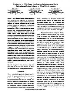
sampling time Δt = 0.4 and a fixed lag d=2. To show the localization performance we used a line-tracer robot and track (Fig. 5) that can exactly know real trajectory of robot. Nevertheless though, there could be arise slipped situation we assume that the target robot completely follows track to compare performance of proposed method. The figure illustrates the experimental results for a 120 cm x 180 cm track. The bold line is the track schematic, based on the assumption that the mobile robot will exactly follow the line, and the ‘triangle’ line and ‘*’ markers represent the 3 SG measurements and fused smoothers, respectively. The experimental results show that the localization performance of the proposed method outperforms a traditional trilateration method (i.e., the SG measurements). We could also confirm that the proposed method filters noisy measurements well, especially for huge measurement fluctuations, resulting from the effect of multiple data fusion.
T ⎤ ⎫ × ⎡ xˆ (i) − xˆ (i) k − d|k ⎦ ⎬ μ L,k , ⎣ L,k − d|k ⎭
where L = 1, 2,..., M is the index of system modes and μ L,k is (i) the mixing probability of mode L at time k. In (7), PL,k − d|k
is the error covariance of mode L with fixed lag d, i.e., (i) % (i) % (i) ˆ (i) PL,k − d|k = cov{x L,k − d|k − d }, where x L,k − d|k = x L,k − d − x L,k − d|k and Pk(i)− d|k is mode combined error covariance. Thus, from (7) ˆ (N) we have N local fixed lag smoothers, xˆ (1) k − d|k ,..., x k − d|k , based (N) on the measurements y(1) k ,..., y k , and their corresponding
error covariances Pk(1)− d|k ,..., Pk(N) − d|k . Then, the fusion fixed lag smoother xˆ fus k − d|k of the state vector based on the overall measurements (5) can be constructed from the local IMM smoothers using the matrix weight fusion formula [23]:
180 SG Measurement1 SG Measurement2 SG Measurement3 Fusion IMM smoother Real track
160
xˆ fus k − d|k =
N
∑c
N
∑c
(i) ˆ (i) k x k − d|k ,
i =1
(i) k
= In ,
140
(8)
i =1
120
N
∑ ( i =1
)
(ij) (iN) c(i) k Pk − d|k − Pk − d|k = 0,
N
∑
y−axis [cm]
(N) where the time-varying weighting matrices c(1) are k ,...,c k determined by
100
80
60
c(i) k = I n , j = 1,...N − 1,
(9)
40
i =1
20
(i) where Pk(ii) − d|k ≡ Pk − d|k is the covariance determined by (7) and
0
Pk(ij) − d|k , i ≠ j is the cross-covariance defined by
0
20
40
60 x−axis [cm]
80
Fig. 6 Experimental results
134
100
120
Furthermore, original multilateration methods cannot cover all regions of interest in a large-scale network, as opposed to the proposed weighted fusion method; this method can cover large-scale networks because it can dynamically change SG, and then according to the results of SG it can continue to estimate the target location. V.
[12] N. B. Priyantha, “The cricket indoor location system,” Ph.D. Thesis, Massachusetts Institute of Technology, June 2005. [13] B. Chen, J. K. Tugnait, “Interacting multiple model fixed-lag smoothing algorithm for markovian switching systems,” IEEE Trans. Aerosp. Electron. Syst, vol. 36, no. 1, Jan. 2000. [14] S. Sun, “Optimal and self-tuning information fusion Kalman multistrp predictor,” IEEE Trans. Aerosp. Electron. Syst, vol. 43, no. 2, Apr. 2007. [15] Y. Bar-Shalom, X.R. Li and T. Kirubarajan, Estimation with Applications to Tracking and Navigation, John Wiley & Sons, New York, 2001. [16] A. Smith, H. Balakrishnan, M. Goraczko, N. B. Priyantha, “Tracking moving devices with the Cricket location system,” 2nd Int. Conf. Mobile Systems, Applications and Services, Boston, MA, June 2004. [17] L. E. Navarro-Serment, C. J. J. Paredis, and P. Khosla, “A beacon system for the localization of distributed robotic teams,” in Proc. Int. Conf. Field and Service Robots, Pittsburgh, PA, Aug. 1999, pp. 232237. [18] F. Thomas, E. Ottaviano, L. Ros, and M. Ceccarelli, “Coordinate-free formulation of a 3-2-1 wire-base tracking system using Cayley-Menger determinants,” in Proc. IEEE Int. Conf. Robotics and Automation, vol. 1, Taipei, Taiwan, 2003, pp. 255-363. [19] D. E. Manolakis, “Efficient solution and performance analysis of 3-D position estimation by trilateration,” IEEE Trans. Aerosp. Electron. Syst., vol. 32, pp. 1239-1248, Apr. 1996. [20] F. L. Lewis, Optimal Estimation with an Introduction to Stochastic Control Theory, John Wiley & Sons, New York, 1986. [21] Y. Bar-Shalom (Ed), Multitarget-Multisensor Tracking: Advanced Applications, Artech House, Norwood, MA; 1990. [22] X. R. Li, Y. M. Zhu, J.Wang and C.Z.Han, “Optimal linear estimation fusion - Part I: Unified fusion rules,” IEEE Trans. Inf. Theory, vol. 49, no. 9, pp. 2192-2208, 2003. [23] V. Shin, Y. Lee, and T.-S. Choi, “Generalized Millman's formula and its applications for estimation problems,” Signal Processing, vol. 86, no. 2, pp. 257-266, 2006. [24] S. Sun, “Distributed optimal component fusion wighted by scalars for fixed-lag Kalman smoother,” Automatica, vol. 41, no. 12, Dec. 2005.
CONCLUSIONS
In this paper, we proposed a solution for enhancing the performance of localization in wireless sensor networks. To localize a target in a Cricket sensor network, multiple pseudo measurements from trilateration and an IMM fixed lag smoother were combined. For the IMM fixed lag smoother, a nearly constant velocity and coordinate turn model were implemented to track the target location. The multiple pseudo measurements generated from sensor grouping and trilateration method were then employed to calculate the fusion fixed lag smoother, which thereby enhanced the localization performance. Multiple data fusion was then completed via a weighted matrix algorithm [23] and the experimental results of the proposed method show that it performed well in a wireless sensor network environment, and that it could possibly extend a large-scale Cricket sensor network. ACKNOWLEDGMENT This work was supported by Basic Science Research Program through the National Research Foundation of Korea (NRF) funded by the Ministry of Education, Science and Technology (No. 2009-0077396 and No.2010-0009925). REFERENCES [1] M. M. Kuritsky, et al., “Inertial navigation,” Proceedings of the IEEE, vol. 71, no. 10, pp. 1156-1176, Oct. 1983. [2] S. Panzieri, F. Pascucci and G. Ulivi, “An outdoor navigation system using GPS and inertial platform,” in Proc. IEEE/ASME Inter. Conf. Advanced Intelligent Mechatronics, Como, Italy, Jul. 2001. [3] R. Mautz, “The challenges of indoor environments and specification on some alternative positioning systems,” in Proc. the 6th workshop on positioning, navigation and communication 2009. [4] M. Popa, J. Ansari, J. Riihijarvi, and P Mahonen, "Combining cricket system and inertial navigation for indoor human tracking," IEEE Conf. Wireless communications & networking, Mar. 2008. [5] P. Bahl and V padmanabhan, "RADAR: An in-buildding RF-based user location and tracking system," INFOCOM 2000. [6] J. Hightower, C. Vakili, G. Borriello, and R. Want, “Design and calibration of the spoton ad-hoc location sensing system,” 2001. [7] P. M. Djuric, M. Vemula, M. F. Bugallo, “Signal processing by particle filtering for binary sensor networks,” IEEE Digital signal processing workshop & Signal processing education work shop 2004. [8] J. Yim, C. Park, J. Joo, S. Jeong, “Extended Kalman filter for wireless LAN based indoor positioning,” Decision support systems, vol. 45, no. 4, pp. 960-971, November 2008. [9] X. Wang, D. Musicki, Target tracking using energy based detections, 10th Inter. Conf. Information fusion, Jul. 2007. [10] A. Ward, A. Jones, and A. Hopper, “A new location technique for the active office,” Personal Communications, IEEE [see also IEEE Wireless Communications], vol. 4, no. 5, pp. 42-47, 1997. [11] R. Want, A. Hopper, V. Falcao, and J. Gibbons, “The active badge location system,” ACM Trans. on Information Systems, vol. 10, no. 1, pp. 91-102, 1992.
135